It has been a while since the last post, so I thought it would be a good idea to provide an update in the progress of the project.
The application for flight is still with CASA/AirServices.
Some good progress has been made in regards to Spot/Gimbal mechanism. A gimbal contraption has been constructed almost completely out of PVC pipe to allow the Spot Messenger to be orientated correctly (upwards), regardless of the orientation of the payload.
Since the project has changed quite a bit, I’ve decided to do up a short video of the payload systems. Please find below.
It was decided after a bit of risk analysis regarding the parachute that it would be advisable to have a gimbal arrangement to ensure that the SPOT Messenger antenna is pointing directly up at all times. This is because Spot Messengers need to be orientated correctly; and if for whatever reason the parachute did not deploy and the HAB did not maintain this orientation for sufficient time, then we may not get any measurements on its decent. [That being said, I did perform a few tests with the Spot Messenger around the wrong way and it did seem to function OK. But we cannot take chances.]
There are several designs that can be found on various sites using hamster wheels and various ways to “attach” a spot messenger. I decided to design one from scratch.
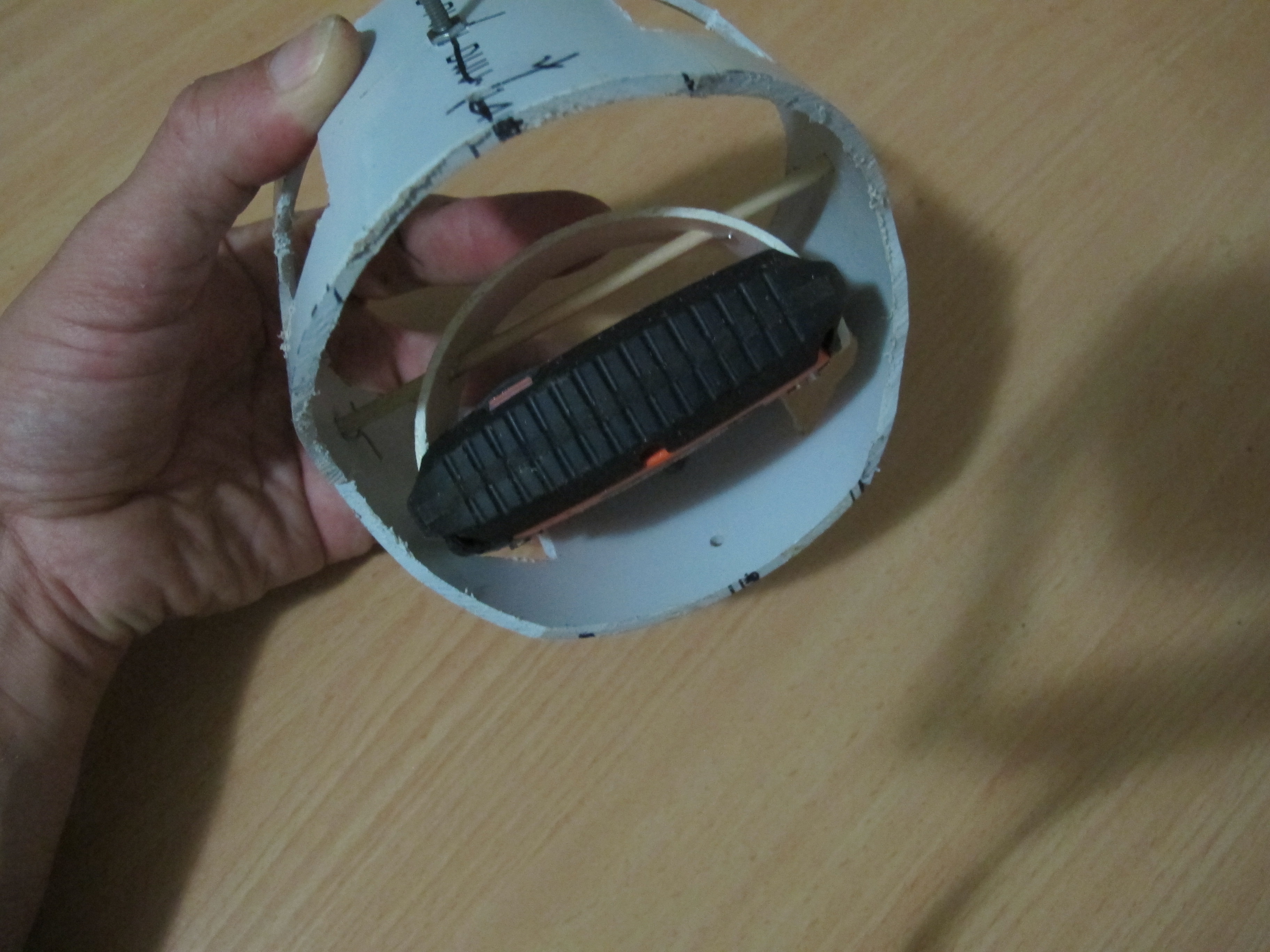
Firstly, I got some 90mm PVC pipe and cut out a 1/3 circle segment about 20mm wide. I was able to fit this snug into the Spot Messenger III slits at each end. The 90mm PVC pipe was just the perfect thickness and the “spring” in the PVC pipe helps to keep the pipe segment “attached” to the Spot Messenger. Then a hole was drilled through this pipe segment and a skewer was passed through. This was all mounted inside a 110mm sewer PVC pipe. This 110mm sewer pipe is cut in various places to allow the easy rotation of the Spot Messenger and to reduce weight. Pieces of wire are inserted in VERY small holes drilled through the skewer to stop
The 110mm sewer pipe segment happens to sit very neatly into a tissue box which we will use to build a fiber-glass device to allow rotation of the whole system inside the payload.
I’ve taken a few pictures of the device and attached them below.
Inside view showing how Spot Messenger is attached
You can see how the PVC gimbal should easily move inside the tissue box.
The HAB payload needs a small/suitable antenna. I decided that it would be easier and a lot more fun to make the antenna; rather than buy one. It would also reduce costs and a lot of additional knowledge and know-how would result.
Materials
Material for this are:-
Material
Quantity
Notes
RG-227U Cable
30cm
2mm solid copper wire
1 metre
I choose thick wire to increase rigidity and to increase bandwidth
Solder
As much is required
Plywood 200mm x 200mm
1
Used to create a “jig”, to which the antenna was created.
Various wood pieces
40mm x 40mm x 15mm
3
Used to create a “jig”, to which the antenna was created.
The cut-down mechanism did not work as well as hoped during the trial launch. This post discusses the issues and proposes a possible solution.
The problem with the cut-down mechanism
The main problem with the cut-own mechanism is that it doesn’t have sufficient power to burn a hole through balloon latex at and near the throat; at least not in a reasonable amount of time. One needs to remember that latex, being a polymer has a lot of strong chemical bonds between atoms. A lot of energy is needed to disrupt them. Also once a hole is made, there is negligible force present at the throat to open the slit to let out a decent amount of Helium gas.
Some testing was done with “best case scenario” where we had a good 6.75volt power supply with minimal hook-up wire connected to cut-down device against thick latex, thicker than what would need to be burnt in reality, but not excessively thick. The Nichrome wire hardly made a dent against the Latex. Even after repeated attempts, we had very little to show.
The conclusion I draw from this is that we cannot rely upon the cut-down mechanism as it stands now. Even if the latex is stretched a little, we cannot expect it to burst the balloon, or even put a hole in it. A different strategy or alternative cut-down design is required.
A new approach
We need to try and melt the balloon envelope where it is thinner and where the strain is greater. Remember that once it is melted, the strain/stresses in the balloon latex envelope are what help to make the hole greater. In the absence of any strain/stresses (near and at the throat of the balloon), there is little chance in the growth of the hole.
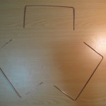
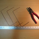
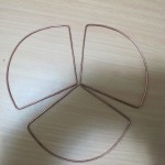
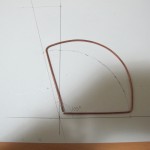
Below is a picture of a proposed system (still yet to be completed). Its segment arm is “spring” loaded so that it should rest against the interior of the balloon surface. At the pointy end is some nichrome wire to burst the balloon.
Alternate cut-down mechanism
We will be inflating another balloon with air this time and simulating a cut-down.