Gimble for the Spot Messenger

It was decided after a bit of risk analysis regarding the parachute that it would be advisable to have a gimbal arrangement to ensure that the SPOT Messenger antenna is pointing directly up at all times. This is because Spot Messengers need to be orientated correctly; and if for whatever reason the parachute did not deploy and the HAB did not maintain this orientation for sufficient time, then we may not get any measurements on its decent. [That being said, I did perform a few tests with the Spot Messenger around the wrong way and it did seem to function OK. But we cannot take chances.]

There are several designs that can be found on various sites using hamster wheels and various ways to “attach” a spot messenger. I decided to design one from scratch.

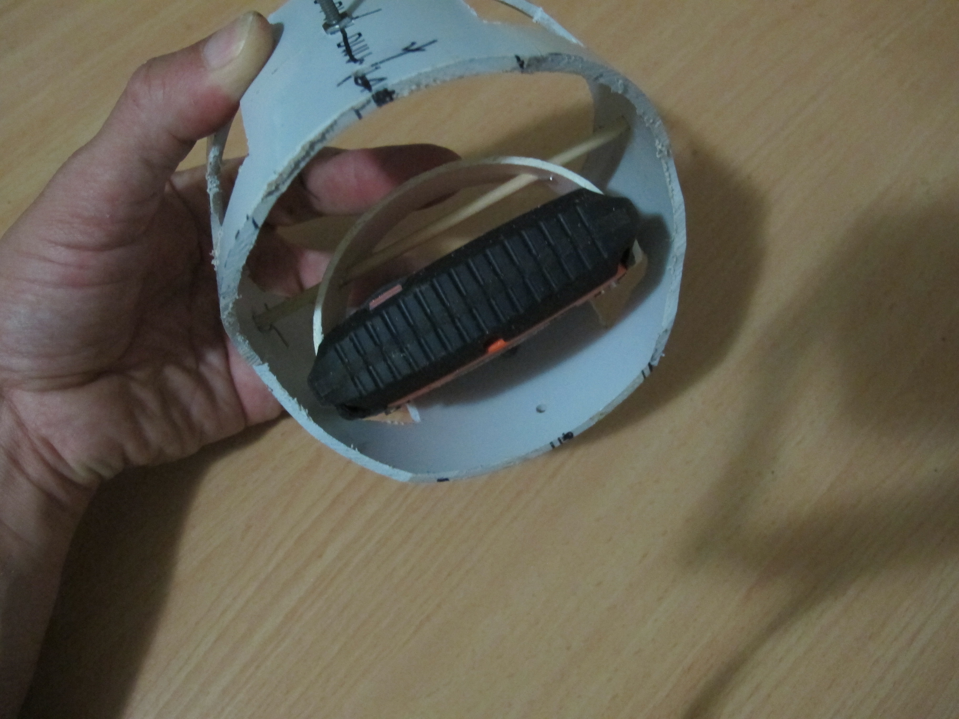
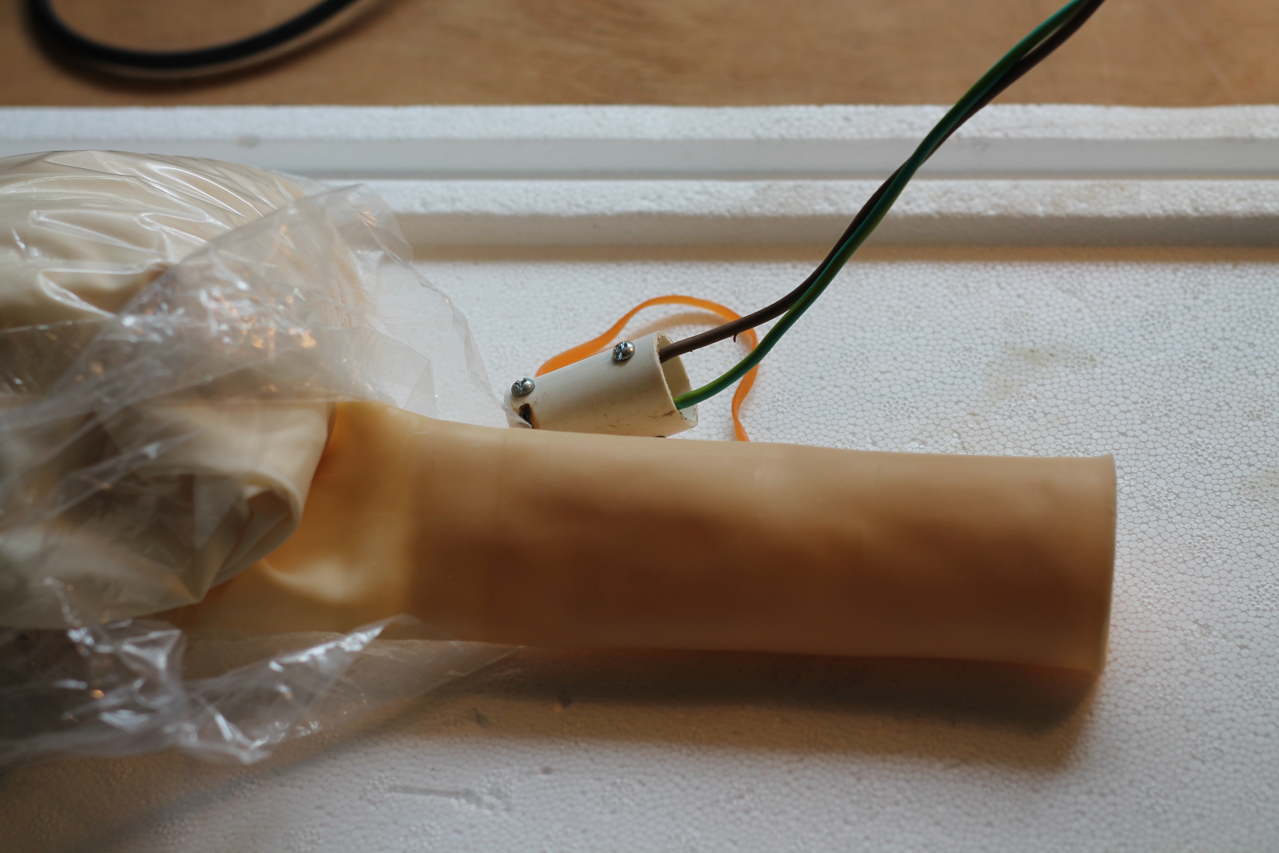
Firstly, I got some 90mm PVC pipe and cut out a 1/3 circle segment about 20mm wide. I was able to fit this snug into the Spot Messenger  III slits at each end. The 90mm PVC pipe was just the perfect thickness and the “spring” in the PVC pipe helps to keep the pipe segment “attached” to the Spot Messenger. Then a hole was drilled through this pipe segment and a skewer was passed through. This was all mounted inside a 110mm sewer PVC pipe. This 110mm sewer pipe is cut in various places to allow the easy rotation of the Spot Messenger and to reduce weight. Pieces of wire are inserted in VERY small holes drilled through the skewer to stop

The 110mm sewer pipe segment happens to sit very neatly into a tissue box which we will use to build a fiber-glass device to allow rotation of the whole system inside the payload.

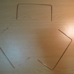
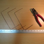
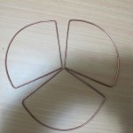
I’ve taken a few pictures of the device and attached them below.


Inside view showing how Spot Messenger is attached


You can see how the PVC gimbal should easily move inside the tissue box.

Making the CloverLeaf Antenna

The HAB payload needs a small/suitable antenna. I decided that it would be easier and a lot more fun to make the antenna; rather than buy one. It would also reduce costs and a lot of additional knowledge and know-how would result.

Materials

Material for this are:-

Material Quantity Notes
RG-227U Cable 30cm
2mm solid copper wire 1 metre I choose thick wire to increase rigidity and to increase bandwidth
Solder As much is required
Plywood 200mm x 200mm 1  Used to create a “jig”, to which the antenna was created.
Various wood pieces
40mm x 40mm x 15mm
3  Used to create a “jig”, to which the antenna was created.

Design and Construction

Design is based a lot off what is described at:-

The Cloverleaf FPV Antenna

In fact, I followed it word for word, picture for picture…except that I created a Right Hand Polarized version.

Improving the Cut-down mechanism

The cut-down mechanism did not work as well as hoped during the trial launch. This post discusses the issues and proposes a possible solution.

The problem with the cut-down mechanism

The main problem with the cut-own mechanism is that it doesn’t have sufficient power to burn a hole through balloon latex at and near the throat; at least not in a reasonable amount of time. One needs to remember that latex, being a polymer has a lot of strong chemical bonds between atoms. A lot of energy is needed to disrupt them. Also once a hole is made, there is negligible force present at the throat to open the slit to let out a decent amount of Helium gas.

Some testing was done with “best case scenario” where we had a good 6.75volt power supply with minimal hook-up wire connected to cut-down device against thick latex, thicker than what would need to be burnt in reality, but not excessively thick. The Nichrome wire hardly made a dent against the Latex. Even after repeated attempts, we had very little to show.

The conclusion I draw from this is that we cannot rely upon the cut-down mechanism as it stands now. Even if the latex is stretched a little, we cannot expect it to burst the balloon, or even put a hole in it. A different strategy or alternative cut-down design is required.

A new approach

We need to try and melt the balloon envelope where it is thinner and where the strain is greater. Remember that once it is melted, the strain/stresses in the balloon latex envelope are what help to make the hole greater. In the absence of any strain/stresses (near and at the throat of the balloon), there is little chance in the growth of the hole.

Below is a picture of a proposed system (still yet to be completed). Its segment arm is “spring” loaded so that it should rest against the interior of the balloon surface. At the pointy end is some nichrome wire to burst the balloon.


Alternate cutdown mechanism
Alternate cut-down mechanism


We will be inflating another balloon with air this time and simulating a cut-down.


HackHD Camera Temperature

The HackHD camera is a cost-effective light camera chosen for the mission. It does have one  drawback; it gets extremely hot during operation. This post identifies the issues this poses and puts forward a possible solutions to _try_ and mitigate these issues.

The Problem

As the payload ascends, it will experience extreme temperatures and pressures. During the initial ascent, there will be a drop in temperature and the pressure will drop slowly. There will be a chance that the camera can cool from radiation and a little bit of convection. As the payload continues to ascend into the Stratosphere, the air pressure drops off to almost zero. Convection isn’t going to work. Radiation of the heat is the only mechanism by which it can cool. There is absolutely no point having a ‘fan’ installed to cool it down because there won’t be anything to ‘blow’ on to the hot chips.

The Solution

We need to ensure that the HackHD can radiate heat as effectively as possible. Remember that we just want to make the HackHD last as possible. It may be close to impossible to allow it to operate the whole time. Ways to address this are:-

1. Keep the journey as short as possible up in the Stratosphere

2. Take video for a few minutes, then turn off to allow it to cool down, then turn it back on again. Or alternatively, take photos instead of video

3. Add heat-sink to transfer heat away, to increase area of surface radiating heat. The flow of heat is directly proportional to the surface area of the object.

The heat Sink

Below are some pictures of the device that ‘hugs’ the HackHD camera.


Look inside between bottom bottom veraboard and HackHD


Bottom view
Bottom view
Top View
Top View

We have 2mm screws that connect the veroboard to the HackHD using the three holes it has. We have bent copper plate soldered to the veroboard making physical contact with the three chips. We use heat conducting paste to improve heat flow. We then have another piece of veroboard (no copper on any side) attached to the other veroboad using 3mm screw/nuts. We have two spaces to give an appropriate gap. This last bit of veroboard helps to keep hands away from the underside of the HackHD, reducing chance of damage (static), etc.


Initial Spot Messenger Testing

A Spot Messenger account has been purchased and some initial testing has been done to see how the Spot Messenger fairs with the other electronics. Other Balloon launches have been plagued with interference issues between the SPOT messengers and the other Electronics. Initial testing suggests that the Spot Messenger works fine with other electronic components.

The “Extreme” plan has been purchased which allows Messages every 2.5 minutes. This means that when the balloon is descending, at a fairly quick pace, the chance of getting a message through is going to be reasonably large. One calculation had a time of 13minutes to descend from 6500metres to approximately 0, which means up to 5 ‘way-points’.

We will need to do more testing on how forgiving(or unforgiving) the SPOT Messenger is when orientated in a non-horizontal orientation.


Request for launch sent to CASA

After much thought and investigations, we have filed an application with CASA for permission to a flight about 100km SW of Mareeba. The launch is to be done as a “Light” Balloon and is for a flight on 1st of November 2014.

Below is map showing one such predicted flight. Of course, the actual flight plan varies quite substantially from day to day.

One of many possible flight paths

Unfortunately the application is not going to be straight-forward because while the balloon does meet requirements of a Light Balloon with it’s payload weight, it does not meet the requirement of the balloon diameter (<2m through-out the whole flight).

As you will notice, we have lodged the application with CASA very early on, so as to allow a long processing time, or possibly the lodgement of a second application, should it be required. Hopefully it will not come to this; but do not want to leave anything to chance.


UPDATE: 6th July 2014

That application is in the process of being looked into. Still waiting for some concrete response in regards to what other conditions, exemptions, etc may be required.

The Organising of the Balloon launch (Progress as of June)

The process of organising the launch and finishing of the Balloon payload is taking a long time to do. Many of my work an family commitments mean that I’m only to progress things slowly. The following are the main areas of concern

1. Obtaining a vehicle to transport self and equipment and others to site

2. Confirming whether SPOT3 or SPOT2 is the best Messenger to add to the payload

3. Investigating procedure to fill the balloon

4. Investigating what the best way is to ‘test’ the fill procedure, with least expense, but most realistic setting

5. Touching up on the document for CASA, requesting approval

6. Obtaining a radar reflector

7. Obtaining a spare Totex 800Gram balloon

8. Determining the best way to include Family (esp Jeremy), if the decide they’d like to be at the launch.

As one can see, there is still very much that needs to be done. I am getting a little more confident with these points.

1. Still need to test drive a Toyota Hilux, but thinking that a Ford Ranger will be the one to go for

2. The SPOT3 Messenger in ‘Tracking Mode’ apparently won’t turn off for 24hrs

3. I’ve found a UK site that describes a PVC like http://wiki.ukhas.org.uk/guides:fill_tube

4. I am thinking I will purchase an Air Cylinder from BOX (~$60) and use that as if it were Helium. I’ll need to make sure the same connetions, pressure, regulator are used for it as the He cylinder.

5. I’ve confirmed as long as I’m out side the range of the Cairns Secondary Radar (474km), I do not need a transponder. This means I need to be a LONG way west. Normanton is 505km West

6. The CASA regulations state that for a Medium Balloon, a radar reflector is required. I’ve located one http://www.sky-probe.com/Accessories-Radar_Reflector.html#!prettyPhoto

7. I might have to purchase one through UK again. A bit wasteful to have to buy it through a second purchase…a bit of an oversight

8. Looking at possibly flying family to Normanton and they can hire a car. Will see.


Obtaining a Spot Messenger

As usual, it pays to do ones due diligence before purchasing components; and the Spot Messenger is no exception.

The Spot Messenger will provide a means of locating the HAB while it is below 6500 metres. This will allow us to locate the payload…which would be close to impossible with the GPS because LOS issues might stop us from getting radio reception when it is closing in on the surface of Earth. There is however a potential problem with the GEN3 version of Spot Messenger. It has a feature to power down the Spot Messenger if there has been no activity for 1hr. With a flight duration of 2 hours, it is possible that the Spot Messenger might turn off before it is retrieved! Certainly not ideal. So I am considering purchasing the previous version of the Spot Messenger.

Radio Test 6

Did an extremely successful radio test on the 4th of May from Port Douglas to Buchans Point. The distance between these two locations is 35km. With the help of my wonderful neighbour we were able to :-

  • Confirm that the radio link at 1Watt over 35 km works extremely well, even with HAB in the least optimal orientation
  • Was able to transmit an image perfectly over the 35km link without any problems at the x-modem layer.
  • Was able to get the distance between the two locations (using my mobile GPS co-ordinates and the GPS co-ordinates of the HAB)
  • The cut-down mechanism was initiated and burnt through the rubberband a little
  • Confirmed that the Groundstation new battery configuration is working well.

The great thing about this test is that the Fresnel zone was 65% which means in the real launch, we would expect even better radio transmission results. There is no shadow of doubt that the link distance (as per rfd900 specs) of 40km is reliable and that the max link distance of 50km is probably easily achievable.

I see no reason to continue on with other aspects of the project.

Balloons at Parachute Arrived!

My Parachutes and Balloons have arrived!

I have purchased:-

  • 1 x 800G balloon
  • 2 x 350G Ballons

I got these all from the UK.

Below a peek at one of them. I haven’t taken it out because I don’t want to damage the balloon.

Throat of Totex 350Gram balloon next to cutdown mechanism