There was much thought and time spent trying to find a suitable design/construction procedure for a radar reflector. There are several ones on the Internet, e.g. Instructables one, but they did not seem that practical/suitable. This post describes how our Radar Reflector was built.
The requirements of a reflector are:-
It is light weight
It is able to perform its function regardless of the orientation
It is strong (rigid)
It is easy to construct and not overly expensive.
For materials I decided to use core-flute material (Sold at companies that create signs) and Aluminium tape (50mm x 5metre) from Jaycar and two cable ties.
The construction is best illustrated I think using some photos. Please see below:-
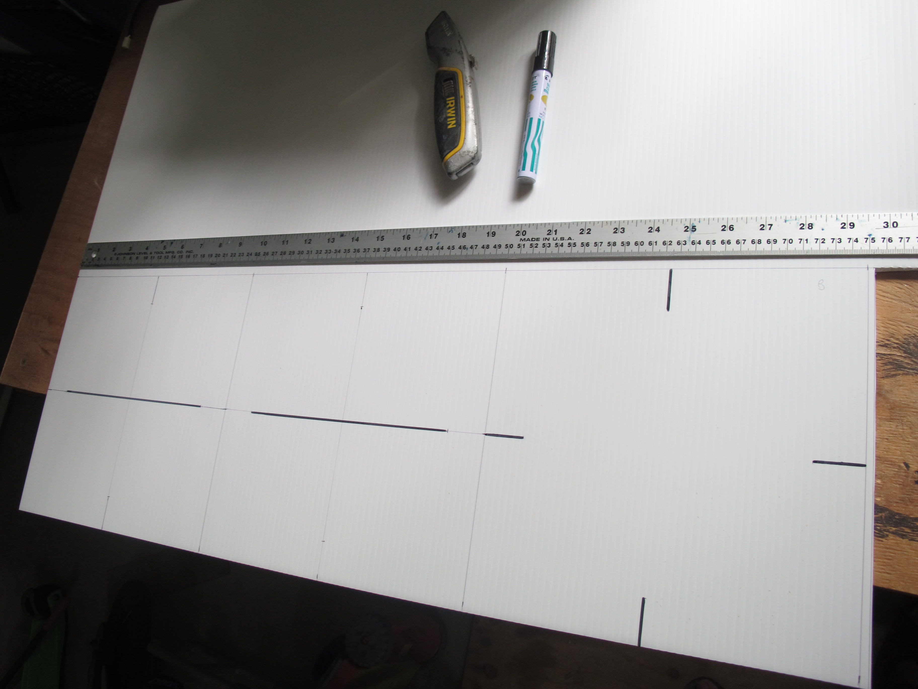
Measuring up – 3 squares – each with side of 250mm
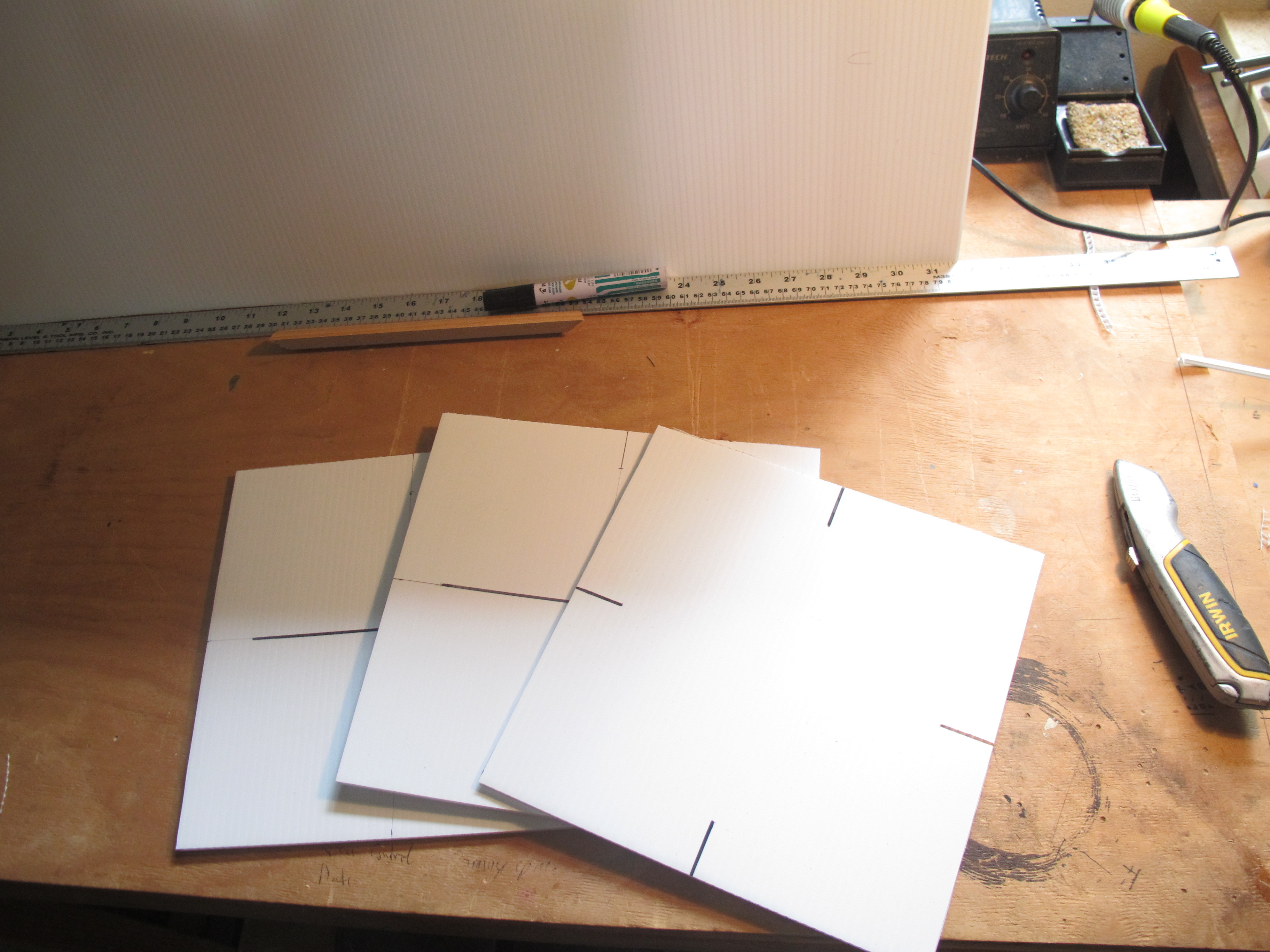
Cut out the squares using a blade. Dark lines indicate where we need to create incisions later on
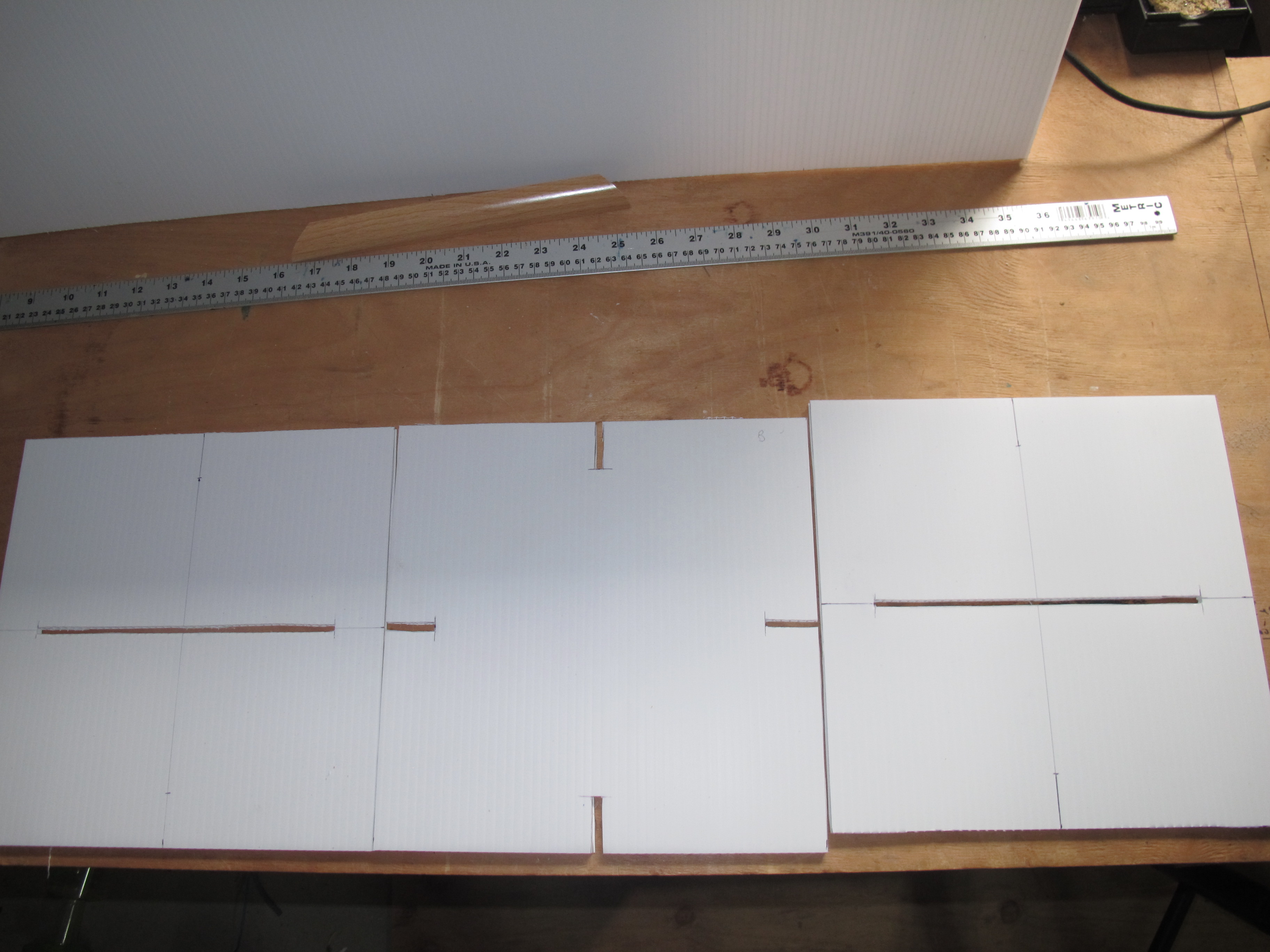
Incisions are made. Incisions are just a little narrower than the width of the Coreflute
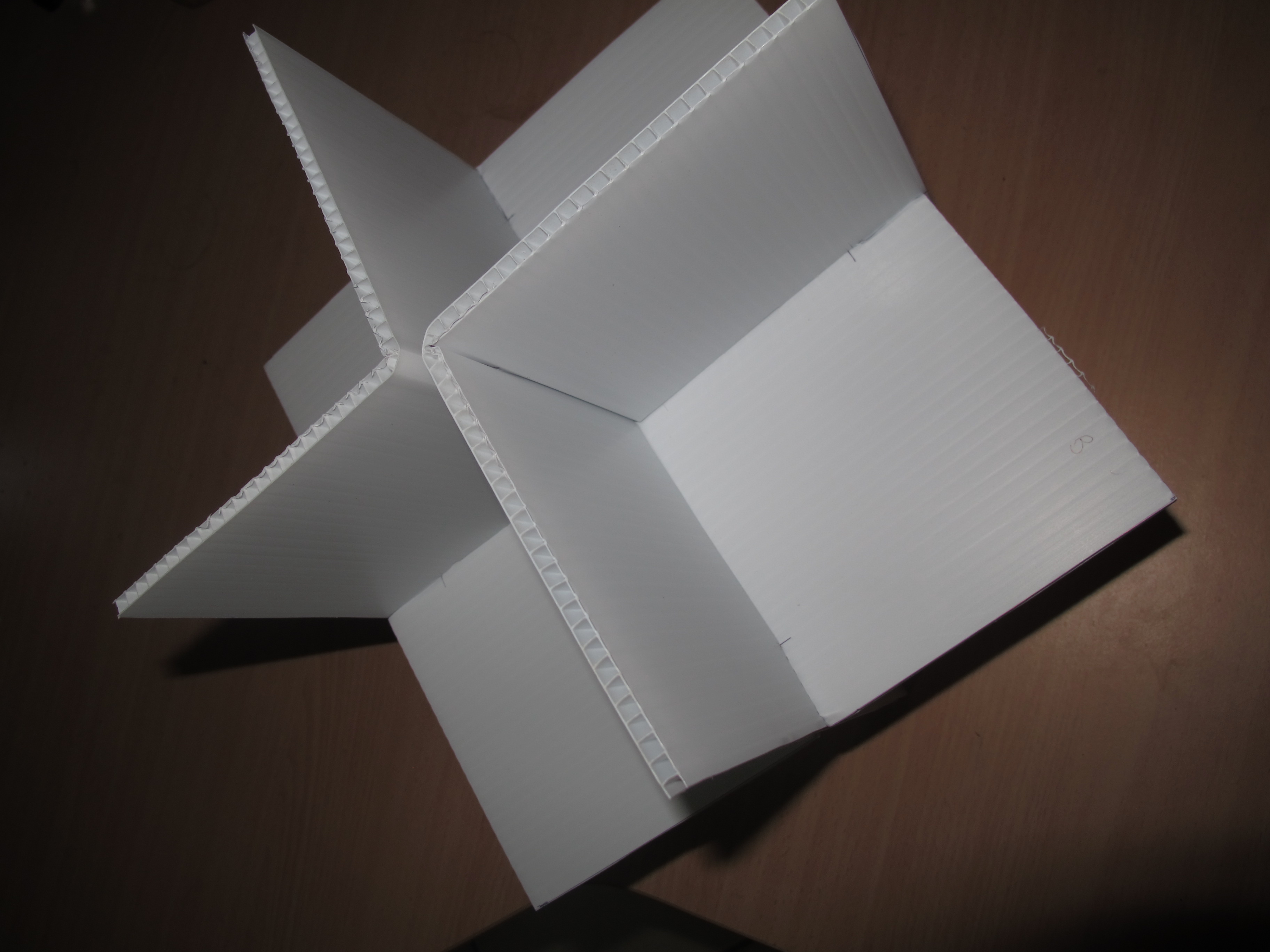
Assemble the three squares. Cables ties later connect two ‘right-angle’ pieces together.Apply Aluminium tape to all faces. Weight is 250grams
We will drill a hole later on in a corner for the thread. Will re-enforce this hole with additional Aluminium tape.
It became obvious that there are probably some ways to make the build process a lot easier. Possibly putting tape on initially before cutting and putting together.
I do also wonder if we “really” need to have Aluminium tape on both sides of the Coreflute; but decided in the end to apply it to both anyhow.
But it is strong/rigid, light, not too difficult to make and inexpensive.
It was decided after a bit of risk analysis regarding the parachute that it would be advisable to have a gimbal arrangement to ensure that the SPOT Messenger antenna is pointing directly up at all times. This is because Spot Messengers need to be orientated correctly; and if for whatever reason the parachute did not deploy and the HAB did not maintain this orientation for sufficient time, then we may not get any measurements on its decent. [That being said, I did perform a few tests with the Spot Messenger around the wrong way and it did seem to function OK. But we cannot take chances.]
There are several designs that can be found on various sites using hamster wheels and various ways to “attach” a spot messenger. I decided to design one from scratch.
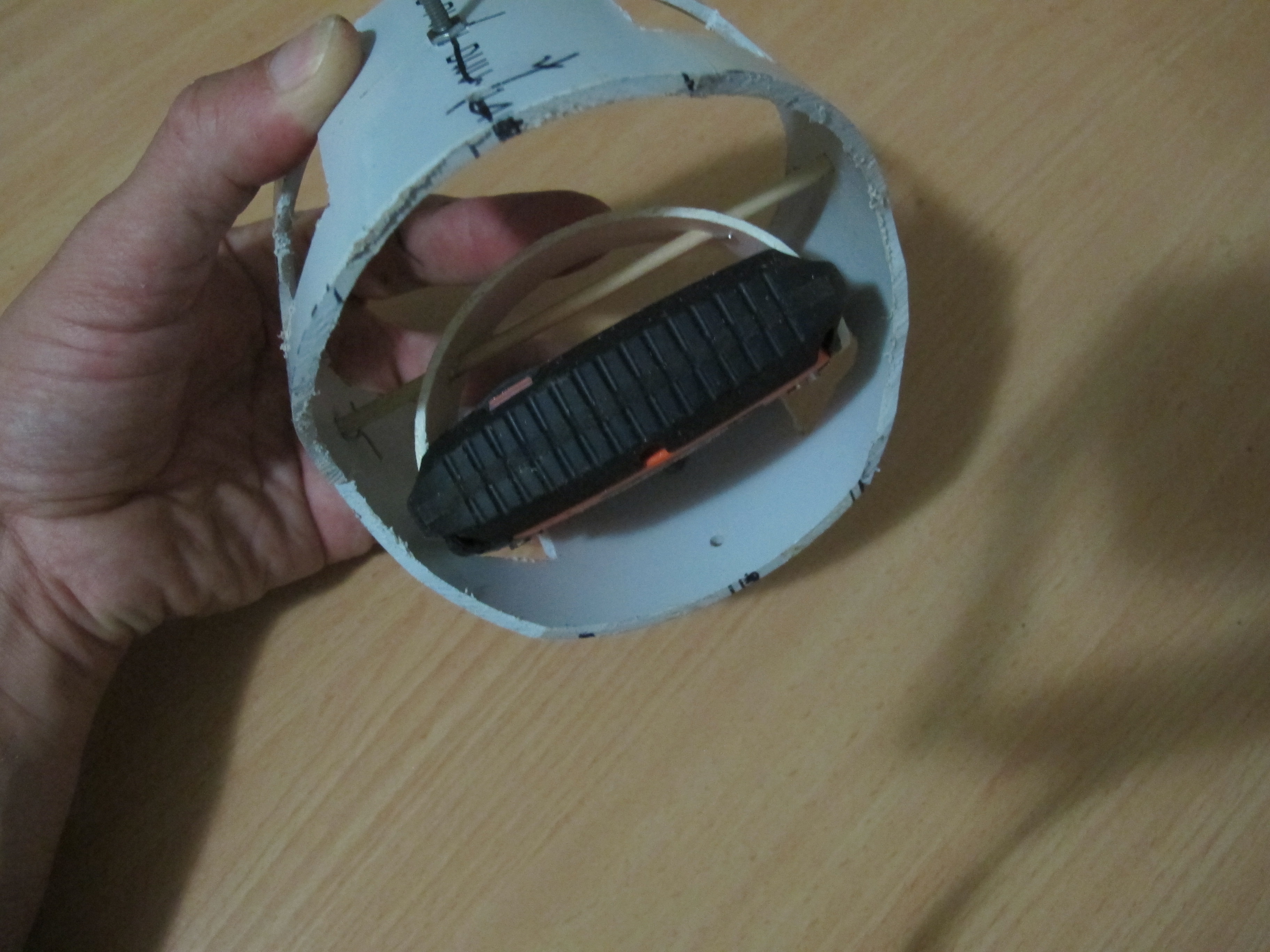
Firstly, I got some 90mm PVC pipe and cut out a 1/3 circle segment about 20mm wide. I was able to fit this snug into the Spot Messenger III slits at each end. The 90mm PVC pipe was just the perfect thickness and the “spring” in the PVC pipe helps to keep the pipe segment “attached” to the Spot Messenger. Then a hole was drilled through this pipe segment and a skewer was passed through. This was all mounted inside a 110mm sewer PVC pipe. This 110mm sewer pipe is cut in various places to allow the easy rotation of the Spot Messenger and to reduce weight. Pieces of wire are inserted in VERY small holes drilled through the skewer to stop
The 110mm sewer pipe segment happens to sit very neatly into a tissue box which we will use to build a fiber-glass device to allow rotation of the whole system inside the payload.
I’ve taken a few pictures of the device and attached them below.
Inside view showing how Spot Messenger is attached
You can see how the PVC gimbal should easily move inside the tissue box.
As usual, I underestimated the importance of the antenna and the difficulties involved in selecting what ultimately needs to be a compromise. We can’t have everything! We need to decide upon the antenna for the HAB and the ground antenna.
HAB Air Antenna
What we need out of an antenna
The things to consider are:-
Profile – horizontal and vertical – we want to to 360 degress around and require vertical radio to be maximum directly below and still be fairly strong up to 45 degrees and not so strong at the horizontal.
Impedance – It needs to match that of the XBee modules which is 50Ohms.
The gain – well, this is something we can’t control, because we need sufficient coverage (Profile above). It would be great if we can have a ground plane above the antenna to reduce radiation above the antenna.
Bandwidth requirements dictated by XBee is 902MHz to 928MHz
Other considerations
The cable and connectors are also very important because we lose a fair amount of the signal in these components, before it is even radiated.
Connectors need to be 50Ohm
Connectors needs to be easy to connect to cable
Connectors need to have suitable bandwidth
Cable needs to as low loss as possible (minimal attenuation)
Cable needs to be able to bend sufficiently to attach to antenna and XBee.
Cable needs to be 50Ohm to match the xBee modules.
Where to obtain
The antenna here might do the job. Still investigating this.
Ground Base Antenna
It is possible we might be best getting two types of antennas for the ground base station. A:-
Yagi
A spiral antenna
We consider what we need in these two antennas separately. I have read that during the initial stages of the flight, when the ground station is under the balloon, the radiation pattern is more circularly polarized. Use of a Yagi in this stage of flight would lead to highs and lows (absence) of signal, whereas a Spiral will be 3db down, but will not lose signal altogether.
As the HAB moves further away, the radiation coming from the HAB is closer to horizontally polarized, and so we can then employ the YAGI.
Yagi
What we need out of an antenna
The things to consider are:-
Profile – Highly directional
Impedance to be 50ohms
The gain to be as great as possible. (VFT suggested high gain was better and that a lower gain (to increase profile angle) probably wasn’t the best way to go.
Horizontally polarized
Bandwidth of 900 to 928Mhz
Other considerations
Connectors need to be 50Ohm
Connectors needs to be easy to connect to cable
Connectors need to have suitable bandwidth
Cable needs to as low loss as possible (minimal attenuation)
Cable needs to be able to bend sufficiently to attach to antenna and XBee.
Cable needs to be 50Ohm to match the xBee modules.
Where to obtain
The antenna here might do the job. Still investigating this.
Spiral Antenna
This is sometimes referred to as a Helix antenna.
What we need out of an antenna
The things to consider are:-
Profile – Rotation
Impedance 50ohms
The gain needs to be as high as possible.
Other considerations
Connectors need to be 50Ohm
Connectors needs to be easy to connect to cable
Connectors need to have suitable bandwidth
Cable needs to as low loss as possible (minimal attenuation)
Cable needs to be able to bend sufficiently to attach to antenna and XBee.
Cable needs to be 50Ohm to match the xBee modules.
Where to obtain
I’m considering making this antenna myself. I’ve found a good website that describes how to make a Helix Antenna. It also mentions how to get the impedance close to 50Ohms using about 6 different techniques!! A shop in town has an impedance meter and if push comes to shove, I’ll ask them if they can measure the impedance for me. I’m currently waiting for some 2mm solid copper to arrive.
The payload which I refer to here is all the box and all the gadgets we send up at the end of the balloon. It includes all the necessary pieces to ensure that they remain functional at all times. The best way to describe the payload is with some photos and some commentary. Read on.
The Styrofoam box
This is a small Styrofoam box that we were very lucky to acquire in a purchase my wife made on the Internet (allergy friendly chocolates). The Styrofoam box is an ex-Broccoli box. It was chosen because the dimensions are almost perfect for fitting all the components and the thickness of the walls is good to allow the cameras to JUST poke out enough.
The boxes dimensions are:-
Length: 385mm
Height: 160mm
Width: 290mm
Wall thickness: 20mm
A few pictures of the box (with components within it) are shown below. You will notice that we have some blue foam inside the box. This is to provide a cushion for the components and to help reduce the chance of water getting to components and to also reduce air flows that might take heat away.
Styrofoam box with Lid. Take note of wires and camera.Styrofoam box with lid off and blue foam removed
Sensors/Communications Electronics
This a fairly complicated part of the payload. It consists of several components:-
Main electronics polycarbonate box (which is described in another blog)
External PCB – used to interconnect the Linksprite camera, the external temperature sensor and the Status LED
Xbee antenna cable
the components are all sandwiched between special water resistant foam-like material purchased from Clarke Rubber and some other foam normally used to make cushions. This material has been chosen because of its ability to cushion the sensitive electronics against knocks, help the payload retain warmth so that the electronics can continue to work at the very high altitudes (30km) it should reach. The foam is very light which is an obvious requirement.
Below are some pictures:-
Part way through the process of making holes in foam to hold payload components.Payload components
The “HackHD” camera
The HackHD camera (purchased from LittleBirdElectronics) is installed standalone with it’s own 3 x AA battery pack. We purposely kept this separate from the rest of the electronics to reduce chance of failure of all electronic systems. It is shown pictured below:-
The video camera we use to film the whole mission from the balloon
We installed a 32GB Class 10 microSD card, the largest size we can install in the camera to give us about 3.5hrs of video footage. We choose Class 10 because we wanted to be sure that the camera could write to the microSD fast enough. The idea with the microSD is that we can start it up just before flight and if we are able to recover the payload, then be able to play the whole launch from a rather good vantage point.
The Abrasion Jacket
The styofoam container is a great insulator and is light but it does not have the strength to withstand a long possibly windy flight, the balloon popping. So what we do is put this styrofoam package (with all the electronics within it) into a ‘jacket’ made out of spinnaker cloth (ripstop nylon). This is the same sort of material used in kites, yacht spinnaker sails.
We are closely following a design described in the document:-
Sewing opposites ends of side piece to create tubeAttachment of Dacron loop with 1inch ring attachedPinning bottom fabric to side tube piece, in preparation for sewingPayload in Jacket - the lid still to complete and holes for cameras/antenna
This jacket provides a means of attaching the nylon rope from the parachute to the payload.
I have just acquired 4 metres times 1.5 metres of ripstop nylon fabric also known as Spinnaker clothe. I also purchased 30metres of thick polyester thread, some attachment material (like Dacron tape) and one hundred pack of 1″ rings. (I only need 8 of these rings). The rings are the sort you use for curtains. I purchased all these items from Spotlight in Cairns for about $40.00.
Materials for Jacket (minus thread)
Construction
I initially asked someone to create the jacket but was advised that it could not be done on a standard sewing machine; that an industrial sewing machine was required. I didn’t quite believe this and discovered that it can be done on a standard sewing machine. I made the decision to construct the jacket myself.
I was generously loaned a ‘new’ home sewing machine which I will use to construct the jacket for the high altitude balloon. For the last week after all the day chores have been done, I have been cutting sections off and familarising myself with the sewing machine and trying to do some seams.
After about a week of trying to perfect the stitches I realised I wasn’t going very well. The sewing machine couldn’t load the bobbin (so I did it manually), the thread was very thick and hard to thread, the material was crunching up and it looks liked the top thread was appearing in the bottom, i.e. incorrect tension. Purchasing a bobbin winder was $129 and a new sewing machine of the same caliber was about $250. So I decided to purchase my own sewing machine. This has been one of my better decisions. I haven’t looked back.
The Design
The jacket design I have been using is from Parallax Inc document which has a lot of good information on HAB designs. Because I am very new to sewing I have cut out pieces of paper and used a stapler to work out how to ‘construct’ the jacket. I’ve realised that making this jacket is a little more involved/complicated then I anticipated, so making a prototype out of paper/stapler helps me to visualize how it will all fit together. The document from Parallax Inc was a bit difficult to read and I did modify a few things, in particular the way the tube was constructed and the way the bottom was attached. I also suspect that I the top will be simplified. I do think that the people who designed the jacket may have made things more complicated than necessary. That is something I guess I’ll find out.
The opening for the cameras
We have two cameras and they need to have full access to the skies. We did this by cutting a square hole in the fabric and then using some Birch Bias Binding to strengthen this area and stop the fraying of the fabric. See the pictures below.
Portal hole in fabric ready for sewingCamera portal window portal complete
The Lid
I detoured off the design in the lid in the Parallax document. The doc said to wrap some ripstop nylon around the lid and hand sew. This seemed awkward, so my next idea was to hot-glue the ripstop nylon on to the styrofoam. I tried this out on a piece of sample syrofoam and fabric. It worked well. I then decided even that was a little ‘over the top’. The whole aim was to try and keep the lid attached and to ensure the jacket is tight/firm and doesn’t cover holes. I got some Velcro with sticky side and stuck this on top of the syrofoam lid. Then I sewed the other Velcro material to the jacket. See image below.
Jacket complete with Payload installed
There is the possibility that the velcro may come off the syrofoam at high altitudes dues to the evaporation of glues in the low air pressure environment. This I guess I will find out, should the HAB be recovered. One can be said, is that it is a lot simpler then the original design.
Acknowledgments
I must also thank my neighbour for his suggestions with the Velcro-to-Syrofoam suggestion.
I must not forget to mention the help my eldest son Jeremy is provided in the construction of the HAB. He provided some fairly frank advice regarding the sewing of another seam to protect the bottom edge of the side tube. I accepted this advice. Thank-you Jeremy.