The payload which I refer to here is all the box and all the gadgets we send up at the end of the balloon. It includes all the necessary pieces to ensure that they remain functional at all times. The best way to describe the payload is with some photos and some commentary. Read on.
The Styrofoam box
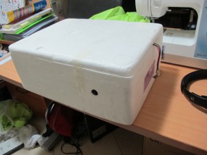
This is a small Styrofoam box that we were very lucky to acquire in a purchase my wife made on the Internet (allergy friendly chocolates). The Styrofoam box is an ex-Broccoli box. It was chosen because the dimensions are almost perfect for fitting all the components and the thickness of the walls is good to allow the cameras to JUST poke out enough.
The boxes dimensions are:-
Length: 385mm
Height: 160mm
Width: 290mm
Wall thickness: 20mm
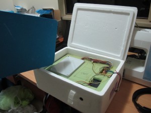
A few pictures of the box (with components within it) are shown below. You will notice that we have some blue foam inside the box. This is to provide a cushion for the components and to help reduce the chance of water getting to components and to also reduce air flows that might take heat away.
Sensors/Communications Electronics
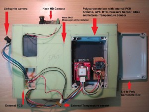
This a fairly complicated part of the payload. It consists of several components:-
- Main electronics polycarbonate box (which is described in another blog)
- External PCB – used to interconnect the Linksprite camera, the external temperature sensor and the Status LED
- Xbee antenna cable
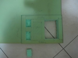
the components are all sandwiched between special water resistant foam-like material purchased from Clarke Rubber and some other foam normally used to make cushions. This material has been chosen because of its ability to cushion the sensitive electronics against knocks, help the payload retain warmth so that the electronics can continue to work at the very high altitudes (30km) it should reach. The foam is very light which is an obvious requirement.
Below are some pictures:-
The “HackHD” camera
The HackHD camera (purchased from LittleBirdElectronics) is installed standalone with it’s own 3 x AA battery pack. We purposely kept this separate from the rest of the electronics to reduce chance of failure of all electronic systems. It is shown pictured below:-
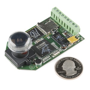
We installed a 32GB Class 10 microSD card, the largest size we can install in the camera to give us about 3.5hrs of video footage. We choose Class 10 because we wanted to be sure that the camera could write to the microSD fast enough. The idea with the microSD is that we can start it up just before flight and if we are able to recover the payload, then be able to play the whole launch from a rather good vantage point.
The Abrasion Jacket
The styofoam container is a great insulator and is light but it does not have the strength to withstand a long possibly windy flight, the balloon popping. So what we do is put this styrofoam package (with all the electronics within it) into a ‘jacket’ made out of spinnaker cloth (ripstop nylon). This is the same sort of material used in kites, yacht spinnaker sails.
We are closely following a design described in the document:-
http://www.parallax.com/dl/docs/cusapps/NearSpace1.pdf
Below are some photos taken during construction:-
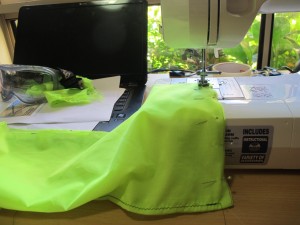
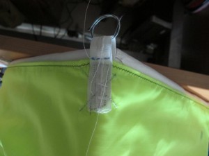
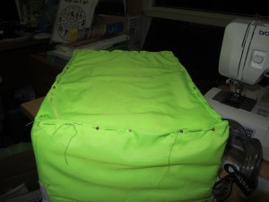
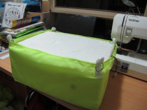
This jacket provides a means of attaching the nylon rope from the parachute to the payload.

My group recently transmitter HD TV 1080 (yes, very high resolution) images on 2.4GHz with a 1 watt transmitter and it should be noted that heat dissipation in the electronics becomes an issue in the stratosphere. With a power consumption of 4 watts, the video transmitter had to dissipate 3 watts. With virtually no air to conduct the heat away, we used external copper foil fins that were kept in the shade and were coloured black. This made use of what little convection we got and also radiated heat for cooling. Please be aware of the issues. We used two fins on the 2 chips that dissipated the most heat. It worked well. Our link used a dish to get good gain and distance and we expect that we would have video to over 100km, but the balloon only got about 70km distance – Line of site.
Also note that we chose circular polarisation to prevent dropouts cause by the payload swinging around. Your payload will probably swing a lot during flight and thus I suggest circular polarisation. The antennas are cheap and they have gain.