Progress

The ‘pretend’ launch (Testing Procedures)

If we had more people launching balloons around Cairns, then attending such events would help to give one the knowledge/experience required to launch a balloon. In the absence of this, we will perform a ‘pretend’ launch.

I’ve been working on a ‘pretend’ launch, where we go through all the motions of inflating a balloon, but we don’t do the final step, and that is ‘let it go’. This I feel is an important part of the project because when we travel 3hrs inland, we don’t want to have to turn around to get a missing part, or pop the balloon when it is two thirds full.

The instructions generated for performing the launch have been mostly done, but there will be several refinements made and there will be complimentary video, pictures to assist in analysing/refreshing our minds on the whole process. It should all be relatively straight-forward, but we leave nothing to chance.

With this ‘pretend’ launch, we will use Helium like at go-live…we will try and keep everything as realistic as possible. We will also conduct a trial ‘cut-down’ to confirm that this part works satisfactorily.

 

Request for launch sent to CASA

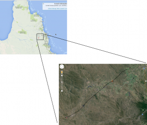
After much thought and investigations, we have filed an application with CASA for permission to a flight about 100km SW of Mareeba. The launch is to be done as a “Light” Balloon and is for a flight on 1st of November 2014.

Below is map showing one such predicted flight. Of course, the actual flight plan varies quite substantially from day to day.

One of many possible flight paths

Unfortunately the application is not going to be straight-forward because while the balloon does meet requirements of a Light Balloon with it’s payload weight, it does not meet the requirement of the balloon diameter (<2m through-out the whole flight).

As you will notice, we have lodged the application with CASA very early on, so as to allow a long processing time, or possibly the lodgement of a second application, should it be required. Hopefully it will not come to this; but do not want to leave anything to chance.


UPDATE: 6th July 2014

That application is in the process of being looked into. Still waiting for some concrete response in regards to what other conditions, exemptions, etc may be required.

The Organising of the Balloon launch (Progress as of June)

The process of organising the launch and finishing of the Balloon payload is taking a long time to do. Many of my work an family commitments mean that I’m only to progress things slowly. The following are the main areas of concern

1. Obtaining a vehicle to transport self and equipment and others to site

2. Confirming whether SPOT3 or SPOT2 is the best Messenger to add to the payload

3. Investigating procedure to fill the balloon

4. Investigating what the best way is to ‘test’ the fill procedure, with least expense, but most realistic setting

5. Touching up on the document for CASA, requesting approval

6. Obtaining a radar reflector

7. Obtaining a spare Totex 800Gram balloon

8. Determining the best way to include Family (esp Jeremy), if the decide they’d like to be at the launch.

As one can see, there is still very much that needs to be done. I am getting a little more confident with these points.

1. Still need to test drive a Toyota Hilux, but thinking that a Ford Ranger will be the one to go for

2. The SPOT3 Messenger in ‘Tracking Mode’ apparently won’t turn off for 24hrs

3. I’ve found a UK site that describes a PVC like http://wiki.ukhas.org.uk/guides:fill_tube

4. I am thinking I will purchase an Air Cylinder from BOX (~$60) and use that as if it were Helium. I’ll need to make sure the same connetions, pressure, regulator are used for it as the He cylinder.

5. I’ve confirmed as long as I’m out side the range of the Cairns Secondary Radar (474km), I do not need a transponder. This means I need to be a LONG way west. Normanton is 505km West

6. The CASA regulations state that for a Medium Balloon, a radar reflector is required. I’ve located one http://www.sky-probe.com/Accessories-Radar_Reflector.html#!prettyPhoto

7. I might have to purchase one through UK again. A bit wasteful to have to buy it through a second purchase…a bit of an oversight

8. Looking at possibly flying family to Normanton and they can hire a car. Will see.


Obtaining a Spot Messenger

As usual, it pays to do ones due diligence before purchasing components; and the Spot Messenger is no exception.

The Spot Messenger will provide a means of locating the HAB while it is below 6500 metres. This will allow us to locate the payload…which would be close to impossible with the GPS because LOS issues might stop us from getting radio reception when it is closing in on the surface of Earth. There is however a potential problem with the GEN3 version of Spot Messenger. It has a feature to power down the Spot Messenger if there has been no activity for 1hr. With a flight duration of 2 hours, it is possible that the Spot Messenger might turn off before it is retrieved! Certainly not ideal. So I am considering purchasing the previous version of the Spot Messenger.

Radio Test 6

Did an extremely successful radio test on the 4th of May from Port Douglas to Buchans Point. The distance between these two locations is 35km. With the help of my wonderful neighbour we were able to :-

  • Confirm that the radio link at 1Watt over 35 km works extremely well, even with HAB in the least optimal orientation
  • Was able to transmit an image perfectly over the 35km link without any problems at the x-modem layer.
  • Was able to get the distance between the two locations (using my mobile GPS co-ordinates and the GPS co-ordinates of the HAB)
  • The cut-down mechanism was initiated and burnt through the rubberband a little
  • Confirmed that the Groundstation new battery configuration is working well.

The great thing about this test is that the Fresnel zone was 65% which means in the real launch, we would expect even better radio transmission results. There is no shadow of doubt that the link distance (as per rfd900 specs) of 40km is reliable and that the max link distance of 50km is probably easily achievable.

I see no reason to continue on with other aspects of the project.

Balloons at Parachute Arrived!

My Parachutes and Balloons have arrived!

I have purchased:-

  • 1 x 800G balloon
  • 2 x 350G Ballons

I got these all from the UK.

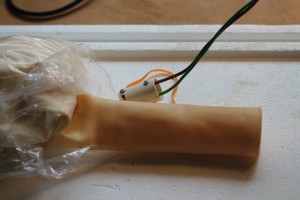
Below a peek at one of them. I haven’t taken it out because I don’t want to damage the balloon.

Throat of Totex 350Gram balloon next to cutdown mechanism


New Ground Station PSU

The problem

I have had issues with the BeagleBone Black turning off after a period of operation. The exact reason I’m not too sure. The rest of the electronics seemed to be on, but I admit I did not check to see if the Sync light remained on the Radio modem.

Some investigations revealed that the BBB PSU voltage was at times dropping down to as far as 4.75 volts. I am pretty sure that the BeagleBone Black has an operating voltage from 4.75 to 5.25 volts. This I suspect is the culprit.

This issue started happening after I pushed the radio up to 30dbi. i.e. the battery has to provide even more power, which I suspect is leaving the BBB with less juice.

I was also concerned now that the BBB battery life, was a lot less than needed for a few good hours of trekking, following the balloon. I decided that an overhaul was required. I did not however, want to go back to two Pb/Acid Gel batteries. Each ways about 750grams, and the two is just too much of a burden.


The Solution

I decided that I would need to remove the Linear Voltage Regulator and batteries.

I initially thought I might be able to use the Switch Mode PSU that was used to power the RFD900 modem, but discovered it is producing 5.3 volts out and the BBB has some protection in it to not turn on. So this didn’t work.

Components of the final solution were:-

  • A 3S LiPo battery – higher voltage and amperage
  • Build and install a Switch Mode PSU

The 3S has a voltage of 11.1 volts (though is more when fully charged). Minimum voltage is 9 volts. This works well because the Switch Mode PSU needs input voltage of ~8 volts or more.

The 3S battery weighs 250grams, which is a lot more than the 75 grams the other batteries weighed, but is considerably less than the Pb/Acid batteries.

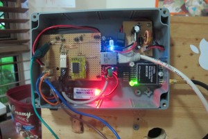
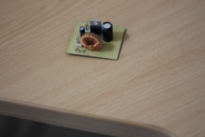
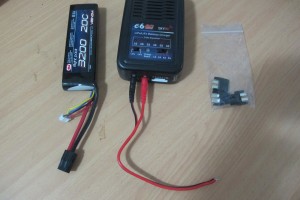
Below are some pictures of the result of all this work.

Ground station with lid removed and fully operational. Batter is at end of brown/blue wires.


The Switch Mode PSU after soldering
New battery, charger and plug adapters


Progress on Electronics

Progress slowed down somewhat due to work constraints, but has sped up a little. The following has been accomplished:-

* Replacement of internal PCB with a custom etched PCB for the GPS and the Relay

* Removal of Arduino GPS shield; replaced with custom etched PCB

* Replacement of switch with better non-bastardized terminals – now using terminals, rather than having wires soldered onto switch

* GPS Antenna now positioned outside box, away from noisy electronics noise by use of a 30cm cable and SMA mounting connectors


After doing all this, I decided that we should repeat the previous ~17km test. Did this test and managed to download 1/2 an image. The GPS worked alot better. The cutdown was initiated, but didn’t burn through the rubberband. I think this was because we didn’t have the connectors plugged in enough.

All this work also resolves problems with faulty battery connectors. We now have mini JST connectors that we plug the batteries into. One thing I did have problems with though was a wire broke off the battery PCB itself. I had to carefully remove some the yellow sticky tape and carefully solder the black wire back onto the battery PCB. I am now taking more care of the batteries and the wires.

Another thing I have done is replace the defunct Sparkfun Li-ION battery charger with a Freetronics one that has decent micro-usb connector…it is soldered through the PCB (i.e. not surface mount). Still waiting for replacement from LittleBirdElectronics.


Batteries for the HAB

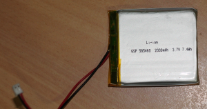
I have purchased two Li-ion 3.7 batteries, each with a current rating of 2000maH.  A picture of one of these batteries is below.

Initial tests with the radio modules at 24 dbi (not the max of 30dbi we will use) saw a running time of 5 hrs and 24 minutes. Well beyond my expectations. I increased the radio TX power to 30dbi and I got running time of 4hrs and 40minutes. I performed another test (After making sure the batteries were complete charged….waiting for the charge light to go out). The batteries connected in series to with a total of 8.17 volts. The run time was 5hrs and 40 minutes. Extremely satisfying.

The battery’s are very small and will fit inside the main Electronics box. This is important because these are Li-ion (not to be confused with Lithium) and their operating voltage is best above -20 degrees

Battery for HAB
Battery for HAB

..though better at zero or above. These batteries will be next to the internal electronics the radio transmitter which should could it sufficiently warm – hopefully. There is a temperature sensor in the radio and near the radio module that will give us a pretty good idea of how the batteries will be copping.

These batteries will be tapped together and stuck to the top of the box and wires will lead to the power board internally.

These batteries are charged with a USB charger. They required approximately 2.5hrs to charge completely.

Radio Test – 4

A radio test has recently been conducted with good results.

Test was:-

* 17.1km

* Using Radio-ACK version of RFD900 firmware

* Air speed of 8kbits/second

Was able to get:-

* Minimal loss of information  (not getting a loss of sync)

* Successfully initiated a cut-down.

* Wasn’t able to get a picture (and didn’t try too long)

* Got a reasonably good RSSI (around about 60/60) not bad considering I had a lot of vegetation in front of me during the test.

Will be looking at doing a 40km test next. Just need to decide how we are going to do this test. I want to have the ‘flight’ batteries connected this time and do away with the battery/inverter set-up.