We are still waiting for “official” approval from CASA. Though we are fairly confident it will be approved. We are proceeding with the final stage of the project, leading up to the launch. We have:-
Confirmed availability of Helium gas and what the latest date is that we can order/purchase it
Sorted out where we will stay on the Friday night (day before the launch). We are fortunate in that it is the ‘quiet’ season and so we can book this accommodation ~ 2 weeks out.
We have found a place that can hire out the Satellite phones at a reasonable price are happy to make the satellite phone booking “tentative”. We will up later to confirm that we require it.
Organised a “pre-flight” meeting.
Confirmed availability of all the crew who will help make the launch possible!!
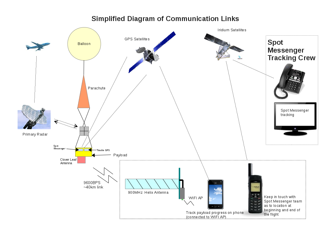
I have decided to do up a small “simplified” picture of all the communication links. It neglects the fact that there is a separate Spot satellite and there are obviously servers where information is stored, but it should be helpful.
There was much thought and time spent trying to find a suitable design/construction procedure for a radar reflector. There are several ones on the Internet, e.g. Instructables one, but they did not seem that practical/suitable. This post describes how our Radar Reflector was built.
The requirements of a reflector are:-
It is light weight
It is able to perform its function regardless of the orientation
It is strong (rigid)
It is easy to construct and not overly expensive.
For materials I decided to use core-flute material (Sold at companies that create signs) and Aluminium tape (50mm x 5metre) from Jaycar and two cable ties.
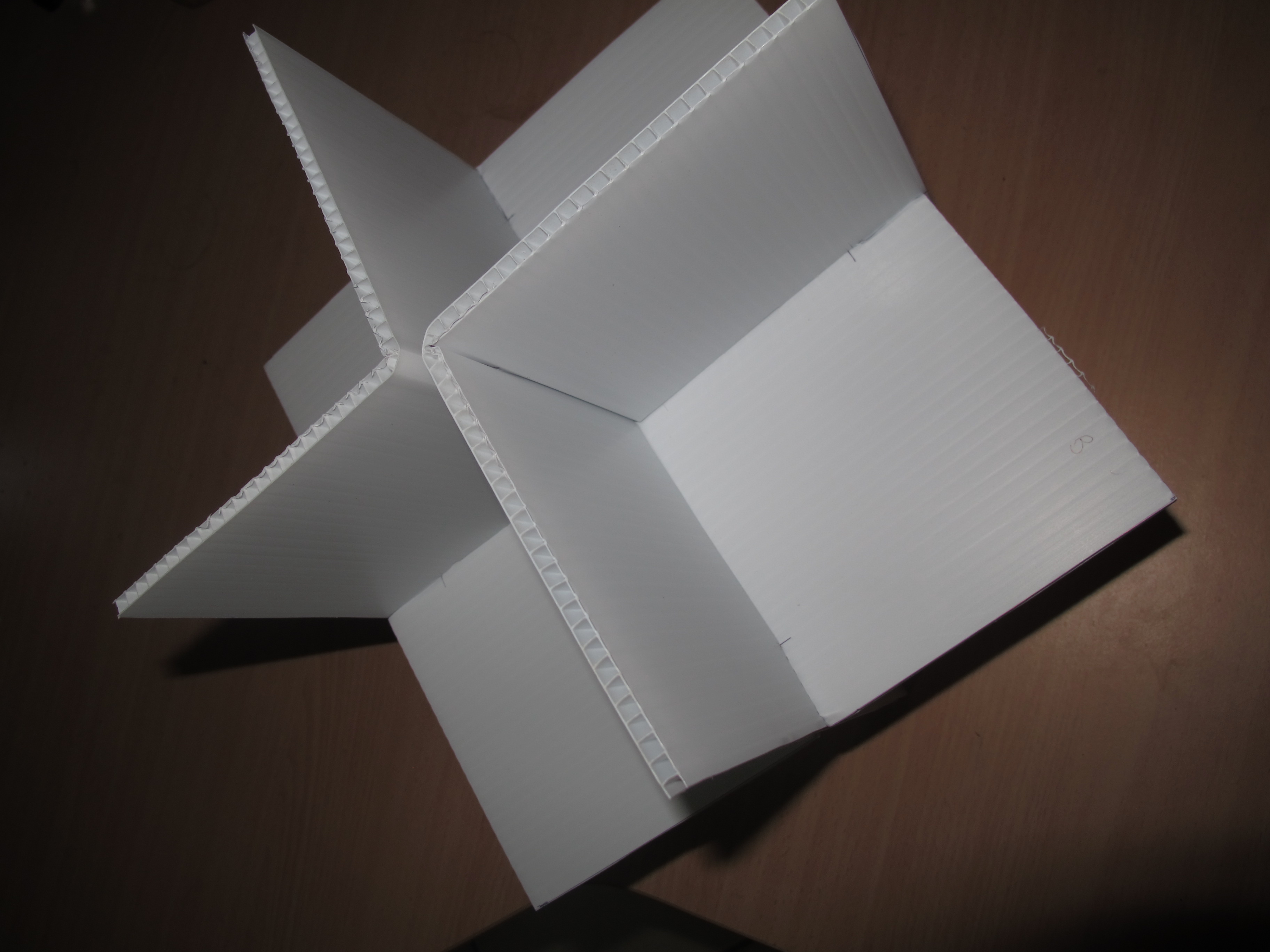
The construction is best illustrated I think using some photos. Please see below:-
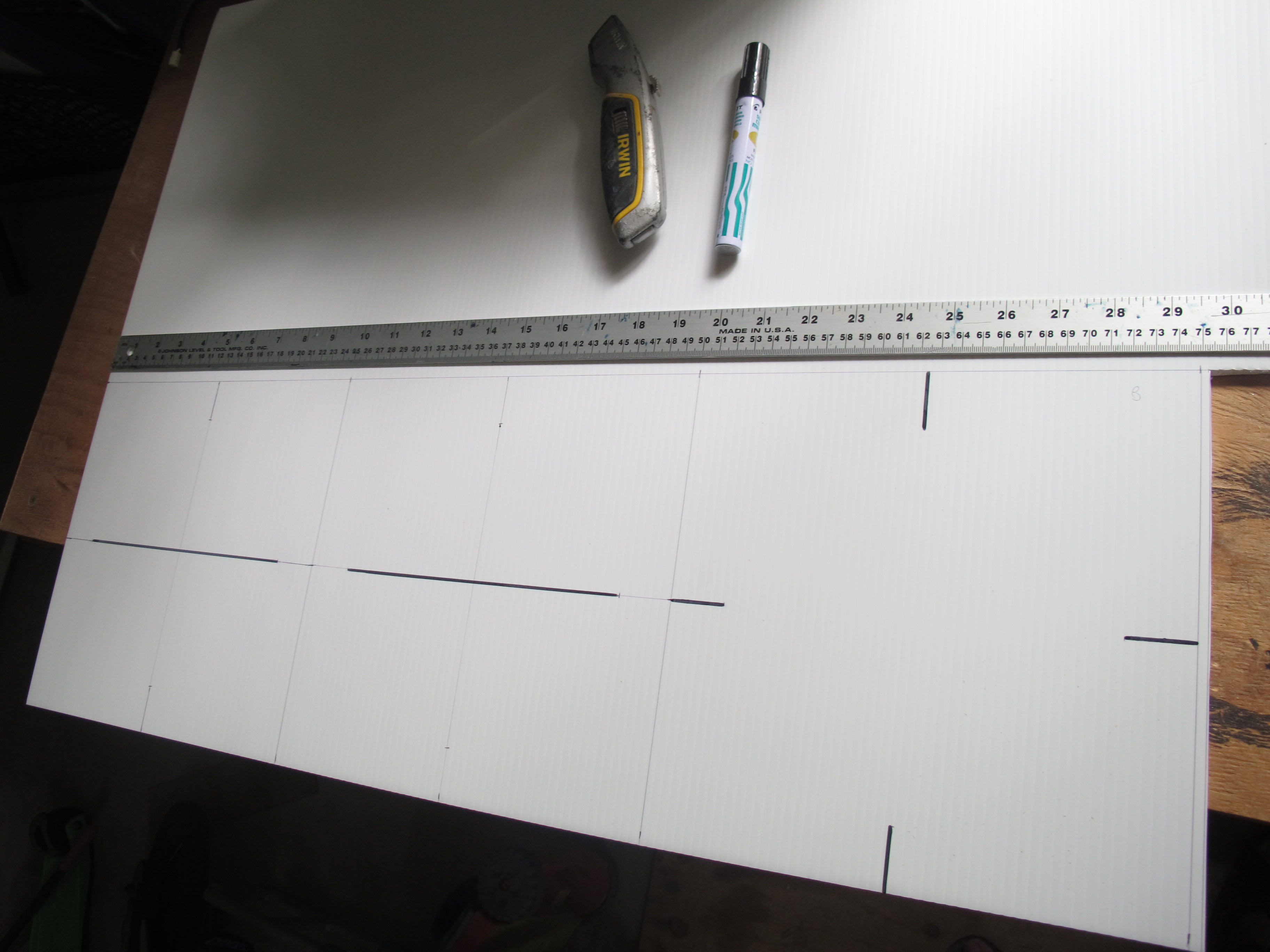
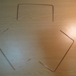
Measuring up – 3 squares – each with side of 250mm
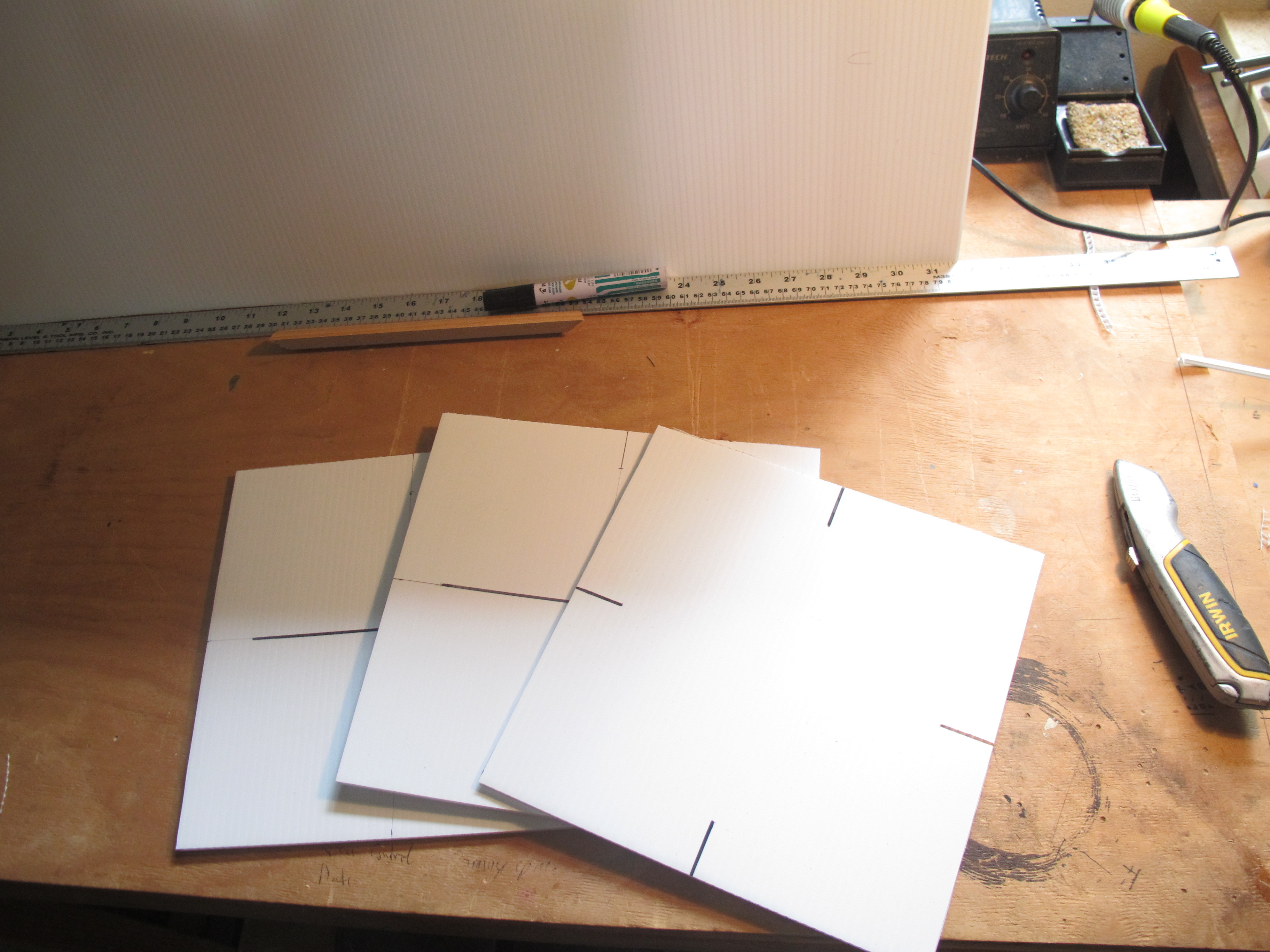
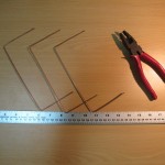
Cut out the squares using a blade. Dark lines indicate where we need to create incisions later on
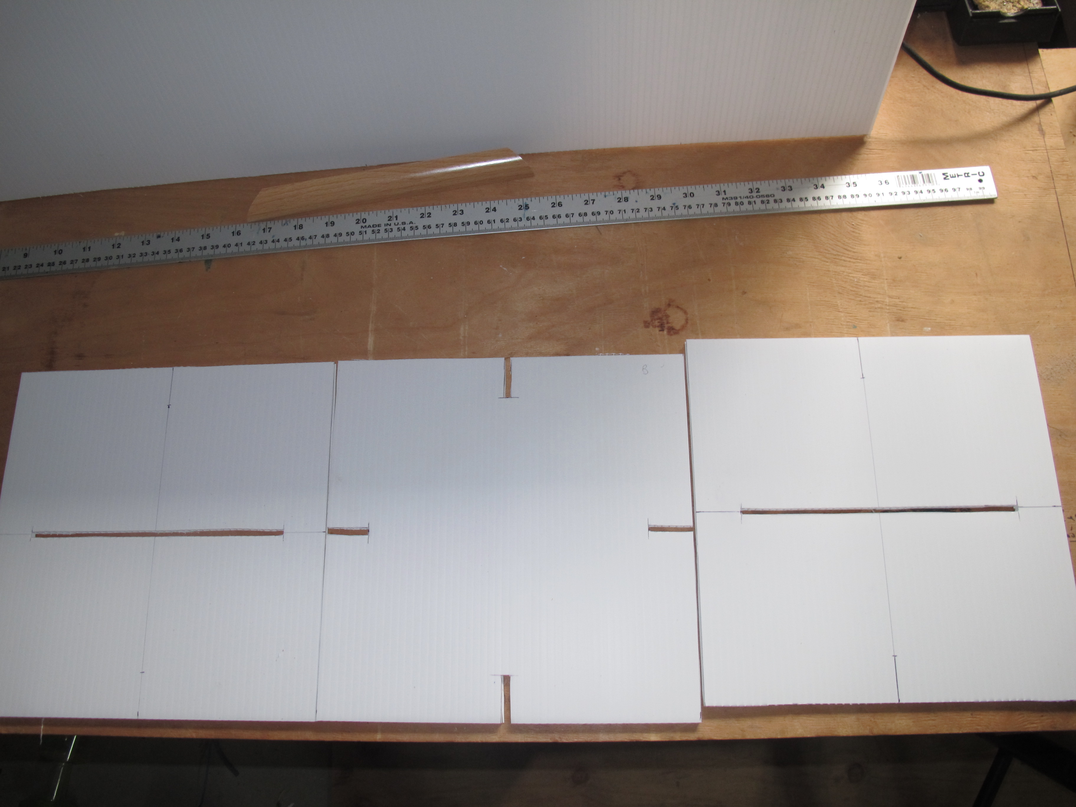
Incisions are made. Incisions are just a little narrower than the width of the Coreflute
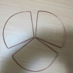
Assemble the three squares. Cables ties later connect two ‘right-angle’ pieces together.Apply Aluminium tape to all faces. Weight is 250grams
We will drill a hole later on in a corner for the thread. Will re-enforce this hole with additional Aluminium tape.
It became obvious that there are probably some ways to make the build process a lot easier. Possibly putting tape on initially before cutting and putting together.
I do also wonder if we “really” need to have Aluminium tape on both sides of the Coreflute; but decided in the end to apply it to both anyhow.
But it is strong/rigid, light, not too difficult to make and inexpensive.
The Balloon can in some cases travel quite far distances and so tracking the balloon needs to be as easy as possible. Much useful data, like GPS co-ordinates, speed and direction are already gathered. We also calculate and display the distance between the ground station and the payload. A graphical representation of the trek of the balloon and the position of the groundstation – a map – would be most helpful. This post describes the steps to accomplish this.
OpenStreetMap (http://wiki.openstreetmap.org/wiki/OpenStreetView) is a very good “free” mapping software that can be installed on a LINUX based system. First we needed to assess this piece of software and its suitability. It was initially installed on a Debian machine using a map that encompasses a fairly large area of the Cairns region, where all balloon trajectories are within. Initial testing suggested it should meet the requirements – it was highly functional and showed the main roads that would be traveled and the API DEV interface is well documented.
The installation process was replicated on a Beaglebone Black. Angstrom Linux was ditched in favour of Debian Linux. Additional space was required, so an 8GB microSD was inserted, formatted and mounted. I had to go through the whole slow process of compiling support for the RTC_DS3232 module and get wireless etc going. Because a lot of additional packages were required, many unrequired packages had to be removed.
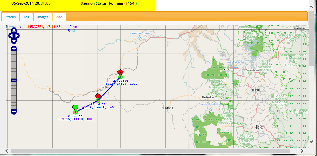
The result, a map that can be viewed offline and show all the waypoints of the balloon and the position of the groundstation when using a phone/pad device with built-in GPS. Below is a screenshot of it.
Example waypoints of imaginary balloon
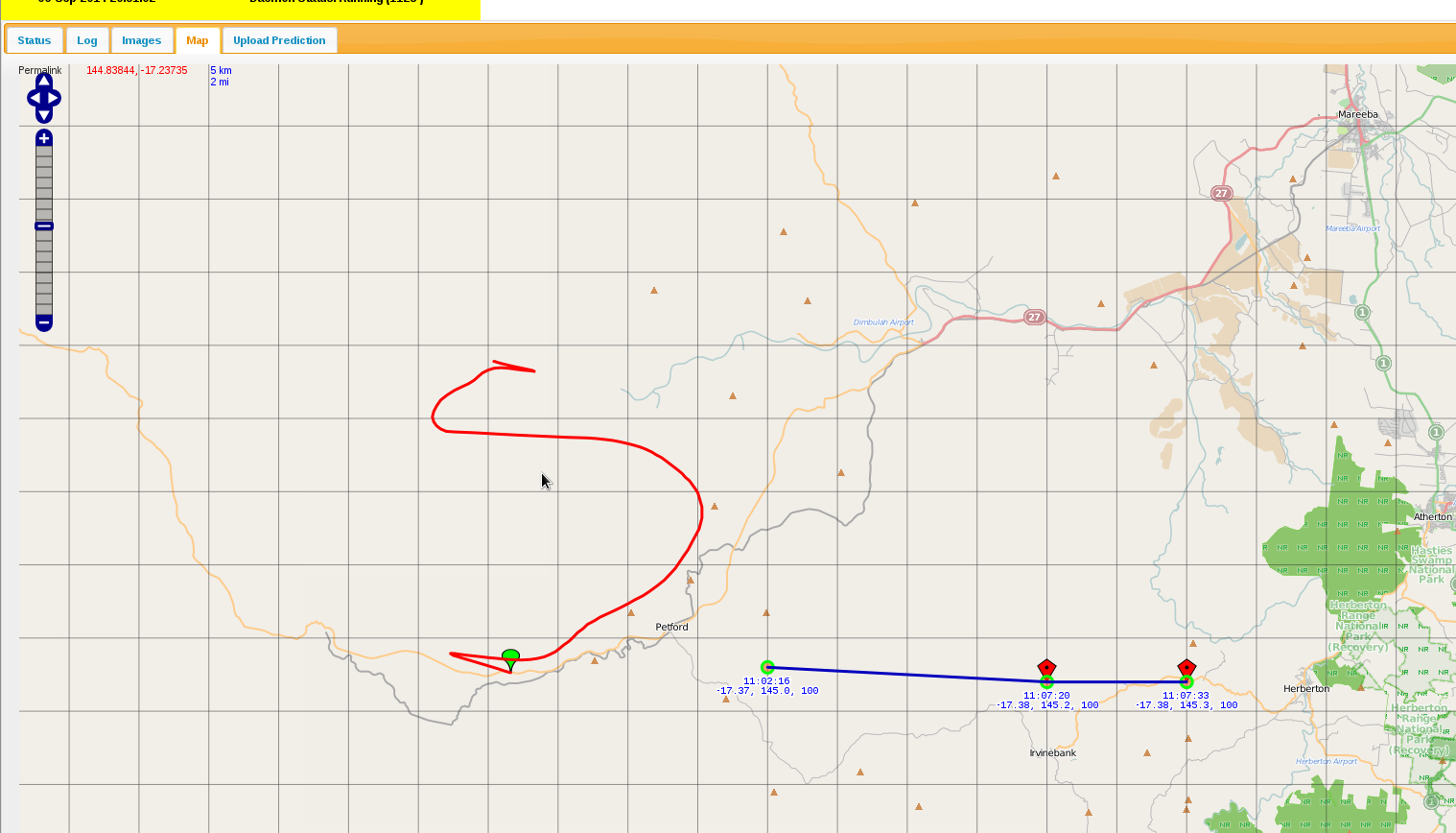
Here is an example with predicted flight path in red.
The interface has been written to show only way points for the current day. Red way points are for the balloon, except for the Green one which is the beginning one. A Blue point indicates the vehicle (when we have a GPS enabled device, e.g. an iPhone). Red path is the predicted flight path and can be generated by uploading a CSV file created on http://habhub.org/predict.
NOTE: We don’t have the blue icon here because this was done from a browser without a GPS device.
A line separates each balloon way-point and time/position are recorded against each way-point.
It can be a little slow at times, but when a map is generated and cached, when it is later recalled, things work relatively quickly. Definitely suitable for what we need it to do.
It has been a while since the last post, so I thought it would be a good idea to provide an update in the progress of the project.
The application for flight is still with CASA/AirServices.
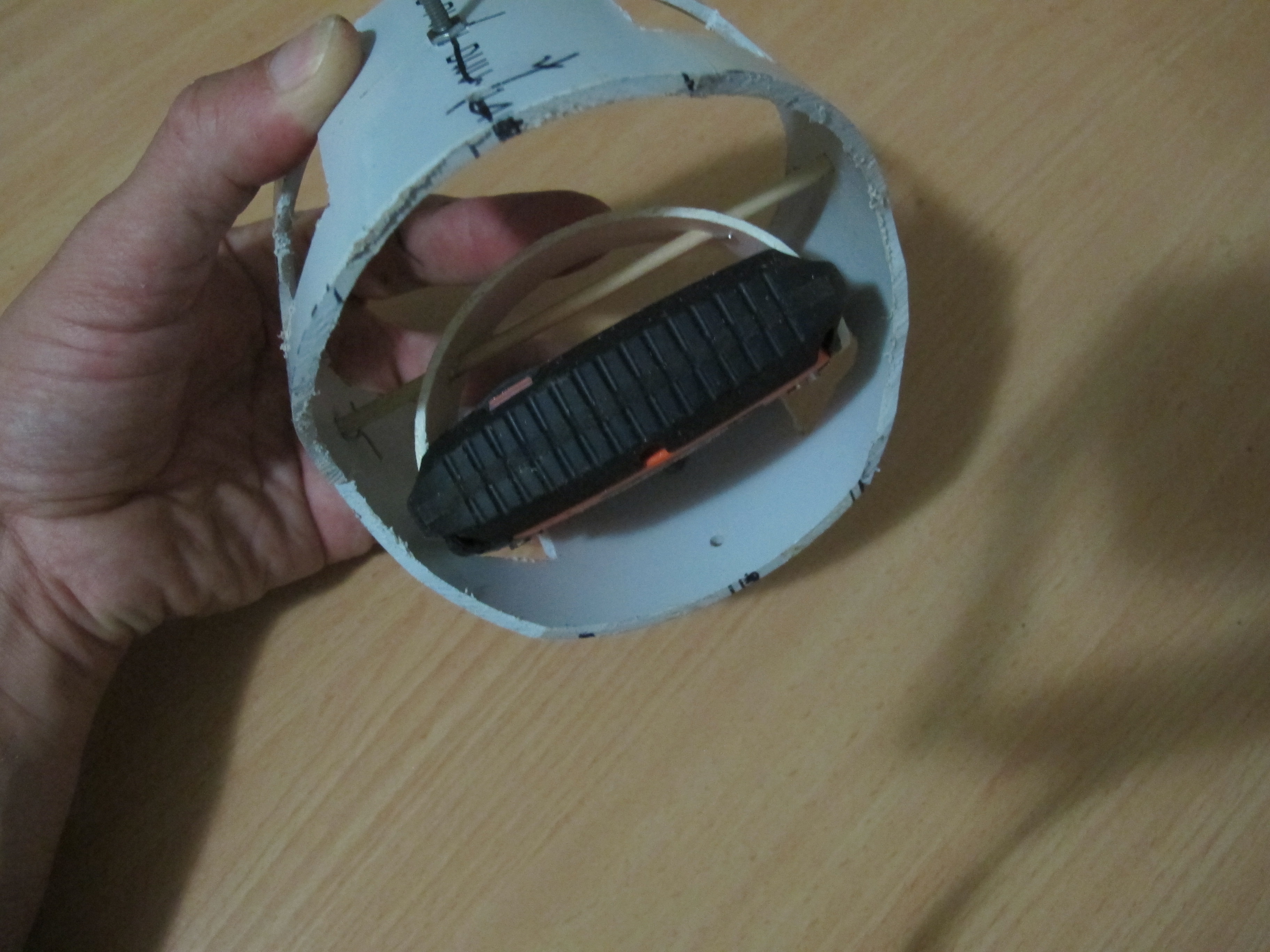
Some good progress has been made in regards to Spot/Gimbal mechanism. A gimbal contraption has been constructed almost completely out of PVC pipe to allow the Spot Messenger to be orientated correctly (upwards), regardless of the orientation of the payload.
Since the project has changed quite a bit, I’ve decided to do up a short video of the payload systems. Please find below.
It was decided after a bit of risk analysis regarding the parachute that it would be advisable to have a gimbal arrangement to ensure that the SPOT Messenger antenna is pointing directly up at all times. This is because Spot Messengers need to be orientated correctly; and if for whatever reason the parachute did not deploy and the HAB did not maintain this orientation for sufficient time, then we may not get any measurements on its decent. [That being said, I did perform a few tests with the Spot Messenger around the wrong way and it did seem to function OK. But we cannot take chances.]
There are several designs that can be found on various sites using hamster wheels and various ways to “attach” a spot messenger. I decided to design one from scratch.
Firstly, I got some 90mm PVC pipe and cut out a 1/3 circle segment about 20mm wide. I was able to fit this snug into the Spot Messenger III slits at each end. The 90mm PVC pipe was just the perfect thickness and the “spring” in the PVC pipe helps to keep the pipe segment “attached” to the Spot Messenger. Then a hole was drilled through this pipe segment and a skewer was passed through. This was all mounted inside a 110mm sewer PVC pipe. This 110mm sewer pipe is cut in various places to allow the easy rotation of the Spot Messenger and to reduce weight. Pieces of wire are inserted in VERY small holes drilled through the skewer to stop
The 110mm sewer pipe segment happens to sit very neatly into a tissue box which we will use to build a fiber-glass device to allow rotation of the whole system inside the payload.
I’ve taken a few pictures of the device and attached them below.
Inside view showing how Spot Messenger is attached
You can see how the PVC gimbal should easily move inside the tissue box.
The HAB payload needs a small/suitable antenna. I decided that it would be easier and a lot more fun to make the antenna; rather than buy one. It would also reduce costs and a lot of additional knowledge and know-how would result.
Materials
Material for this are:-
Material
Quantity
Notes
RG-227U Cable
30cm
2mm solid copper wire
1 metre
I choose thick wire to increase rigidity and to increase bandwidth
Solder
As much is required
Plywood 200mm x 200mm
1
Used to create a “jig”, to which the antenna was created.
Various wood pieces
40mm x 40mm x 15mm
3
Used to create a “jig”, to which the antenna was created.
The cut-down mechanism did not work as well as hoped during the trial launch. This post discusses the issues and proposes a possible solution.
The problem with the cut-down mechanism
The main problem with the cut-own mechanism is that it doesn’t have sufficient power to burn a hole through balloon latex at and near the throat; at least not in a reasonable amount of time. One needs to remember that latex, being a polymer has a lot of strong chemical bonds between atoms. A lot of energy is needed to disrupt them. Also once a hole is made, there is negligible force present at the throat to open the slit to let out a decent amount of Helium gas.
Some testing was done with “best case scenario” where we had a good 6.75volt power supply with minimal hook-up wire connected to cut-down device against thick latex, thicker than what would need to be burnt in reality, but not excessively thick. The Nichrome wire hardly made a dent against the Latex. Even after repeated attempts, we had very little to show.
The conclusion I draw from this is that we cannot rely upon the cut-down mechanism as it stands now. Even if the latex is stretched a little, we cannot expect it to burst the balloon, or even put a hole in it. A different strategy or alternative cut-down design is required.
A new approach
We need to try and melt the balloon envelope where it is thinner and where the strain is greater. Remember that once it is melted, the strain/stresses in the balloon latex envelope are what help to make the hole greater. In the absence of any strain/stresses (near and at the throat of the balloon), there is little chance in the growth of the hole.
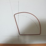
Below is a picture of a proposed system (still yet to be completed). Its segment arm is “spring” loaded so that it should rest against the interior of the balloon surface. At the pointy end is some nichrome wire to burst the balloon.
Alternate cut-down mechanism
We will be inflating another balloon with air this time and simulating a cut-down.
The HackHD camera is a cost-effective light camera chosen for the mission. It does have one drawback; it gets extremely hot during operation. This post identifies the issues this poses and puts forward a possible solutions to _try_ and mitigate these issues.
The Problem
As the payload ascends, it will experience extreme temperatures and pressures. During the initial ascent, there will be a drop in temperature and the pressure will drop slowly. There will be a chance that the camera can cool from radiation and a little bit of convection. As the payload continues to ascend into the Stratosphere, the air pressure drops off to almost zero. Convection isn’t going to work. Radiation of the heat is the only mechanism by which it can cool. There is absolutely no point having a ‘fan’ installed to cool it down because there won’t be anything to ‘blow’ on to the hot chips.
The Solution
We need to ensure that the HackHD can radiate heat as effectively as possible. Remember that we just want to make the HackHD last as possible. It may be close to impossible to allow it to operate the whole time. Ways to address this are:-
1. Keep the journey as short as possible up in the Stratosphere
2. Take video for a few minutes, then turn off to allow it to cool down, then turn it back on again. Or alternatively, take photos instead of video
3. Add heat-sink to transfer heat away, to increase area of surface radiating heat. The flow of heat is directly proportional to the surface area of the object.
The heat Sink
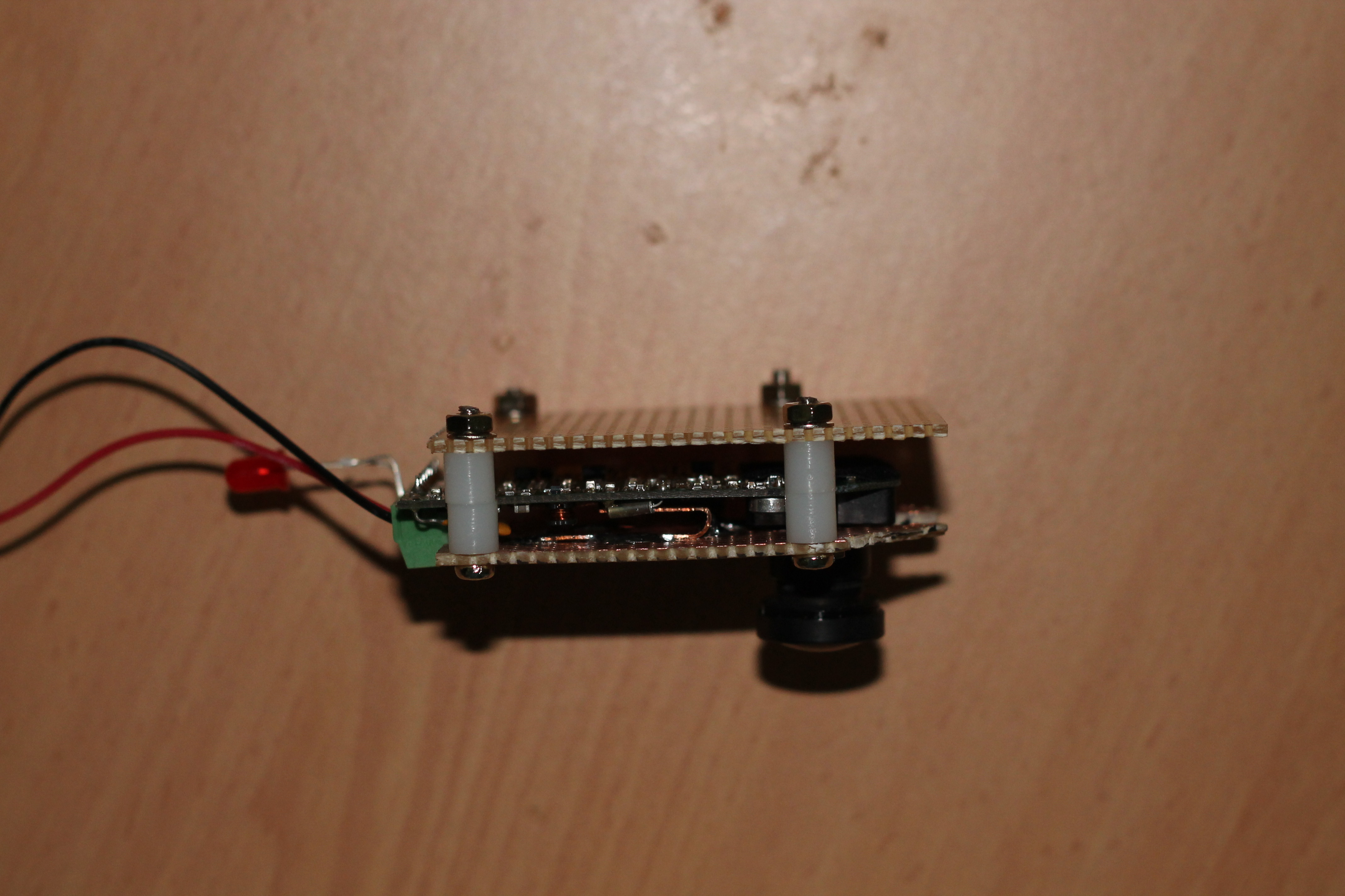
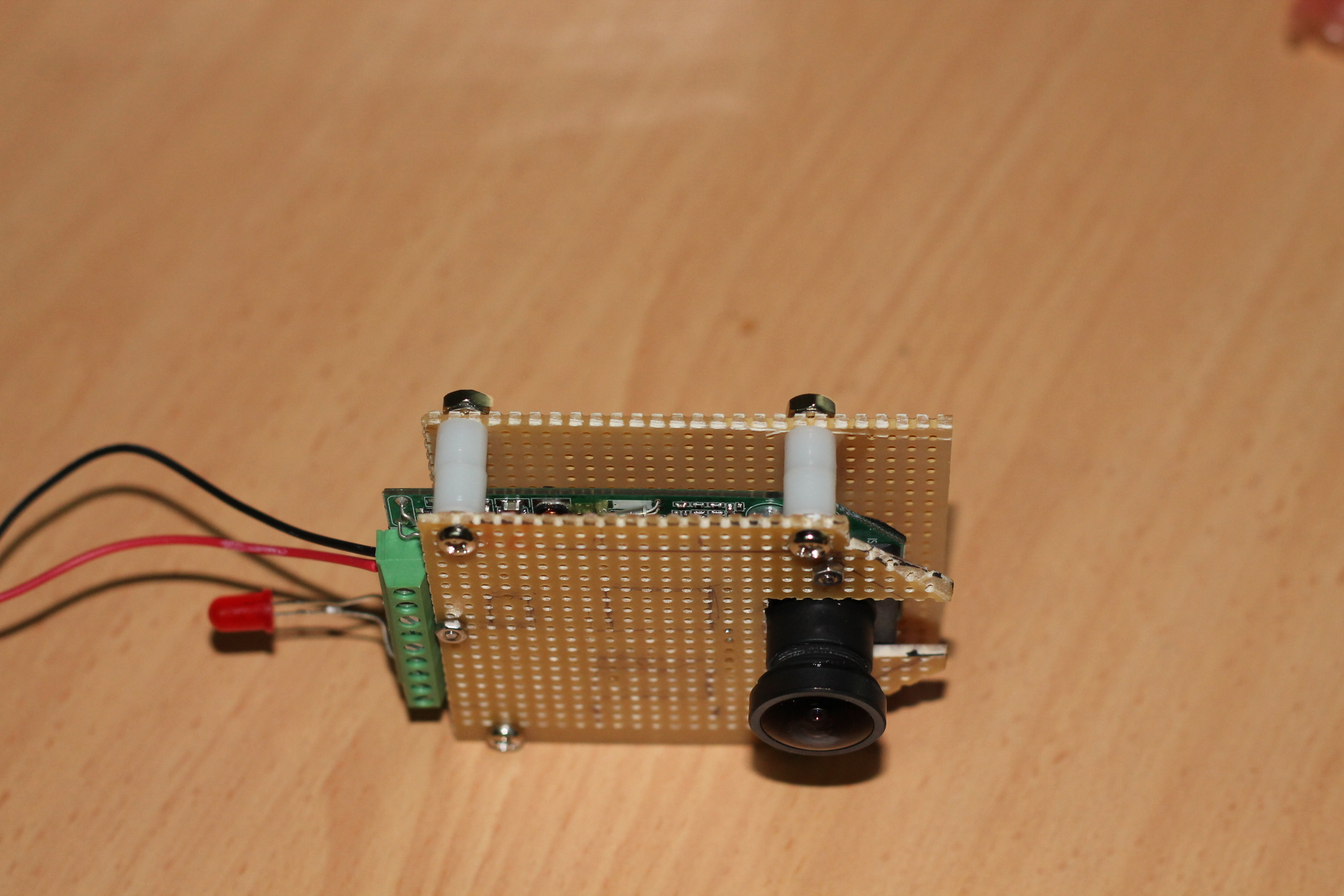
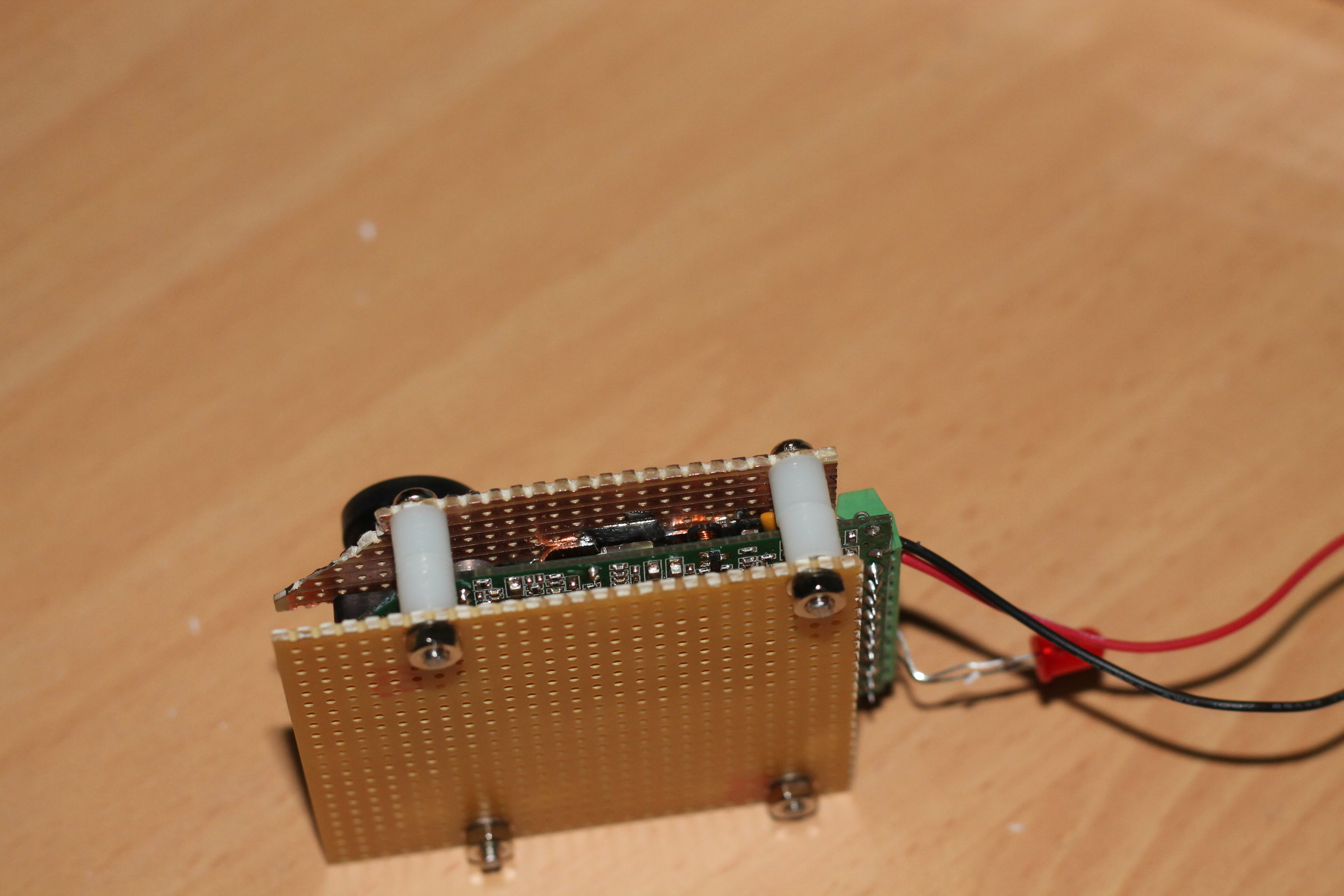
Below are some pictures of the device that ‘hugs’ the HackHD camera.
Look inside between bottom bottom veraboard and HackHD
Bottom viewTop View
We have 2mm screws that connect the veroboard to the HackHD using the three holes it has. We have bent copper plate soldered to the veroboard making physical contact with the three chips. We use heat conducting paste to improve heat flow. We then have another piece of veroboard (no copper on any side) attached to the other veroboad using 3mm screw/nuts. We have two spaces to give an appropriate gap. This last bit of veroboard helps to keep hands away from the underside of the HackHD, reducing chance of damage (static), etc.
It was decided that a “Trial” launch should be performed to:-
Test and refine deployment procedures
Test cut-down mechanism
Confirm all the components work altogether
Familarise the team with procedures
In terms of outcomes, the documented procedures were not too far off what was followed on the day. It does appear that some of the preparation tasks, like inserting the cut-down mechanism will be done on the day of the launch, rather then trying to install the previous night to save time.
It would be beneficial to have an additional team member to assist in the launch, particularly ensuring we follow all documentation and assisting in cleaning up quickly just before we let go of the balloon.
The cut-down mechanism unfortunately did not work as hoped. The first time it fired off, it was unable to burn/melt through the thick throat of the balloon. We moved the cut-down mechanism approximately 10mm further up. We then fired off the cut-down mechanism and a small slit was produced, from which Helium escaped. It did not create the rupture we were hoping for. We eventually popped the balloon manually. What we do know is that if the balloon expands more, then the likelihood of a successful cut-down increases, but it is quite conceivable that a cut-down at a lower altitude may be required, and the balloon may not have expanded much by then. So we will need to put some thought into the cut-down mechanism.
All other components seemed to work:-
Spot Messenger produced 5 way-points, 3 to 5minutes between them. This is quite satisfactory.
HackHD camera worked
Communication worked – good signal strength (210)
LinkSprite camera worked okay (was downloading a picture)
GPS worked well – 7 satellites “seen” very early on.
Temperature/pressure sensors worked
Health indicators worked
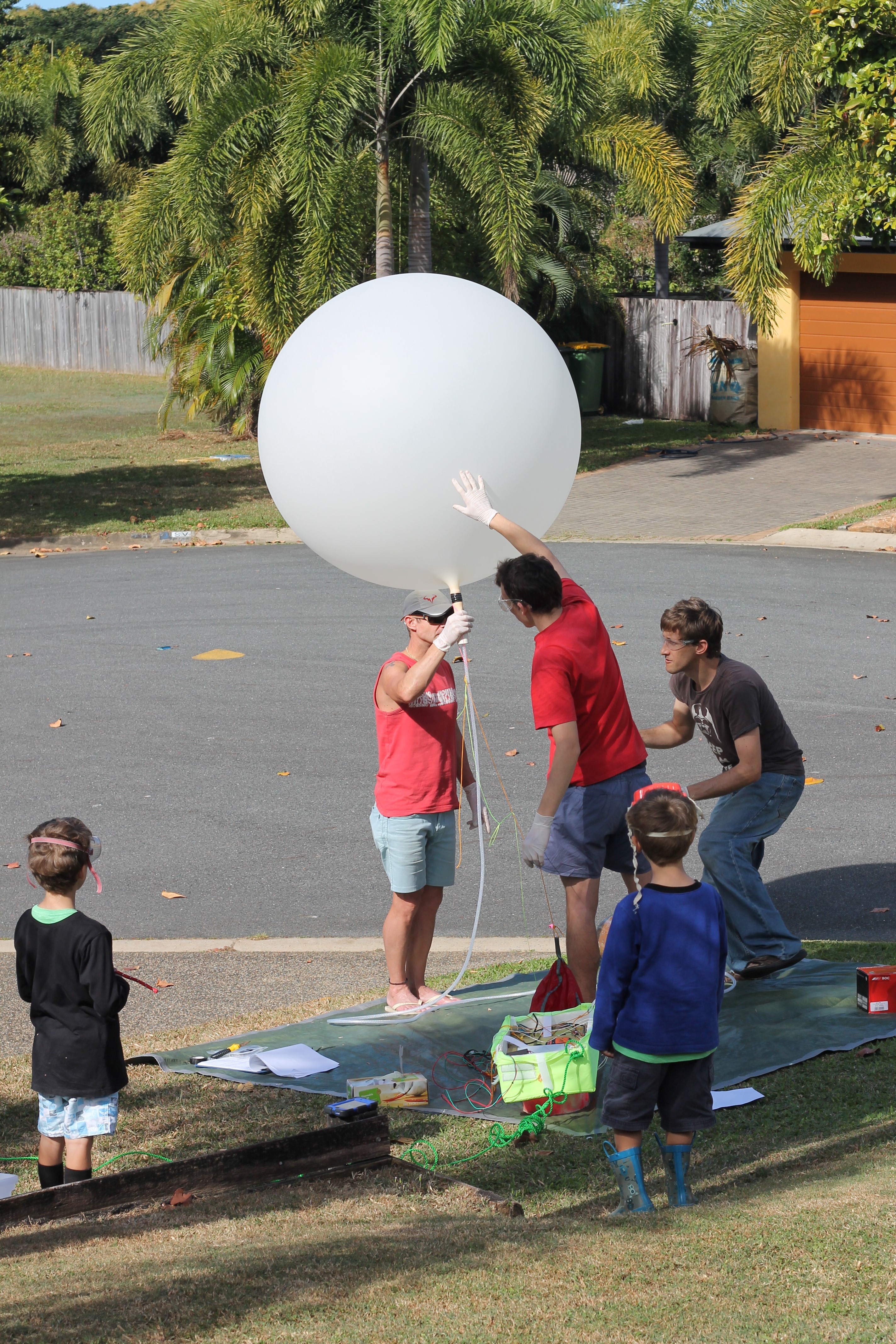
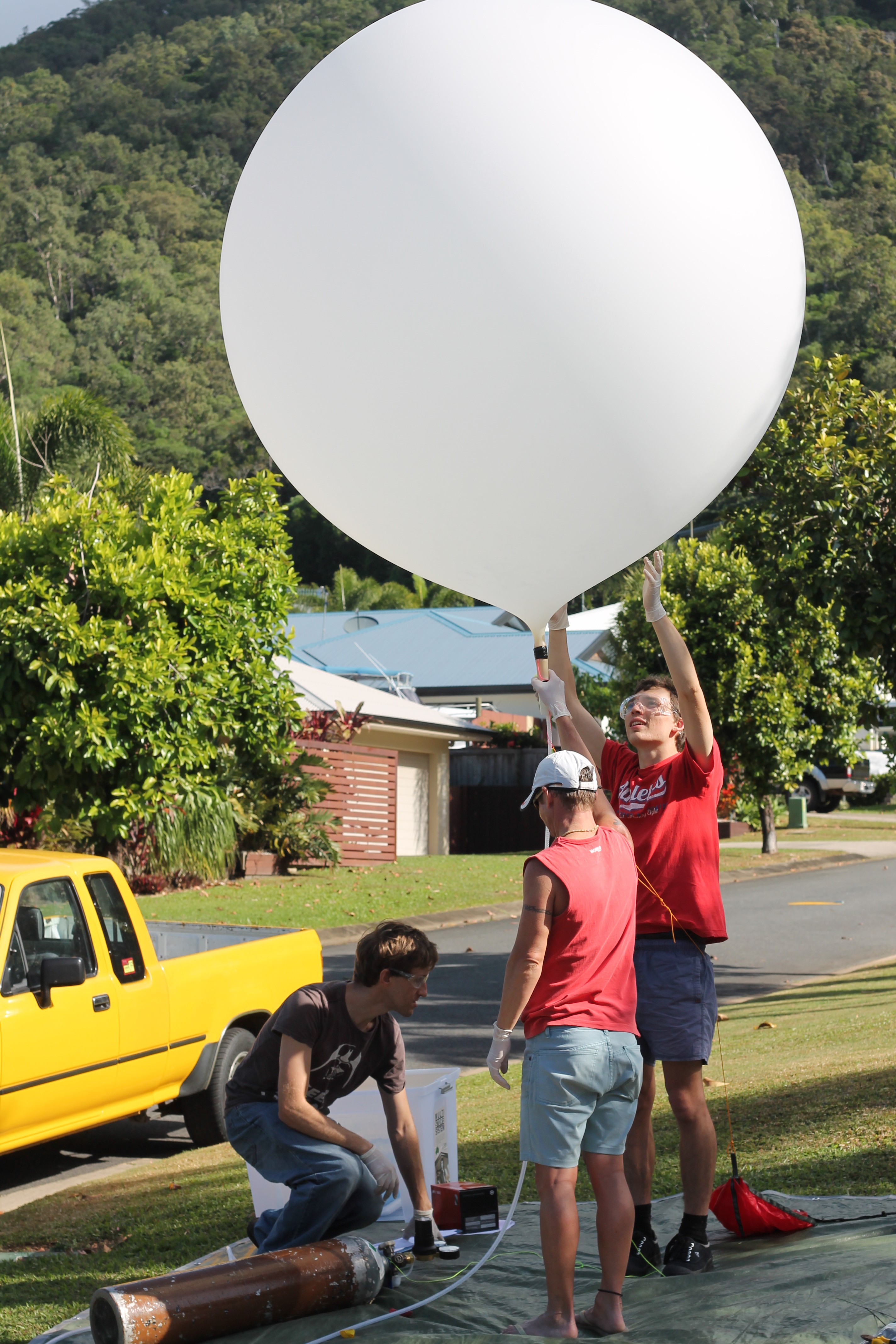
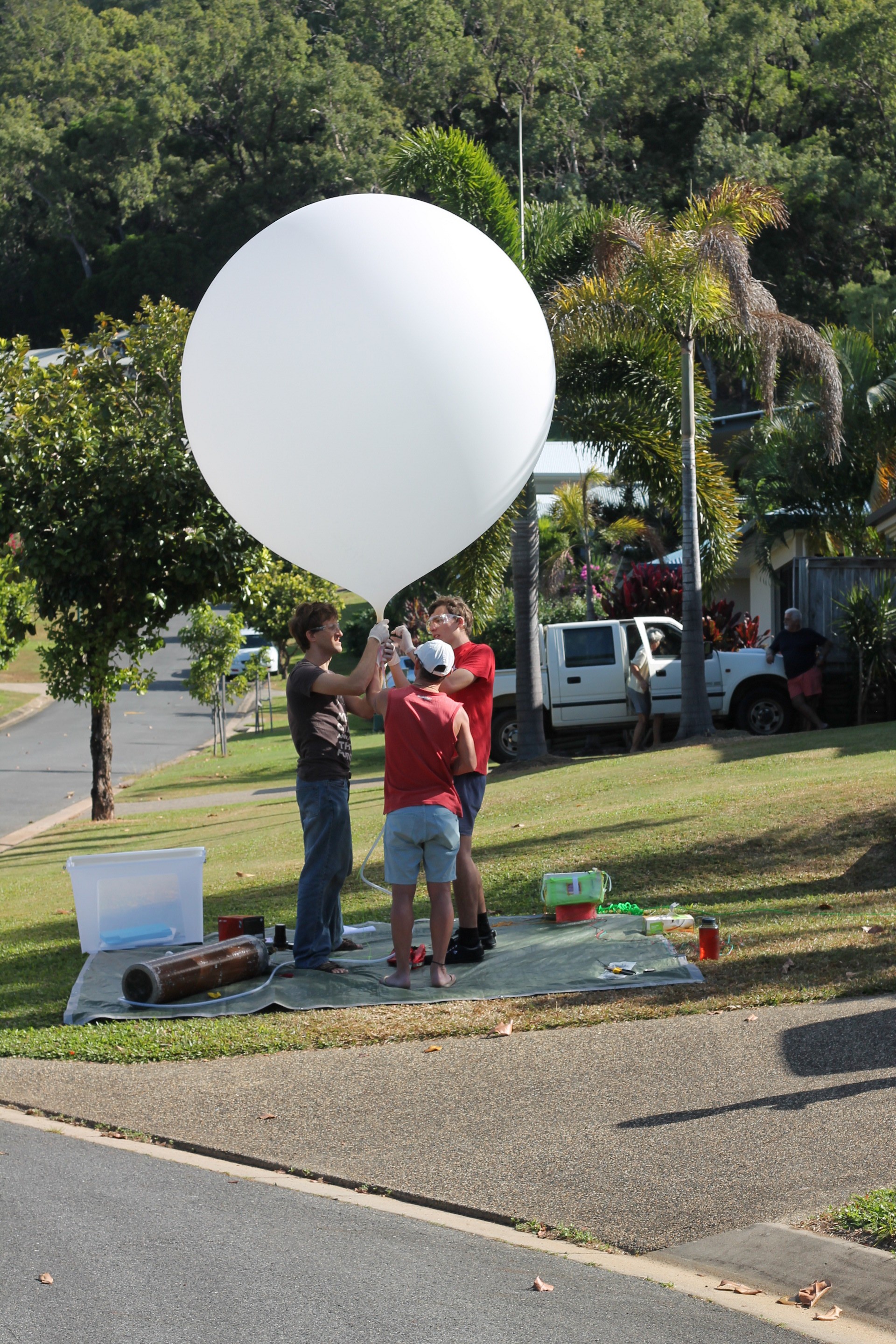
Below are are some photos of the day:-
Helping inflate or watching on with curious eyes
Almost finished inflating
Sealing balloon throat prior to “dummy” launch.
I believe we worked very well effectively as a team. This was helped by an initial brief with the team before the “pretend” launch. I believe it was a very rewarding experience for all involved.
A Spot Messenger account has been purchased and some initial testing has been done to see how the Spot Messenger fairs with the other electronics. Other Balloon launches have been plagued with interference issues between the SPOT messengers and the other Electronics. Initial testing suggests that the Spot Messenger works fine with other electronic components.
The “Extreme” plan has been purchased which allows Messages every 2.5 minutes. This means that when the balloon is descending, at a fairly quick pace, the chance of getting a message through is going to be reasonably large. One calculation had a time of 13minutes to descend from 6500metres to approximately 0, which means up to 5 ‘way-points’.
We will need to do more testing on how forgiving(or unforgiving) the SPOT Messenger is when orientated in a non-horizontal orientation.