New Ground Station PSU

The problem

I have had issues with the BeagleBone Black turning off after a period of operation. The exact reason I’m not too sure. The rest of the electronics seemed to be on, but I admit I did not check to see if the Sync light remained on the Radio modem.

Some investigations revealed that the BBB PSU voltage was at times dropping down to as far as 4.75 volts. I am pretty sure that the BeagleBone Black has an operating voltage from 4.75 to 5.25 volts. This I suspect is the culprit.

This issue started happening after I pushed the radio up to 30dbi. i.e. the battery has to provide even more power, which I suspect is leaving the BBB with less juice.

I was also concerned now that the BBB battery life, was a lot less than needed for a few good hours of trekking, following the balloon. I decided that an overhaul was required. I did not however, want to go back to two Pb/Acid Gel batteries. Each ways about 750grams, and the two is just too much of a burden.


The Solution

I decided that I would need to remove the Linear Voltage Regulator and batteries.

I initially thought I might be able to use the Switch Mode PSU that was used to power the RFD900 modem, but discovered it is producing 5.3 volts out and the BBB has some protection in it to not turn on. So this didn’t work.

Components of the final solution were:-

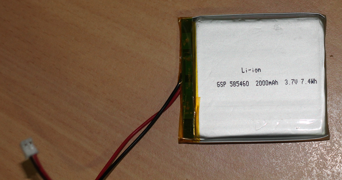
  • A 3S LiPo battery – higher voltage and amperage
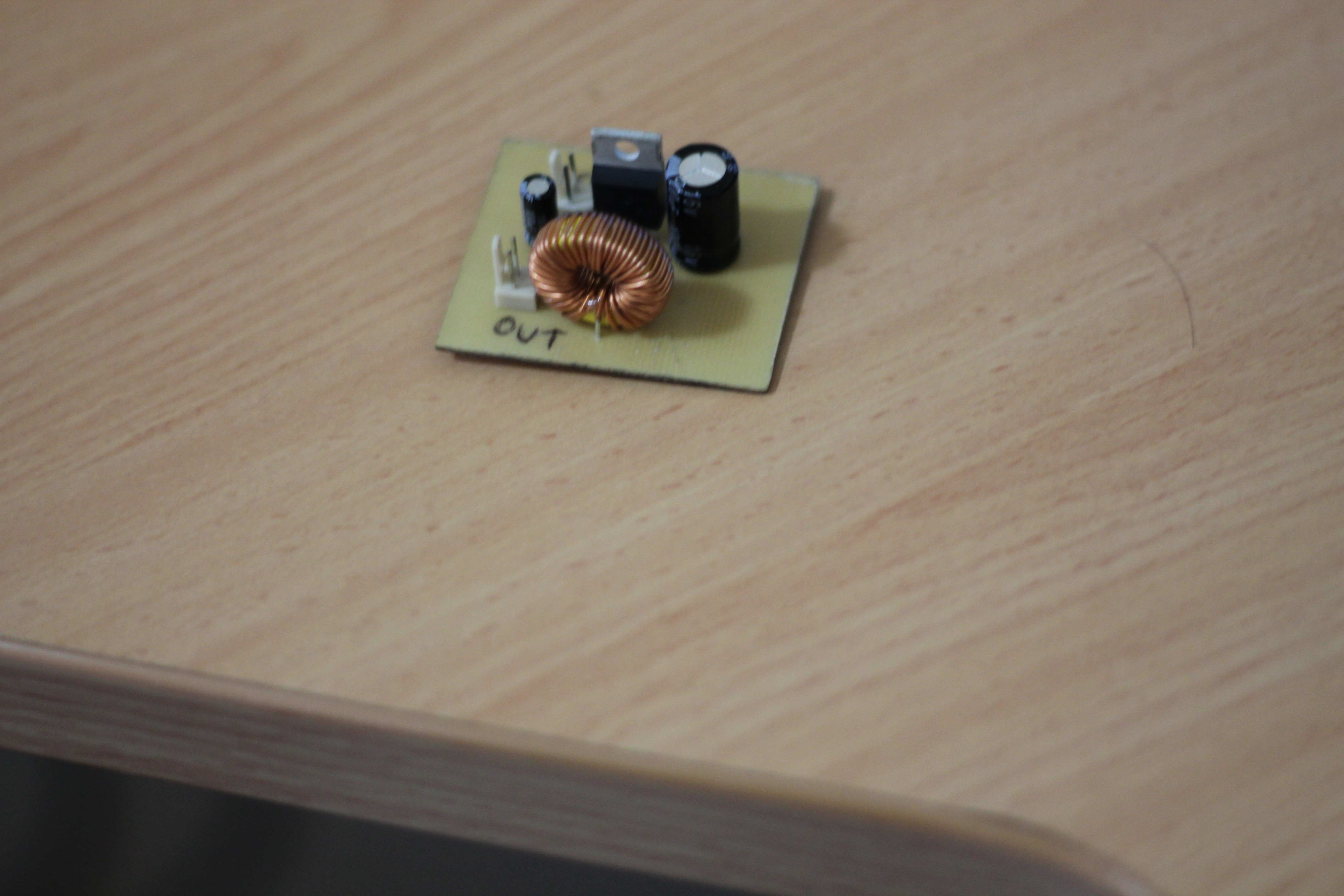
  • Build and install a Switch Mode PSU

The 3S has a voltage of 11.1 volts (though is more when fully charged). Minimum voltage is 9 volts. This works well because the Switch Mode PSU needs input voltage of ~8 volts or more.

The 3S battery weighs 250grams, which is a lot more than the 75 grams the other batteries weighed, but is considerably less than the Pb/Acid batteries.

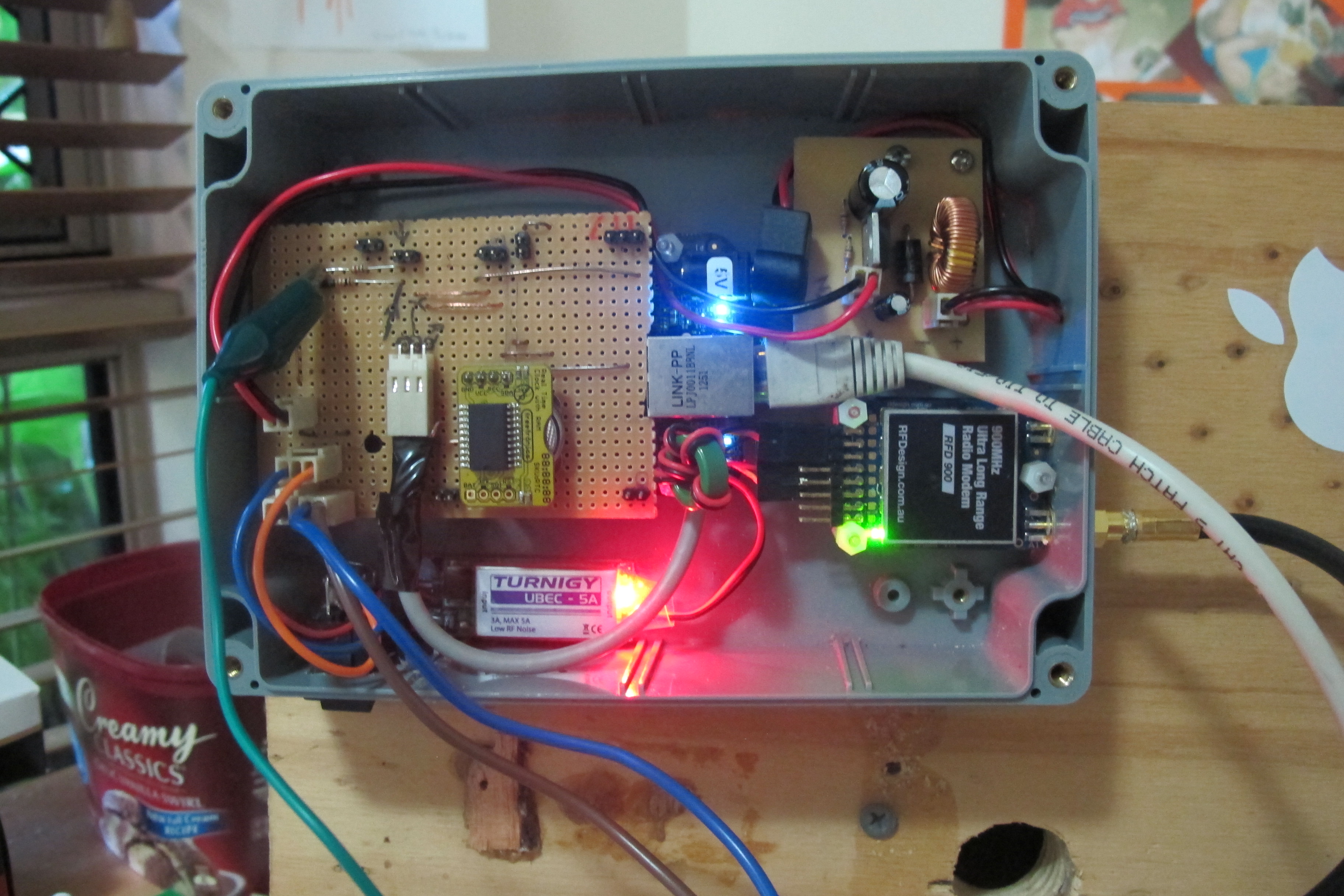
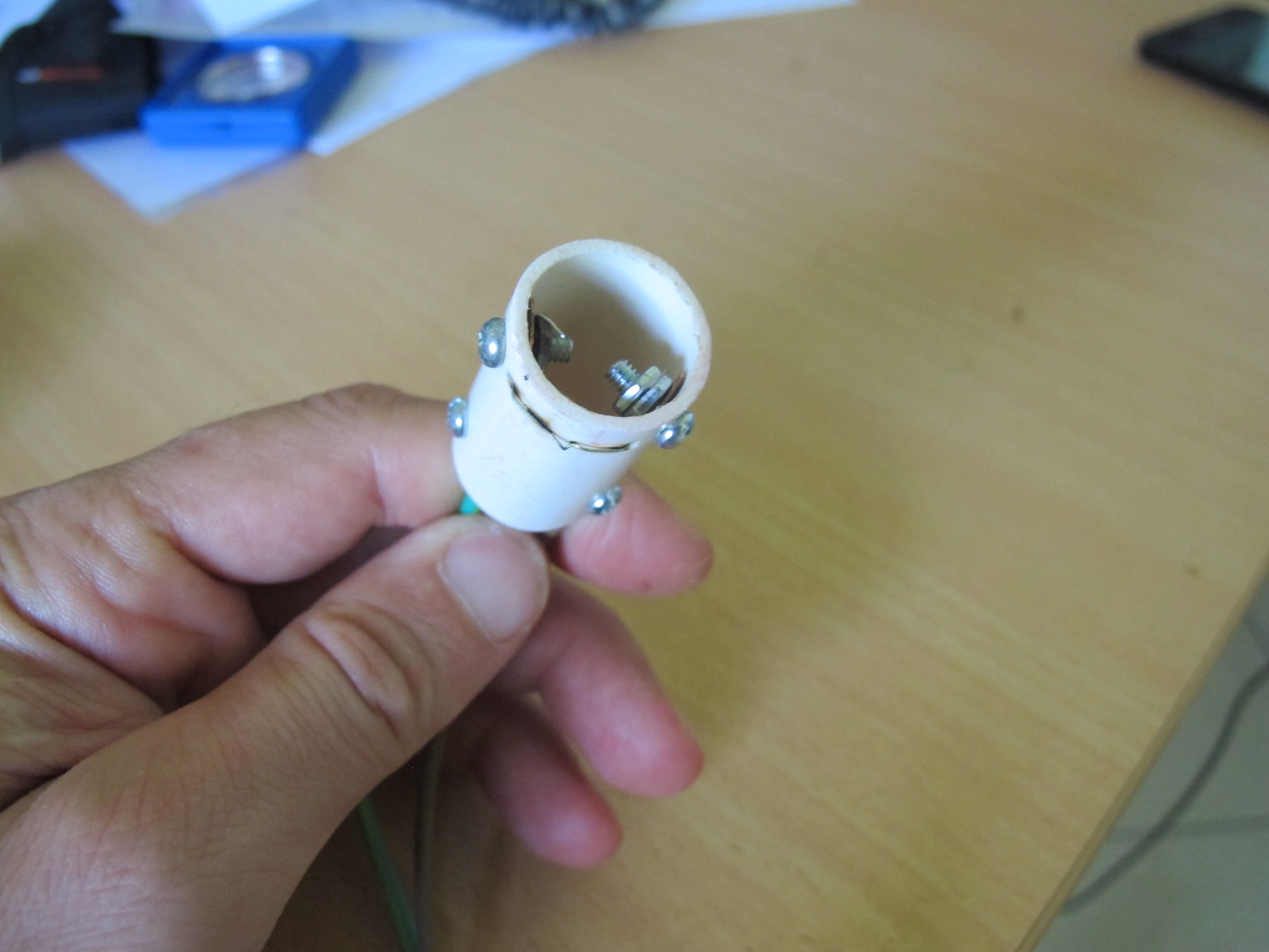
Below are some pictures of the result of all this work.

Ground station with lid removed and fully operational. Batter is at end of brown/blue wires.


The Switch Mode PSU after soldering
New battery, charger and plug adapters


Progress on Electronics

Progress slowed down somewhat due to work constraints, but has sped up a little. The following has been accomplished:-

* Replacement of internal PCB with a custom etched PCB for the GPS and the Relay

* Removal of Arduino GPS shield; replaced with custom etched PCB

* Replacement of switch with better non-bastardized terminals – now using terminals, rather than having wires soldered onto switch

* GPS Antenna now positioned outside box, away from noisy electronics noise by use of a 30cm cable and SMA mounting connectors


After doing all this, I decided that we should repeat the previous ~17km test. Did this test and managed to download 1/2 an image. The GPS worked alot better. The cutdown was initiated, but didn’t burn through the rubberband. I think this was because we didn’t have the connectors plugged in enough.

All this work also resolves problems with faulty battery connectors. We now have mini JST connectors that we plug the batteries into. One thing I did have problems with though was a wire broke off the battery PCB itself. I had to carefully remove some the yellow sticky tape and carefully solder the black wire back onto the battery PCB. I am now taking more care of the batteries and the wires.

Another thing I have done is replace the defunct Sparkfun Li-ION battery charger with a Freetronics one that has decent micro-usb connector…it is soldered through the PCB (i.e. not surface mount). Still waiting for replacement from LittleBirdElectronics.


Batteries for the HAB

I have purchased two Li-ion 3.7 batteries, each with a current rating of 2000maH.  A picture of one of these batteries is below.

Initial tests with the radio modules at 24 dbi (not the max of 30dbi we will use) saw a running time of 5 hrs and 24 minutes. Well beyond my expectations. I increased the radio TX power to 30dbi and I got running time of 4hrs and 40minutes. I performed another test (After making sure the batteries were complete charged….waiting for the charge light to go out). The batteries connected in series to with a total of 8.17 volts. The run time was 5hrs and 40 minutes. Extremely satisfying.

The battery’s are very small and will fit inside the main Electronics box. This is important because these are Li-ion (not to be confused with Lithium) and their operating voltage is best above -20 degrees

Battery for HAB
Battery for HAB

..though better at zero or above. These batteries will be next to the internal electronics the radio transmitter which should could it sufficiently warm – hopefully. There is a temperature sensor in the radio and near the radio module that will give us a pretty good idea of how the batteries will be copping.

These batteries will be tapped together and stuck to the top of the box and wires will lead to the power board internally.

These batteries are charged with a USB charger. They required approximately 2.5hrs to charge completely.

Radio Test – 4

A radio test has recently been conducted with good results.

Test was:-

* 17.1km

* Using Radio-ACK version of RFD900 firmware

* Air speed of 8kbits/second

Was able to get:-

* Minimal loss of information  (not getting a loss of sync)

* Successfully initiated a cut-down.

* Wasn’t able to get a picture (and didn’t try too long)

* Got a reasonably good RSSI (around about 60/60) not bad considering I had a lot of vegetation in front of me during the test.

Will be looking at doing a 40km test next. Just need to decide how we are going to do this test. I want to have the ‘flight’ batteries connected this time and do away with the battery/inverter set-up.

Ground Station Power Supply Modifications

I initially used a 3amp LM7805 regulator to provide the 5 volts to the Beaglebone Black (BBB). This regulator will not work unless the input voltage is at-least 6.5 volts. So a 6 volt battery is not much use. So the original configuration had 2 x 6 volt batteries (in series) producing 12 volts which meant that the regulator was generating a LOT of heat. Very wasteful and not good if we have to go out to places where it is very hot and the regulator gets too hot.

I discovered that the is a regulator that has lower voltage offsets, about 0.5 volts. LM2940CT-5. When the input voltage drops below 5.5 volts, the output voltage is INPUT VOLTAGE – 0.5V. This device can only supply 1amp. I measured the current draw by the BBB and discovered that it was only about 60 mA! Of course, there could be fluctuations that my cheap meter can’t pick up, but obviously 3A is probably overkill. So I switched the LM7805 with the LM2940Ct-5 and it functions very well, off just one 6 volt battery. I’ll continue to do tests to see how long the groundstation works for off one battery, but I expect it to be pretty long.

This means that the groundstation should be more reliable and will weigh less which will be good for when we track the High Altitude Balloon.

Creating the Balloon cutdown Mechanism

The cut-down mechanism is an extremely important component of the high altitude balloon. Getting a reliable cutdown mechanism is something that was considered difficult. Initial thoughts were to have some external ‘sleeve’ that would wrap around the balloon throat, using a rubber band, or string, velcro or some other material to keep it mated to the balloon. It was however decided that a piece of PCB tube inserted into the balloon to provide a means of attaching the payload could be modified to provide a way to bring a Nichrome wire in touch with the balloon.

The only issue I can see is tying of the bolloon end to stop the Helium gas from escaping. The wires _may_ lead to gaps being present. However if we have sufficient cable ties, each tied up sufficiently, and twist the balloon end around the wires, we should be able to stop any significant amount of gas from leaking.

Take a look at some of the pictures below.

Top view of cutdown mechanism showing Nichrome wire
View from the bottom of the cutdown mechanism with wires coming out.


Initial tests show that 6 volts is more then adequate to get the nichrome wire red-hot in a few milliseconds. Enough to heat and burst the balloon.

Current flowing through the wires was measured at about 3.5amps.


Installing the new GPS Module

I’ve realised the that the current GPS module only goes up to about 18km. This is not high enough. So I discovered a module that can go up 50km. This module is different from the current one because it doesn’t come with an antenna built-in (on top of it) and it is definitely not a module you can easily get up and running.

The module also needed some TTL converters to convert 3.3v to 5 volt and the 5 volt to 3.3volts. This all takes up a lot of realestate so it became apparent that we need to mount the new GPS module on its own in the PolyCarbonate box, away from the Arduino (where the old one was installed).

Below is a picture of HAB electronics box with new GPS module.

Install of new GPS module in HAB Electronics Box

The GPS module is mounted about 1cm above the PCB below it and below Serial Voltage level converter. The board requires 5 v, 3.3v, ground RX and TX.

The antenna is attached to the top of the Arduindo GPS shield using double sided tape. I actually had a problem with the antenna shorting out wires on the Arduino initially. All was okay.

Radio Test 3

I’ve devised my own firmware for the RFD900 with changes I shall not divulge here. Fortunately the changes have been effective. I’ve been able to download an image 4.5km away in 8 minutes. The link was substantially more stable. It was extremely pleasing to start to see some success after such a very dis-satisfying start.

There are many enhancements that I still wish to make to make use of the hardware/software easier for myself, in terms of ease of use and in terms of getting more feedback, so I know how ‘well’ it is performing.

Testing of Radio Components

The project has stalled some what as I test and become accustomed with the new RFD900 modems. Many problems have been discovered during the testing of these modems.

1. There seems to be issues at low bauds with TX (I want to use low baud rates so I have increased sensitivity

2. I’ve been getting RX, essentially corruptions in the incoming packets…losing packets.

3. I’ve found that X-Modem transfer of images just dies when it hits some problems.

It became obvious that I needed to look not only at my software, but also that of the radio modems.  I decided that I would stick with the Open Source version of the software (rev 1.X) as I could go in at my leisure and look for issues in the code…and fix them…or atleast get a better understanding.

I managed to alleviate some of the RX issues by disabling USE_TICK_YIELD

I discovered that if I packed only one byte into the TX FIFO of the radio (rather than 4 bytes at a time), I removed my TX errors.

I discovered that the routines that determine how much data we can pack in, did not take into account that with ECC enabled, there are more trailer bytes.

I discovered that if I missed the start of the x-modem packet, the X-modem perl module would not wait for all the ‘bits’ of the failed packet…and so it would time out and end the transmission almost straight away.

In the end I decided to use:-

S0: FORMAT=25
S1: SERIAL_SPEED=57
S2: AIR_SPEED=16
S3: NETID=25
S4: TXPOWER=12
S5: ECC=1
S6: MAVLINK=0
S7: OPPRESEND=0
S8: MIN_FREQ=915000
S9: MAX_FREQ=928000
S10: NUM_CHANNELS=50
S11: DUTY_CYCLE=100
S12: LBT_RSSI=0
S13: MANCHESTER=0
S14: RTSCTS=0

It seems to work well with initial test around the house and up the street. It is also a bit faster then the 8kbits/second.

of course, things might change after I do a bit more testing.

More improvements to the web interface app

I’ve managed to add functionality to the page to display they mobile phones GPS coordinates on the web page on the status page. I’ve also coded the status page to calculate a few interesting numbers.

1. The distance (Across the surface of the earth) from the user’s mobile phone to the HAB

2. The LOS from the users’s mobile phone to the HAB (i.e. we take into account the altitude)

3. The bearing  – (direction from the user’s mobile phone to the HAB).

Obviously, the user needs :-

* Use a mobile phone with GPS

* Have GPS enabled…not the WIFI as a means of locating itself

* Allow sharing of location with the browser

This information will be very important when we need to track the HAB! I’m pretty happy with that!