Below is a thank-you video…to all the people who helped make the mission a success.
This is not how it ends….the adventure has only JUST begun…..
Cairns Australia High Altitude Balloon
High Altitude Balloon Australia

Below is a thank-you video…to all the people who helped make the mission a success.
This is not how it ends….the adventure has only JUST begun…..
In this post is a graph of internal and external temperature (all in Kelvin) against time. The graph we see is very much expected and we are fortunate it was like this as the batteries would not have worked terribly well if it dropped too much.
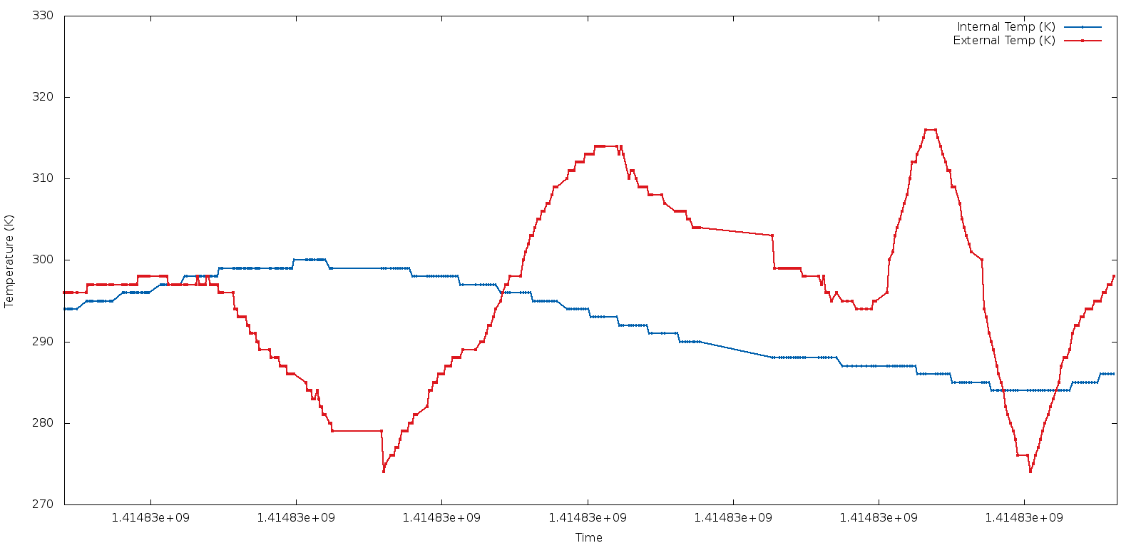
The external temperature reading themselves aren’t what I’d expect. Temperatures go down below zero in some parts of the atmosphere. I put this down to the fact the temperature sensor is mostly enclosed in some Areldite (glue) to reduce chance of shorting of leads in ‘wet’ environment. We are also going very quickly through the various zones of the atmosphere which means we might not have enough time for the temperature to settle.
What is interesting is the lag between internal temperature and external temperature. The Internal temperature was recorded inside a Polycarbonate box, which inside was generating some heat itself – majority from the RFD900 radio and other electrical components.
Overall, the flight went exceedingly well. Over the course of the next few weeks, we will go through some of results/measurements.
We sum up in this Post what went well and what didn’t go so well.
From these observations, we will determine what improvements can be made for future flights (should we conduct future missions).
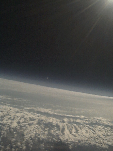
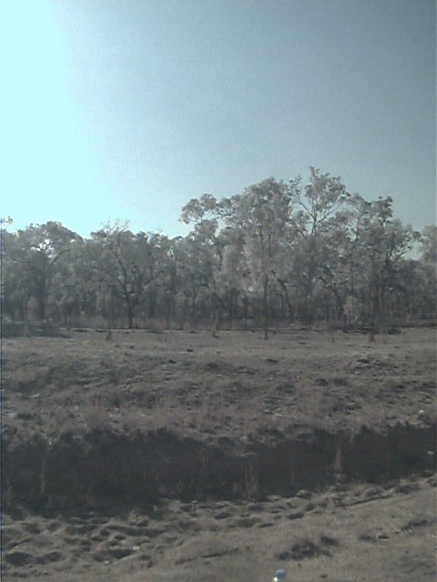
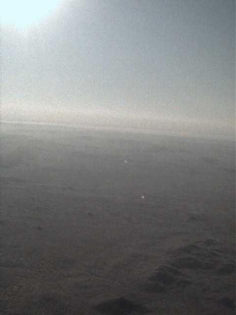
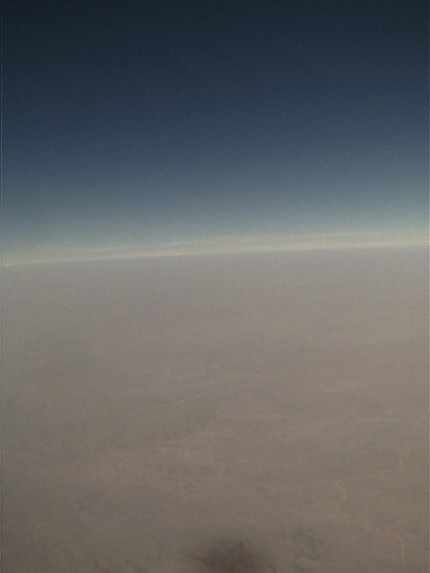
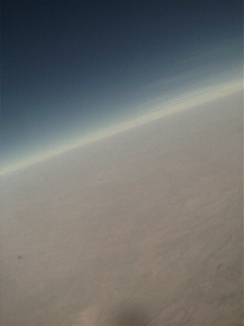
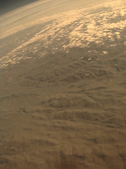
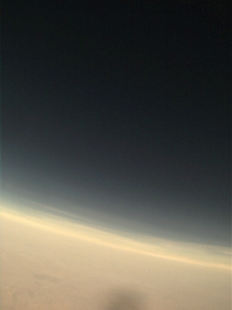
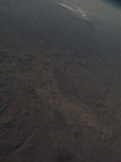
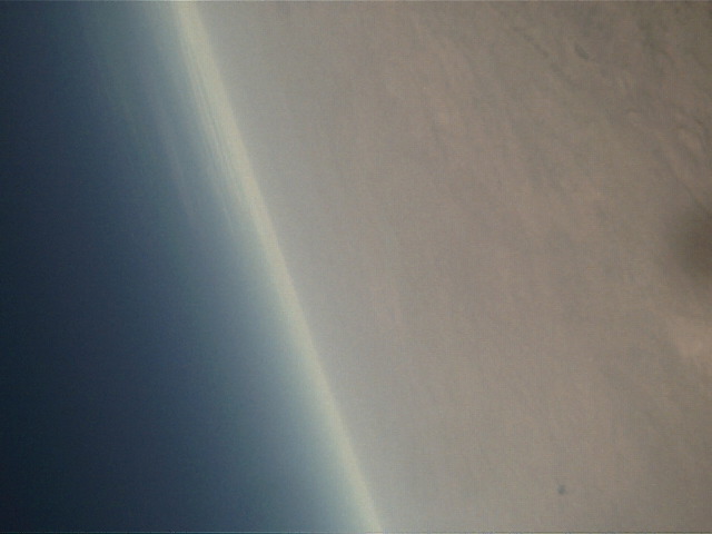
More pictures taken aboard the payload are below:-


We performed the Balloon Launch today!
Unfortunately, we haven’t been able to recover it because it is so far off the “beaten” track. However, it has been a stunning success. We were able to track it the entire launch, except when it dropped below 1115 metres (behind a hill). Our Spot Messenger worked well. It has given us the final landing spot.
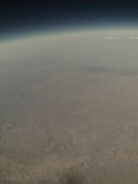
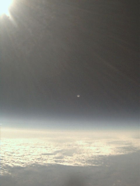
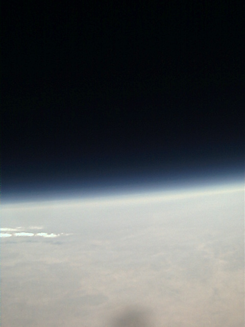
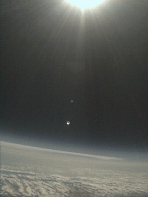
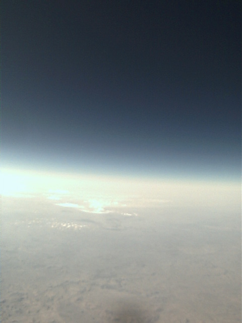
We managed to collect a lot of data and downloaded two pictures. See these pictures below:-
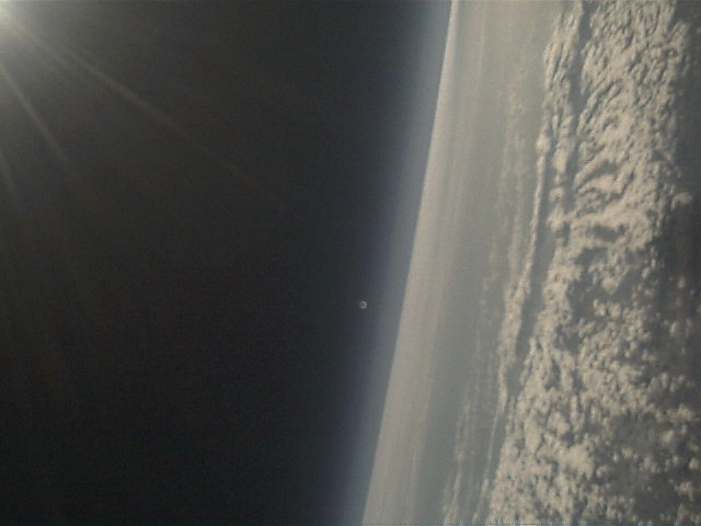
First one is at approx 5000m, the second is at approx 23,000m. Notice the moon in the second photo?
We aim to hike out to the landing spot next weekend and recover the payload.
(More info on successful launch later…)
We have had a NOTAM created, so we have completed all steps to ensure we comply with the launch.
For those interested, the NOTAM is:-
GG YSCBNOFE
300144 YBBBZEZX
C1584/14 NOTAMN
Q) YBBB/QWLLW/IV/M/W/000/999/
A) YBBB
B) 1410312000 C) 1411070700
E) UNMANNED BALLOON LAUNCH WILL TAKE PLACE BRG 151 MAG 16NM FM CHILLAGOE (YCGO) AD PSN S17 22.8 E144 39.8
F) SFC G) UNL
Even as we draw closer to the launch date, we are continually making refinements to the launch procedures and devices to mitigate possible risks. Some of the risks have been identified and listed below:-
We have addressed (1) by contacting BOC and asking if we can take a spare cylinder. We can, and we are able to return it for a Credit if not used. (Thanks Cairns BOC! Really appreciate this).
We have addressed (2) by purchasing spare tubing and superglue so we can manufacture another one.
We have addressed (3) by providing another button on the web interface which the operator can use to disable picture downloads.
We are putting a bit more thought into how the day will progress. The exact details of how the launch will be conducted are still something that will evolve over time and become clearer once we have a predicted flight plan. Like any problem, we are going to split the flight into several stages. Most likely something like this:-
| FROM (Min) | TO (Min) | Notes |
| 0 | 15 | Observing – seeing how close to predicted path and speed, etc. Will then confirm path. |
| 15 | 35 | Driving approx 30km (or distance determined) |
| 35 | 55 | Observing – get gps co-ordinates + photo (if can) + health status |
| 55 | 75 | Driving approx 20km |
| 75 | 85 | Observing…till balloon pops (Should be approx 83rd minute) – Will first disable photos. |
| 85 | 100 | Driving approx 15km |
| 100 | 111 | Observing decent till out of range. (flight length approx 1hr 51mins). |
We have released software used to manage the flight. It is downloadable from GITHUB:-
Software for the groundstation (runs on Beaglebone Black running Debian)
https://github.com/joeman155/JJTEAM_GS.git
Software for Arduino
https://github.com/joeman155/JJTEAM_HAB.git
X-modem library required by JJTEAM_HAB
https://github.com/joeman155/JJTEAM_XMODEM.git
There was much thought and time spent trying to find a suitable design/construction procedure for a radar reflector. There are several ones on the Internet, e.g. Instructables one, but they did not seem that practical/suitable. This post describes how our Radar Reflector was built.
The requirements of a reflector are:-
For materials I decided to use core-flute material (Sold at companies that create signs) and Aluminium tape (50mm x 5metre) from Jaycar and two cable ties.
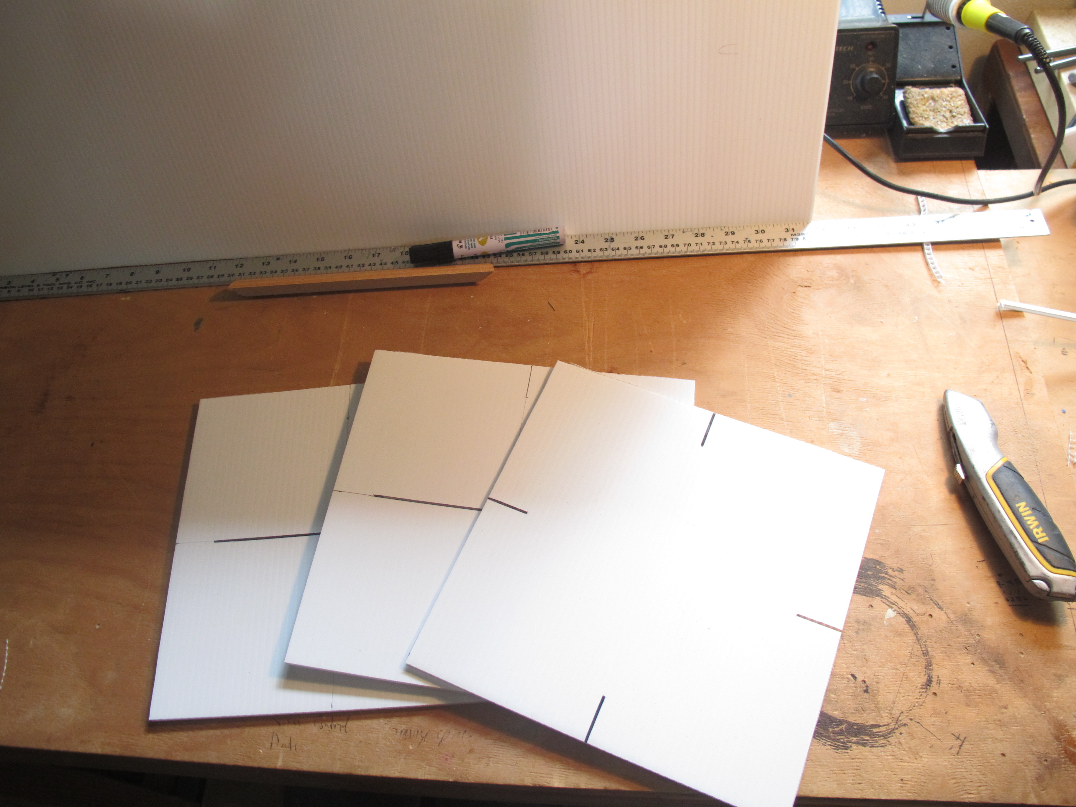
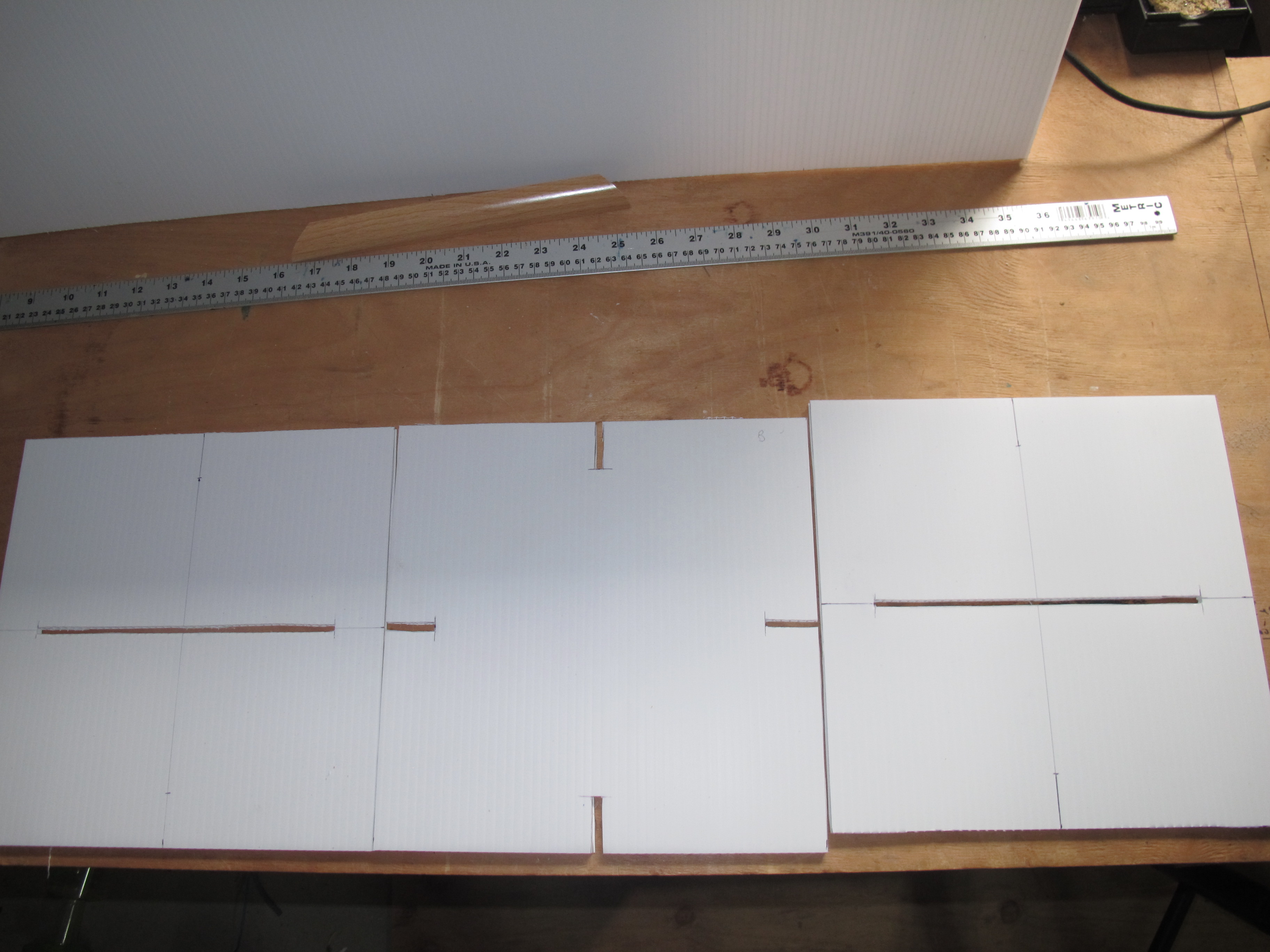
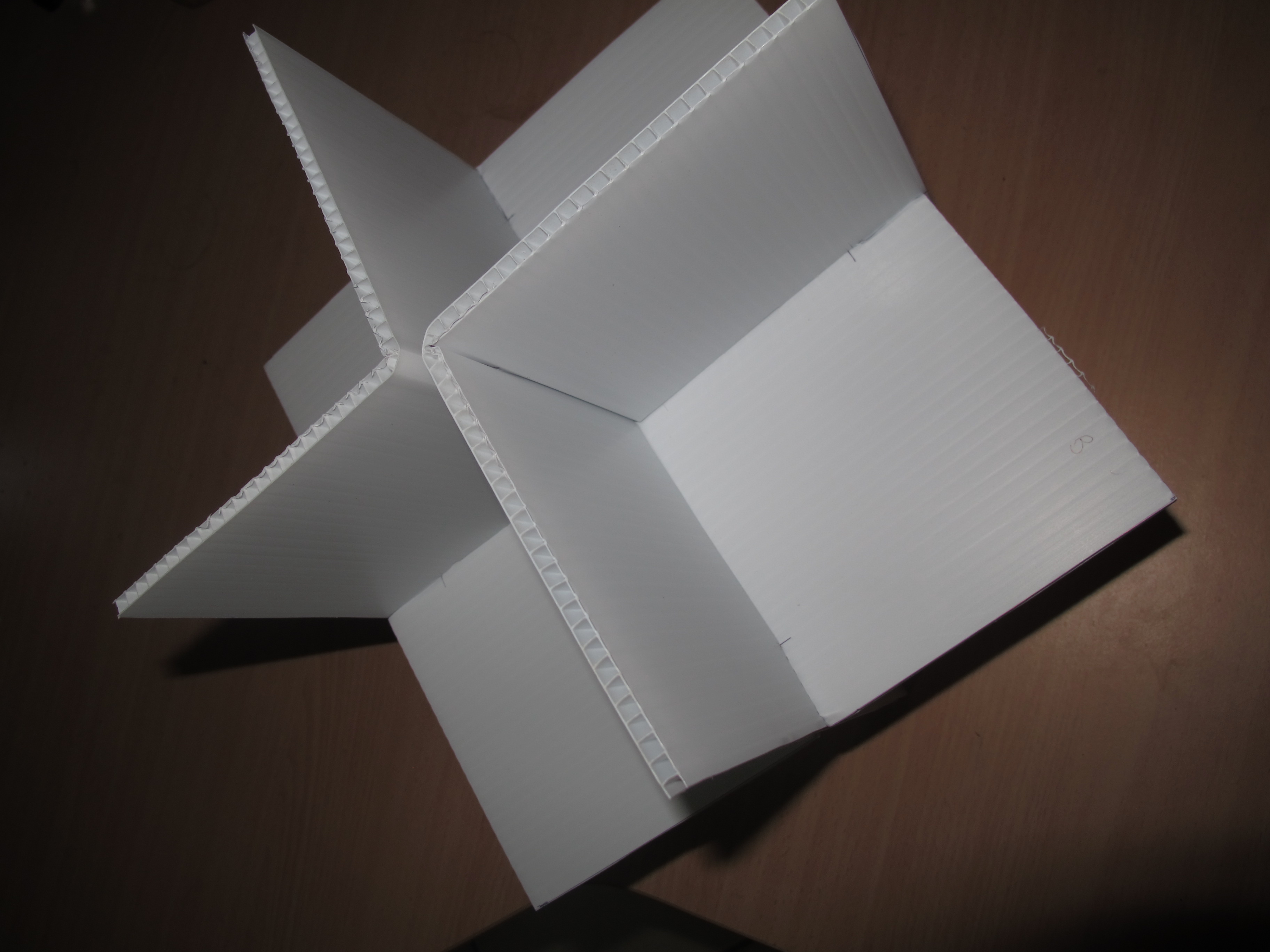
The construction is best illustrated I think using some photos. Please see below:-
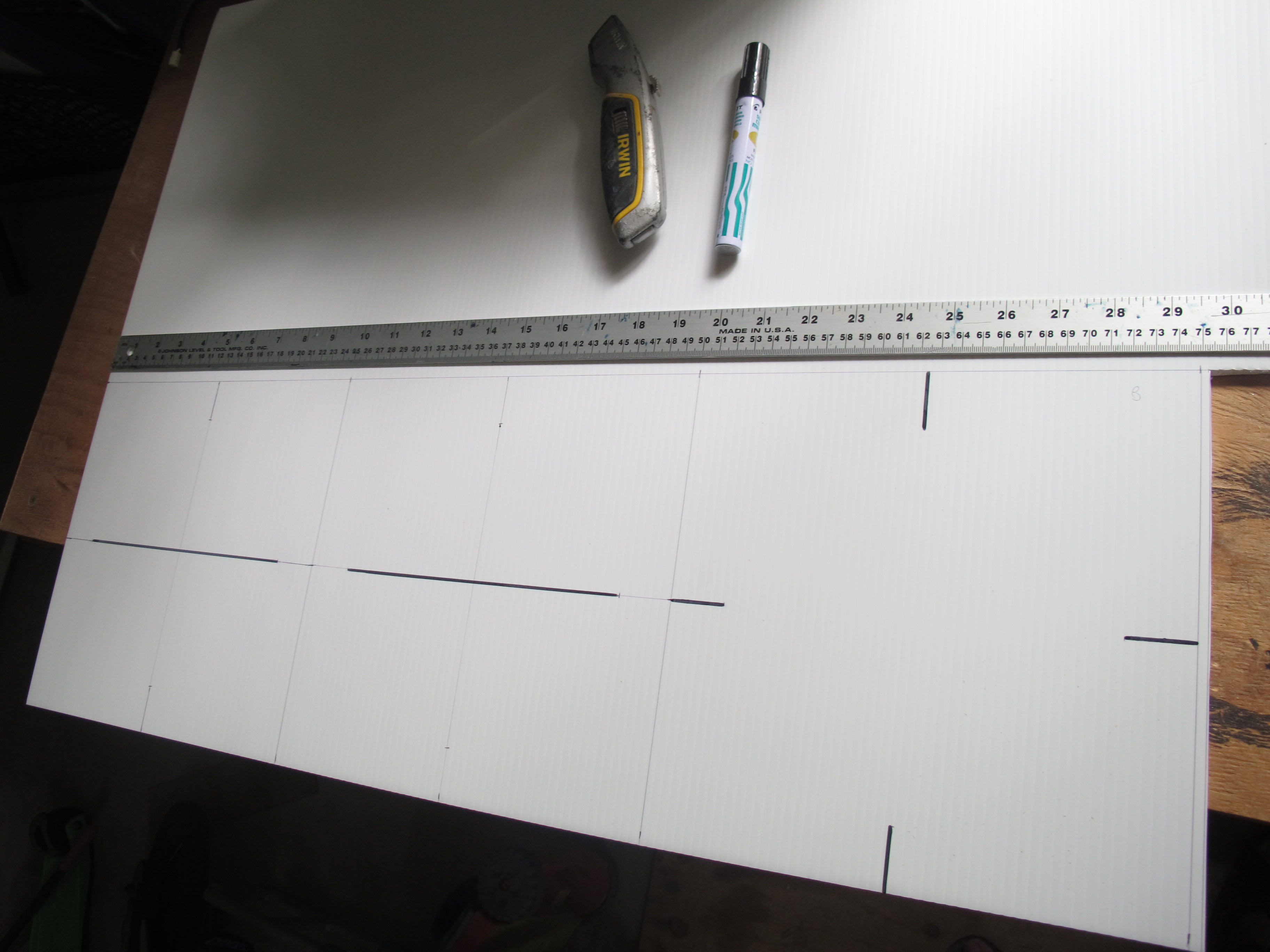

We will drill a hole later on in a corner for the thread. Will re-enforce this hole with additional Aluminium tape.
It became obvious that there are probably some ways to make the build process a lot easier. Possibly putting tape on initially before cutting and putting together.
I do also wonder if we “really” need to have Aluminium tape on both sides of the Coreflute; but decided in the end to apply it to both anyhow.
But it is strong/rigid, light, not too difficult to make and inexpensive.
The Balloon can in some cases travel quite far distances and so tracking the balloon needs to be as easy as possible. Much useful data, like GPS co-ordinates, speed and direction are already gathered. We also calculate and display the distance between the ground station and the payload. A graphical representation of the trek of the balloon and the position of the groundstation – a map – would be most helpful. This post describes the steps to accomplish this.
OpenStreetMap (http://wiki.openstreetmap.org/wiki/OpenStreetView) is a very good “free” mapping software that can be installed on a LINUX based system. First we needed to assess this piece of software and its suitability. It was initially installed on a Debian machine using a map that encompasses a fairly large area of the Cairns region, where all balloon trajectories are within. Initial testing suggested it should meet the requirements – it was highly functional and showed the main roads that would be traveled and the API DEV interface is well documented.
The installation process was replicated on a Beaglebone Black. Angstrom Linux was ditched in favour of Debian Linux. Additional space was required, so an 8GB microSD was inserted, formatted and mounted. I had to go through the whole slow process of compiling support for the RTC_DS3232 module and get wireless etc going. Because a lot of additional packages were required, many unrequired packages had to be removed.
The result, a map that can be viewed offline and show all the waypoints of the balloon and the position of the groundstation when using a phone/pad device with built-in GPS. Below is a screenshot of it.
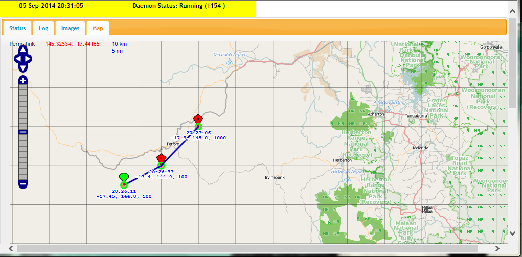
Here is an example with predicted flight path in red.
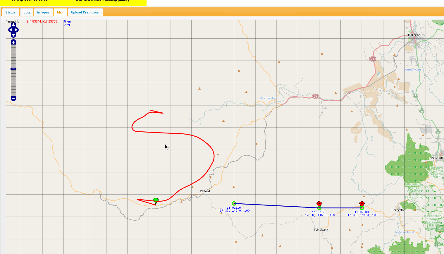
The interface has been written to show only way points for the current day. Red way points are for the balloon, except for the Green one which is the beginning one. A Blue point indicates the vehicle (when we have a GPS enabled device, e.g. an iPhone). Red path is the predicted flight path and can be generated by uploading a CSV file created on http://habhub.org/predict.
NOTE: We don’t have the blue icon here because this was done from a browser without a GPS device.
A line separates each balloon way-point and time/position are recorded against each way-point.
It can be a little slow at times, but when a map is generated and cached, when it is later recalled, things work relatively quickly. Definitely suitable for what we need it to do.
It has been a while since the last post, so I thought it would be a good idea to provide an update in the progress of the project.
Since the project has changed quite a bit, I’ve decided to do up a short video of the payload systems. Please find below.