I’ve progressively refined the design of an engine block. This is a device that sits inside the air-frame, about 1/2 way along the air-frame, either glued or screwed in. To it we have a hook for the shock cord and a the bottom we have a point to screw in the motor using Aeropack adapter.
Design 1
The initial design was using a 30mm Aluminum tube section with Aluminum ends and an eye bolt.
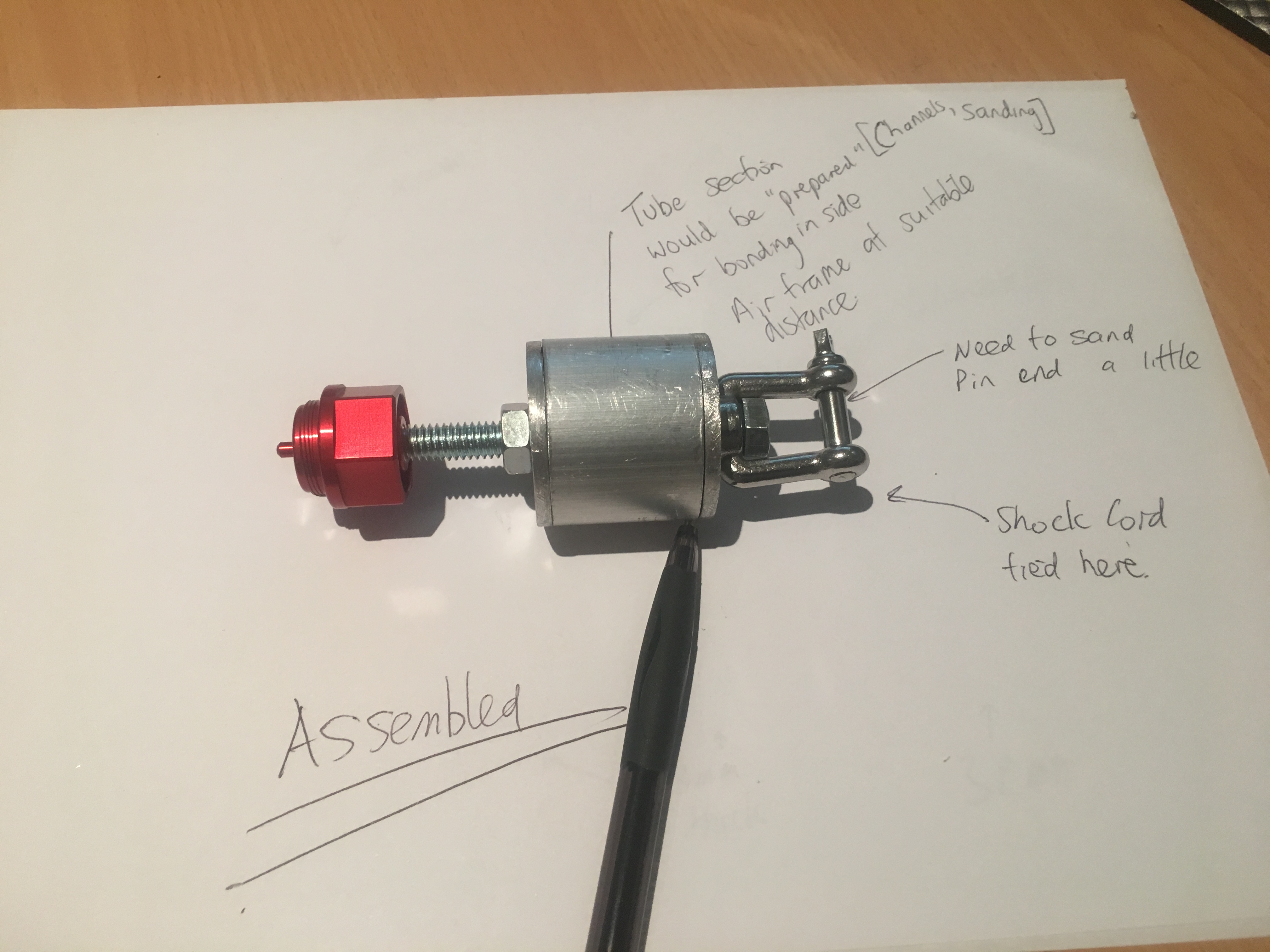
Design 2
This then morphed into a 40mm 3-d printed tube section with Aluminum ends with small shackles.
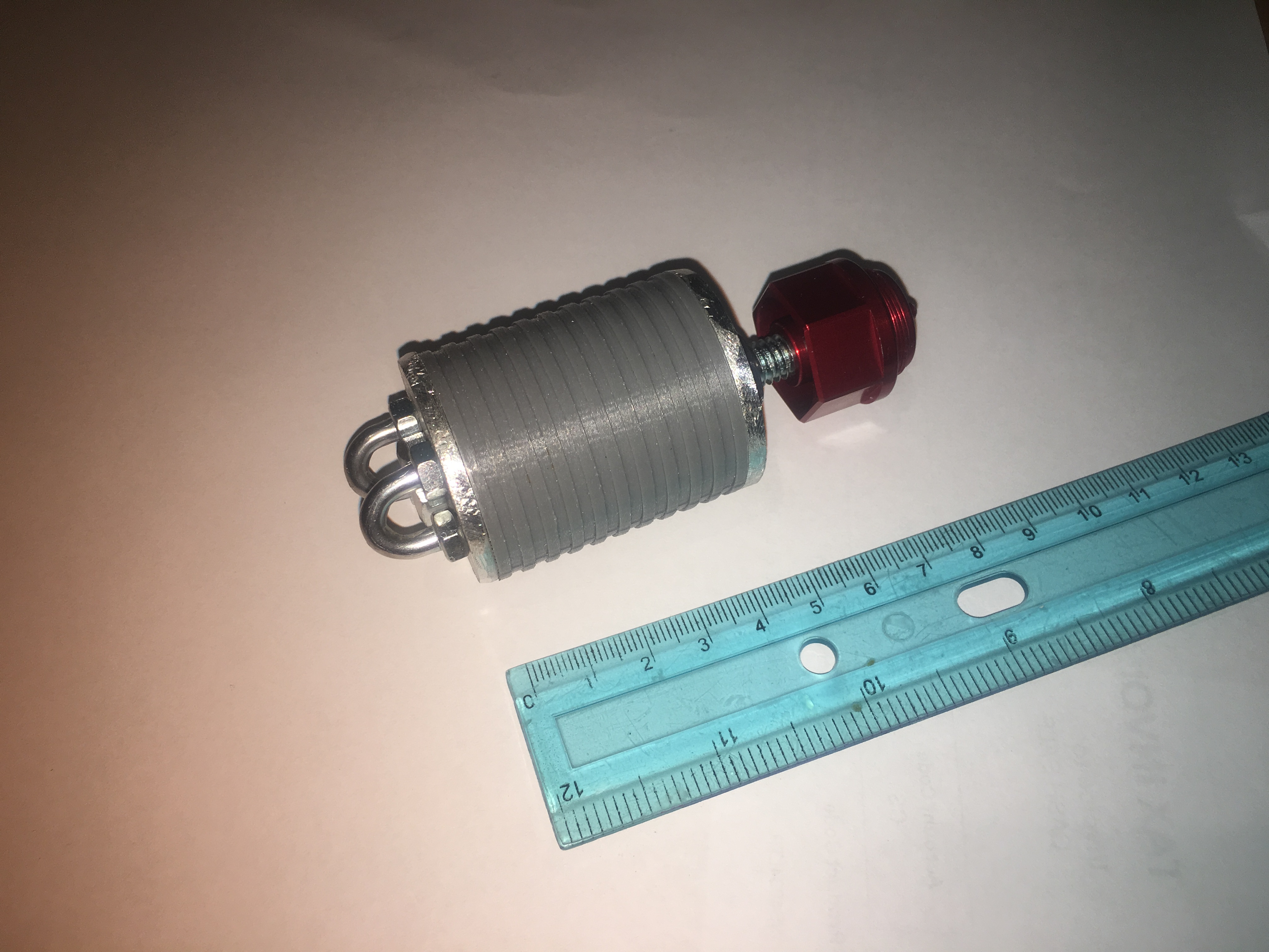
Design 3
This then morphed into a 20mm 3-d printed tube with G-10 ends and a bolt with a welded nut.
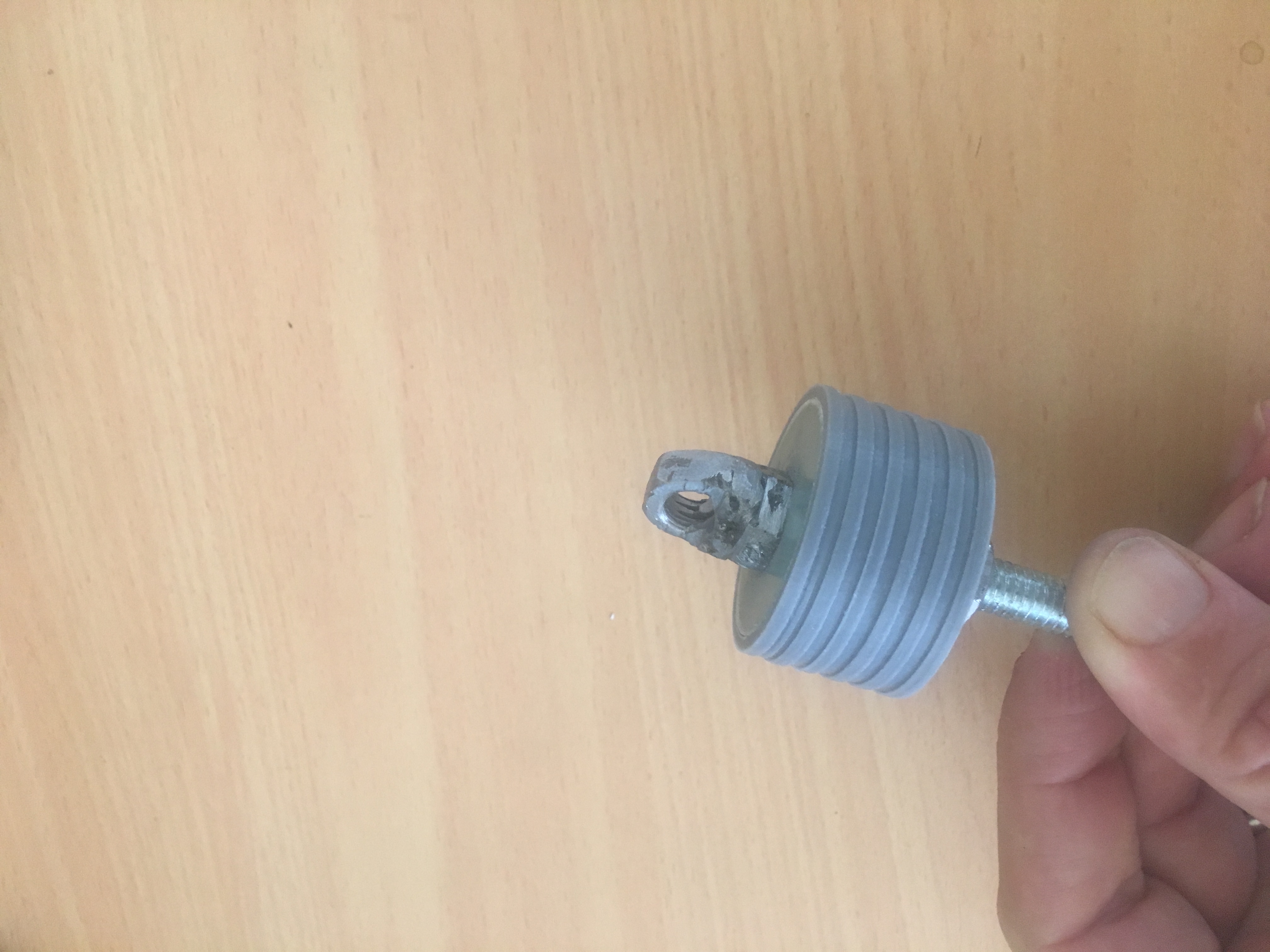
Design 4
This then morphed into a 20mm 3-d printed tube with G10 material ends with much smaller bolt, with the one of the ends recessed 10mm from one end and a 3/16″ eye bolt screwed INTO the main bolt. Take note of the “channels” in the exterior of the block.
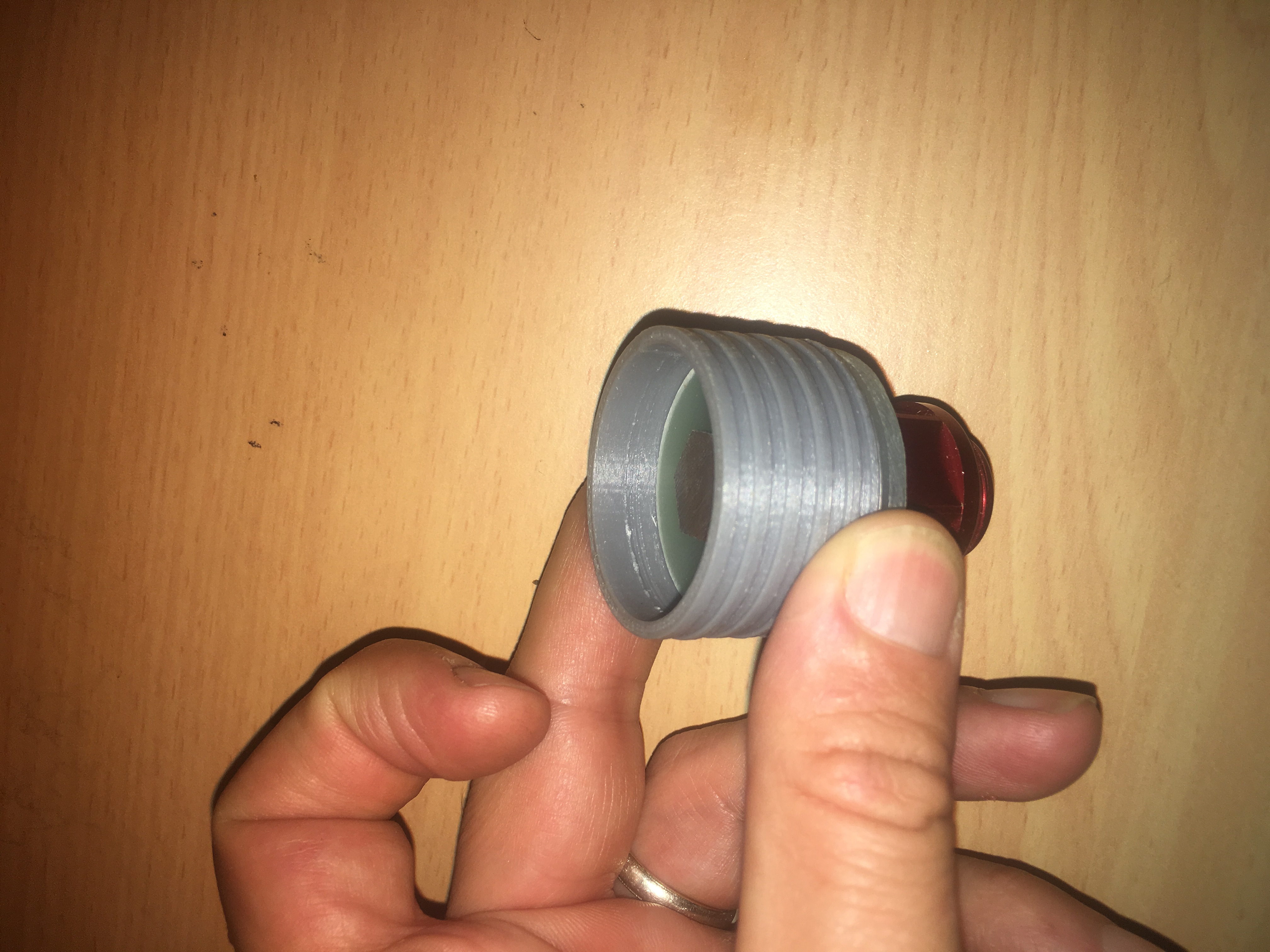
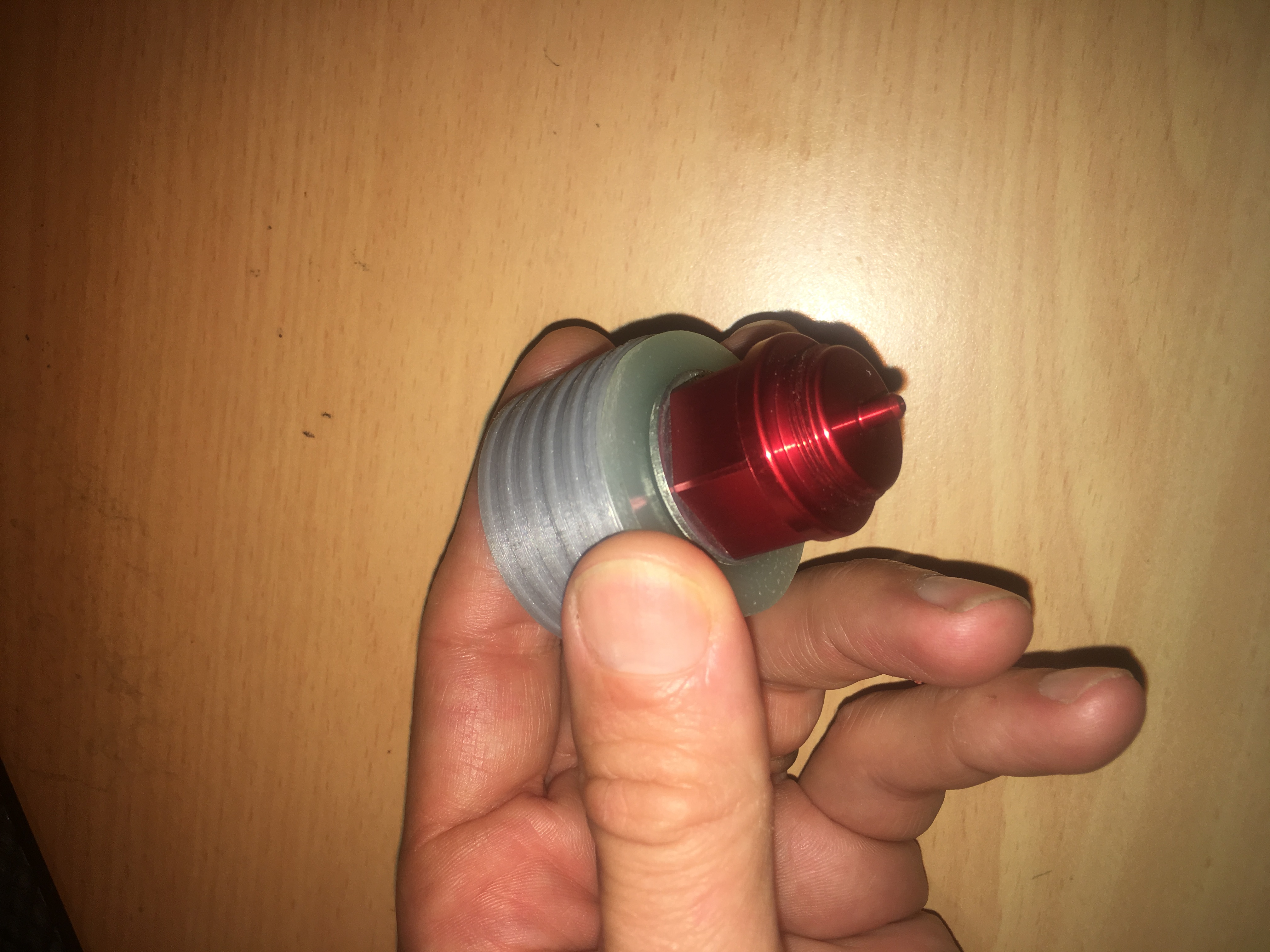
The last one can easily take 20kg load using the “hammer” test in BOTH directions.
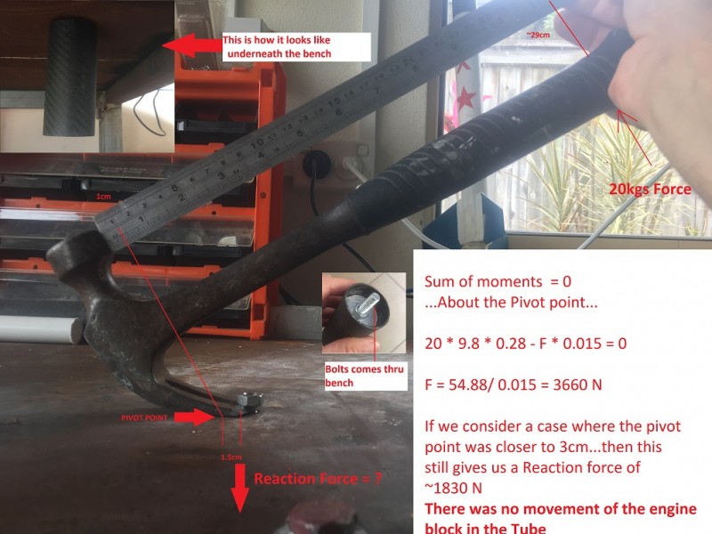
On the final version, I was able to exert 20kg loads in either direction without failure. Failure being movement of the Engine block. i.e. this design is adequate for the task.
Expected Loads
The thrust of the motor is expected to get up to ~800N in the UP direction. The force of the ejection gases is expected to be about 300N. i.e. considerably less. Remember, we are unlikely to use shear pins in the retention of the upper segment of the air-frame. Instead, we will use strategically placed tape to provide interference fit that requires certain level of force to overcome.
How it was glued in
I marked distance down the air-frame where I would glue the Engine block. This was to be sufficiently far in so I could install a 6GXL motor case in the future, if I desired.
Next I sanded the internal surface with GRIT-60 sand paper on a stick and then I cleaned it with a damp rag.
Gluing it in was not a simple task. I had to apply glue to:-
- The block itself, in the external channels using a blade to ensure there was minimal excess
- The inside of the airframe.
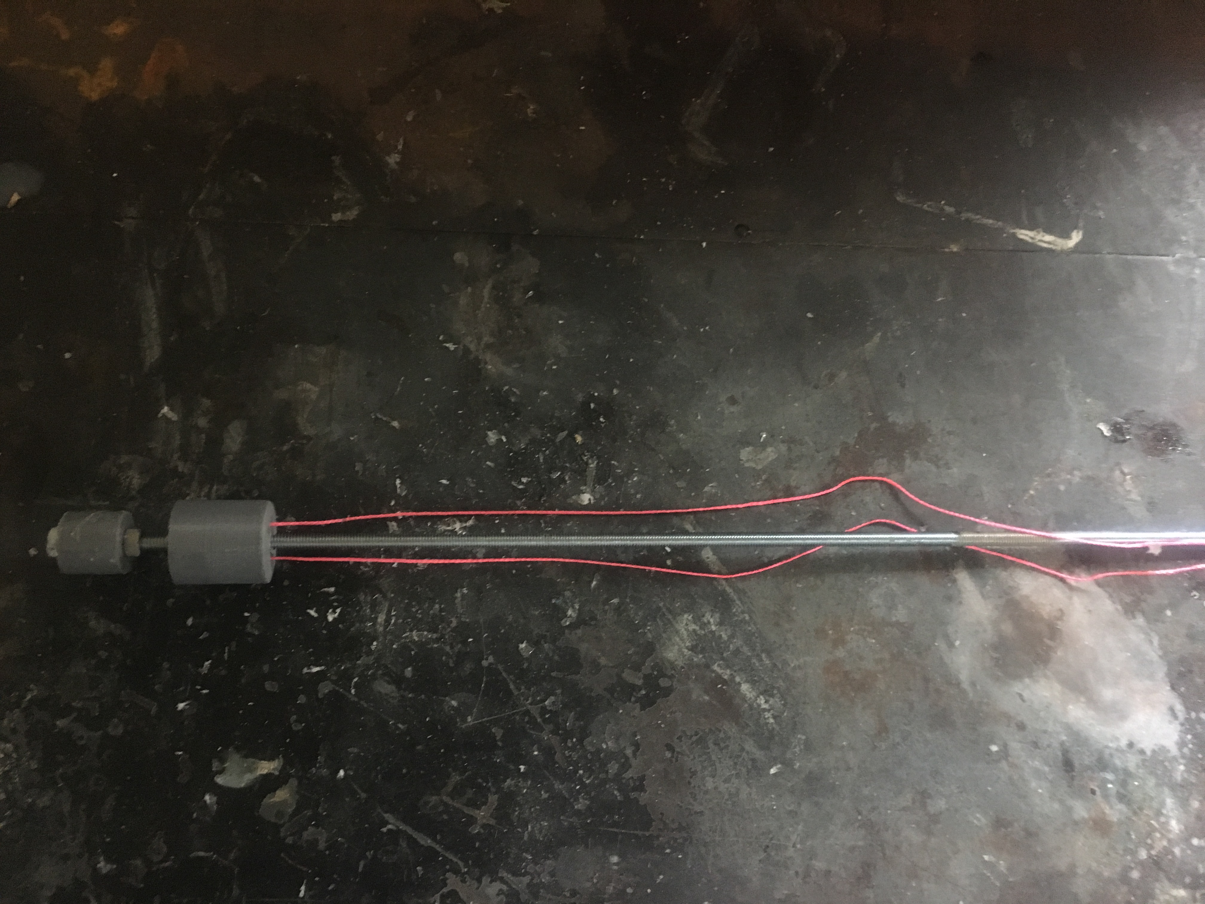
I wanted so smear enough epoxy in the RIGHT place in the air-frame. I created a contraption that I would guide along a 5/16″ rod to the correct distance along the air-frame and then I would let it touch the inside of the air-frame as I rotated the air-frame.
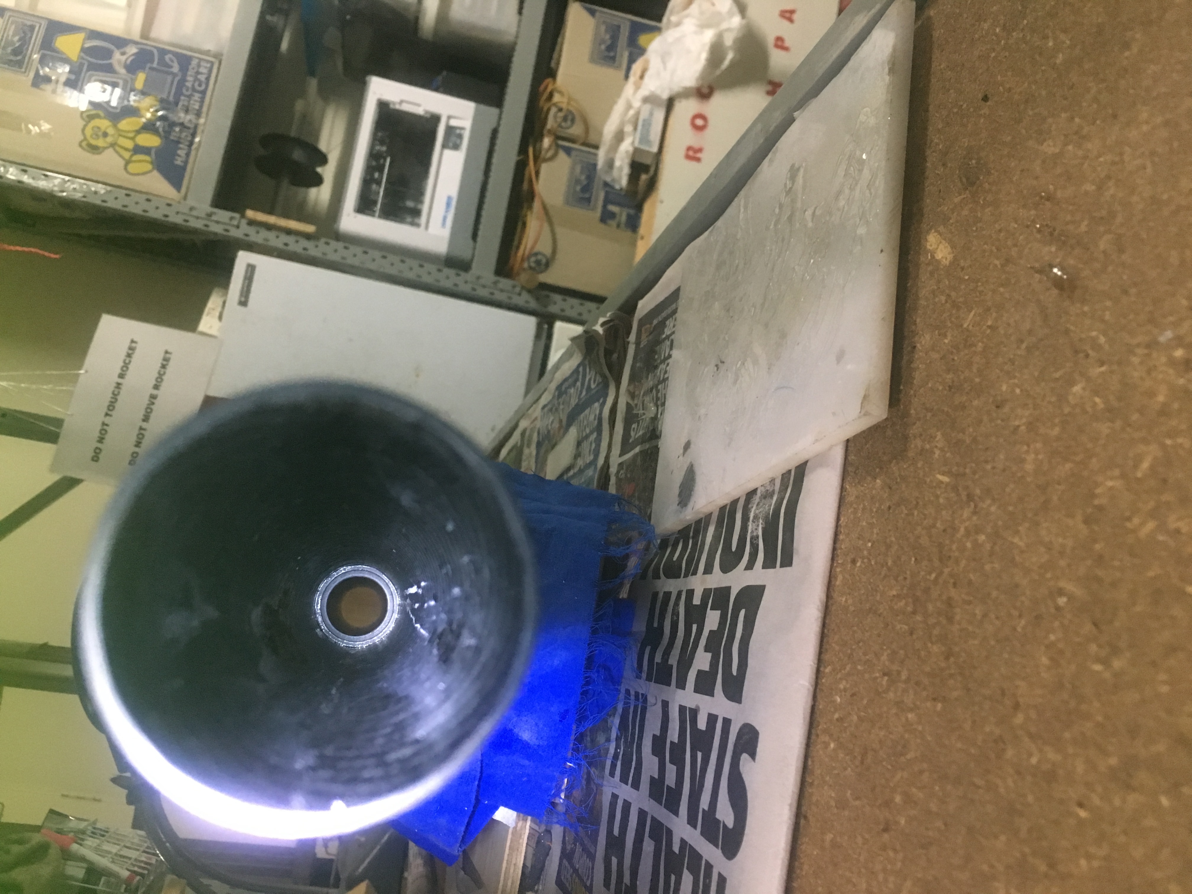
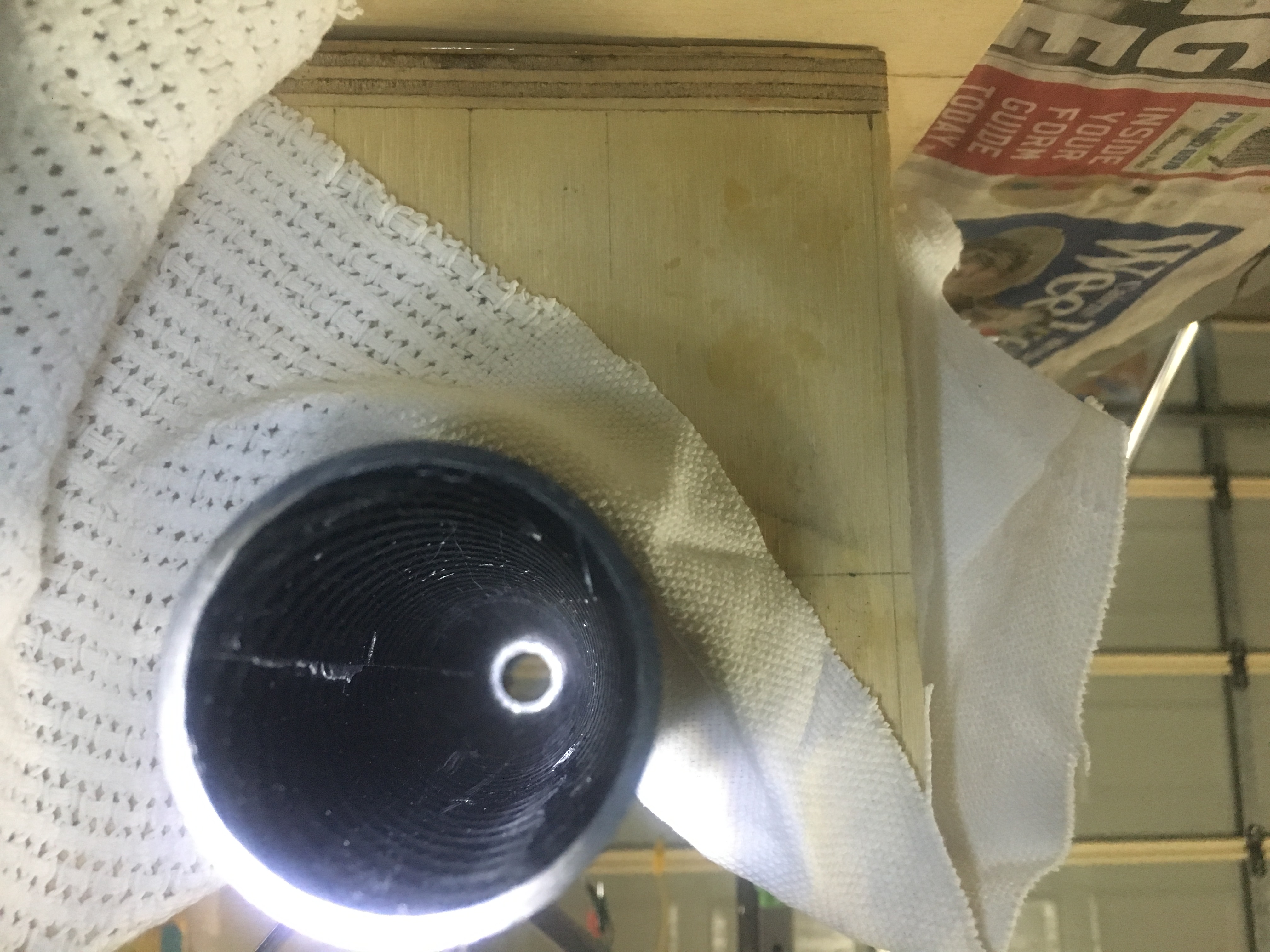
How to assemble it
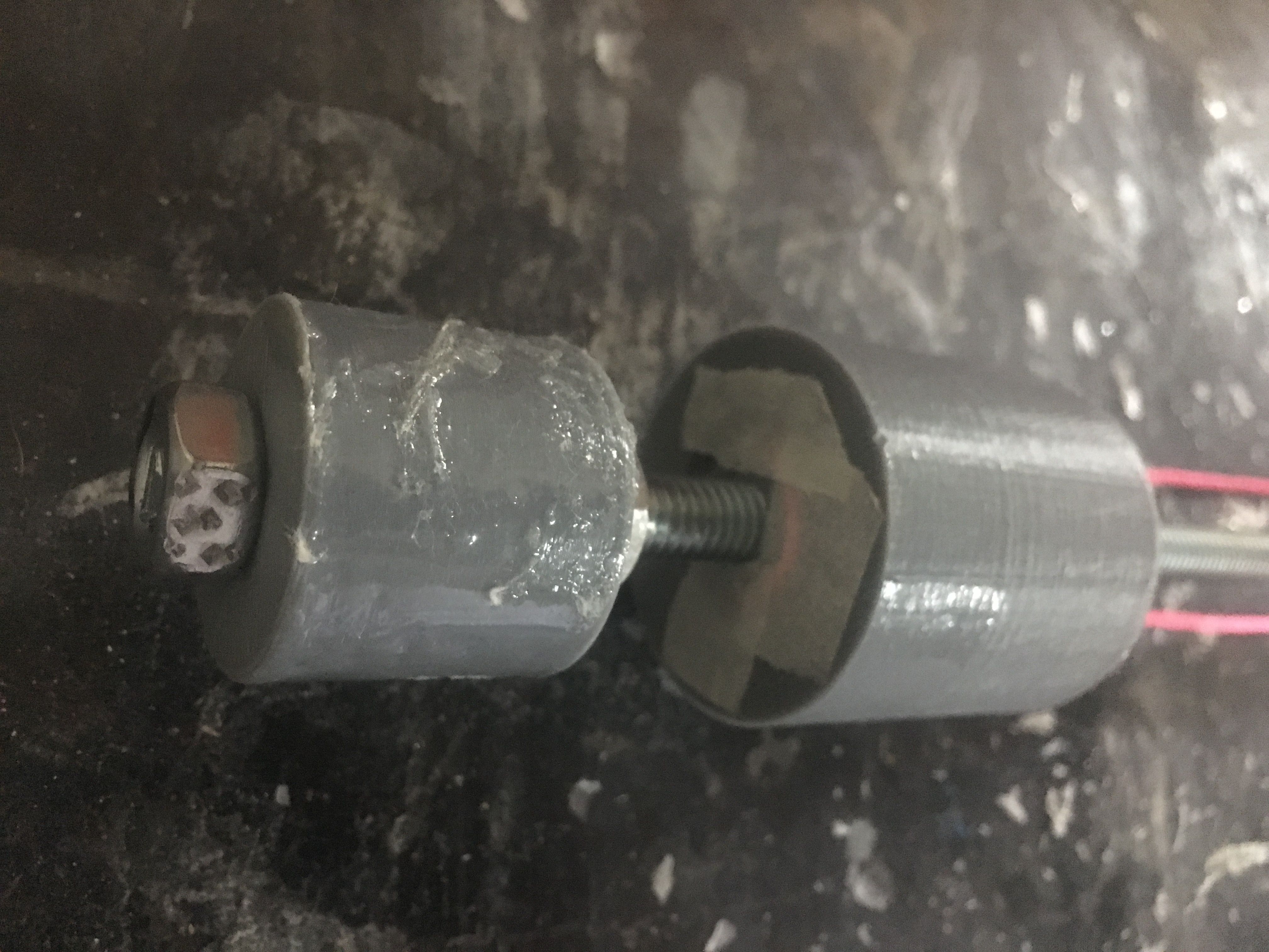
It is difficult to assemble without some special tools. Below are some photos of some tools I created to get access to the parts.
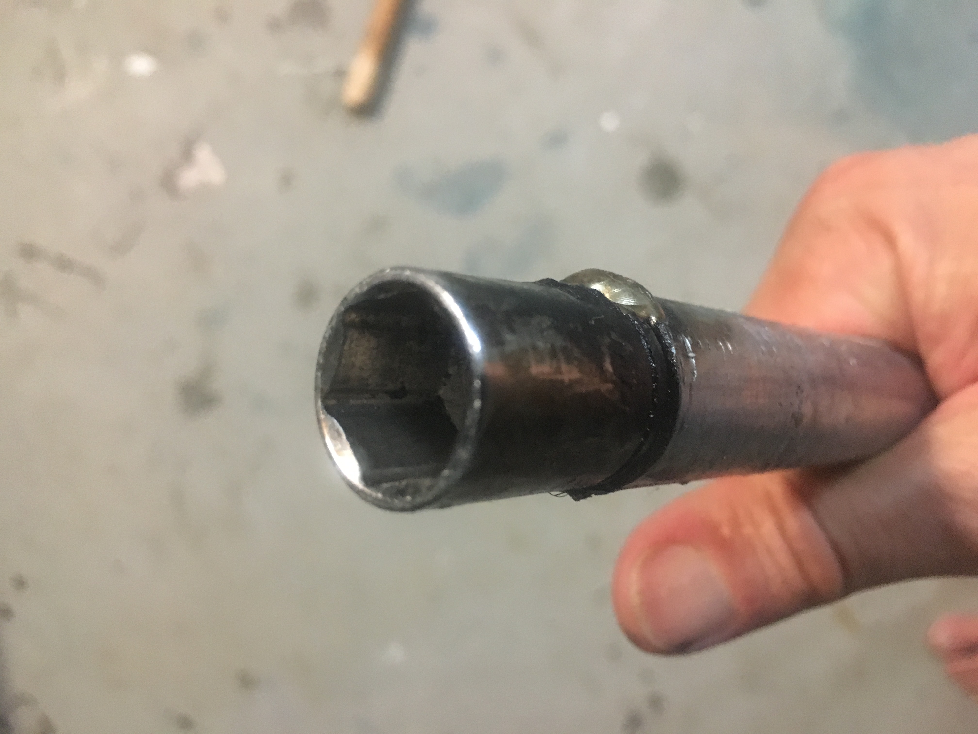
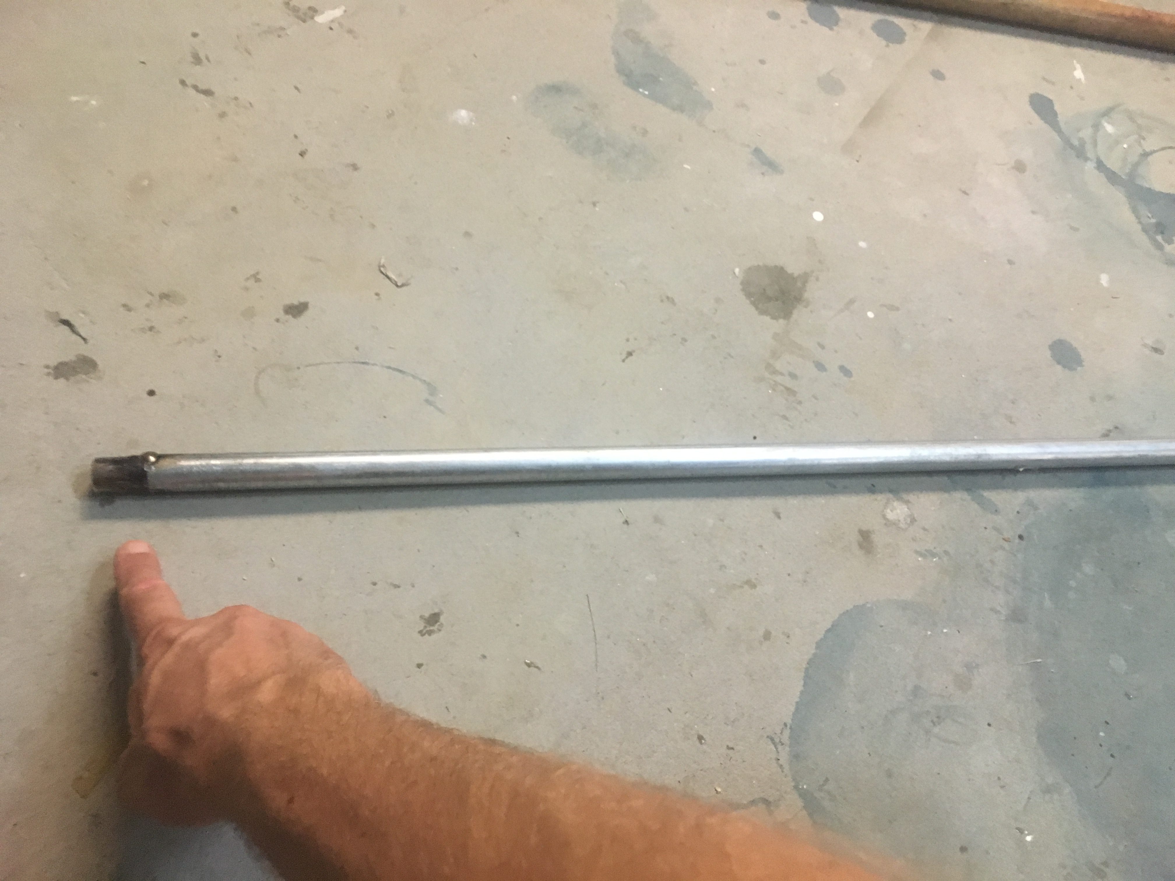
I had to weld a socket onto the end of a large steel tube. The tube was sufficiently large so that the bolt could easily go into the pipe, so I could be sure to completely tighten the nut onto the bolt.
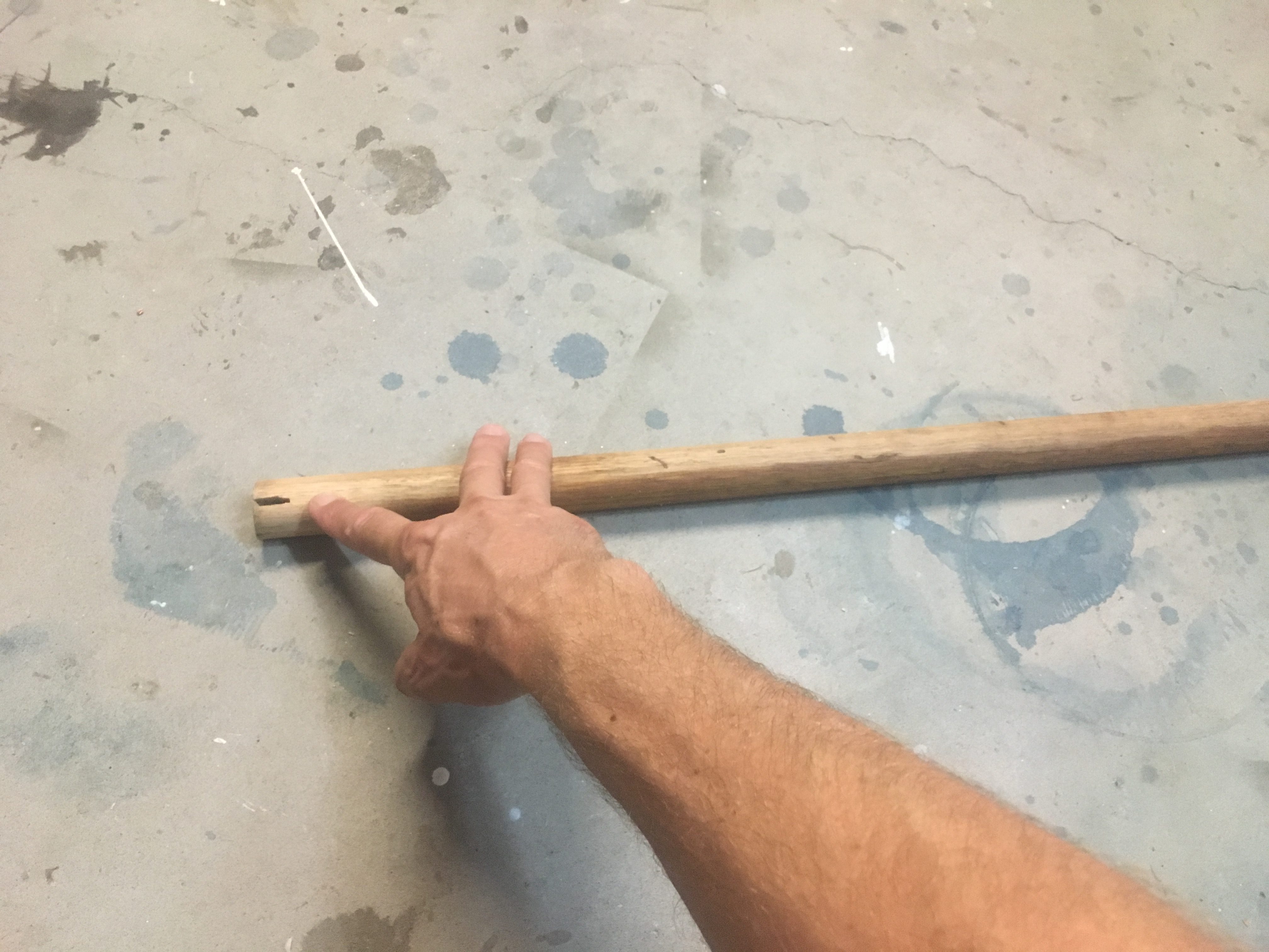
The other device was a solid piece of dowel in which I cut a slice into it, so I could friction-fit the it over the eye-let bolt.
