Gluing Motor Mount inside Airframe

I have checked the steps many times over several days, trying to make very sure I have not mis-understood anything, measured anything incorrectly, missed any steps that might be good to do now.

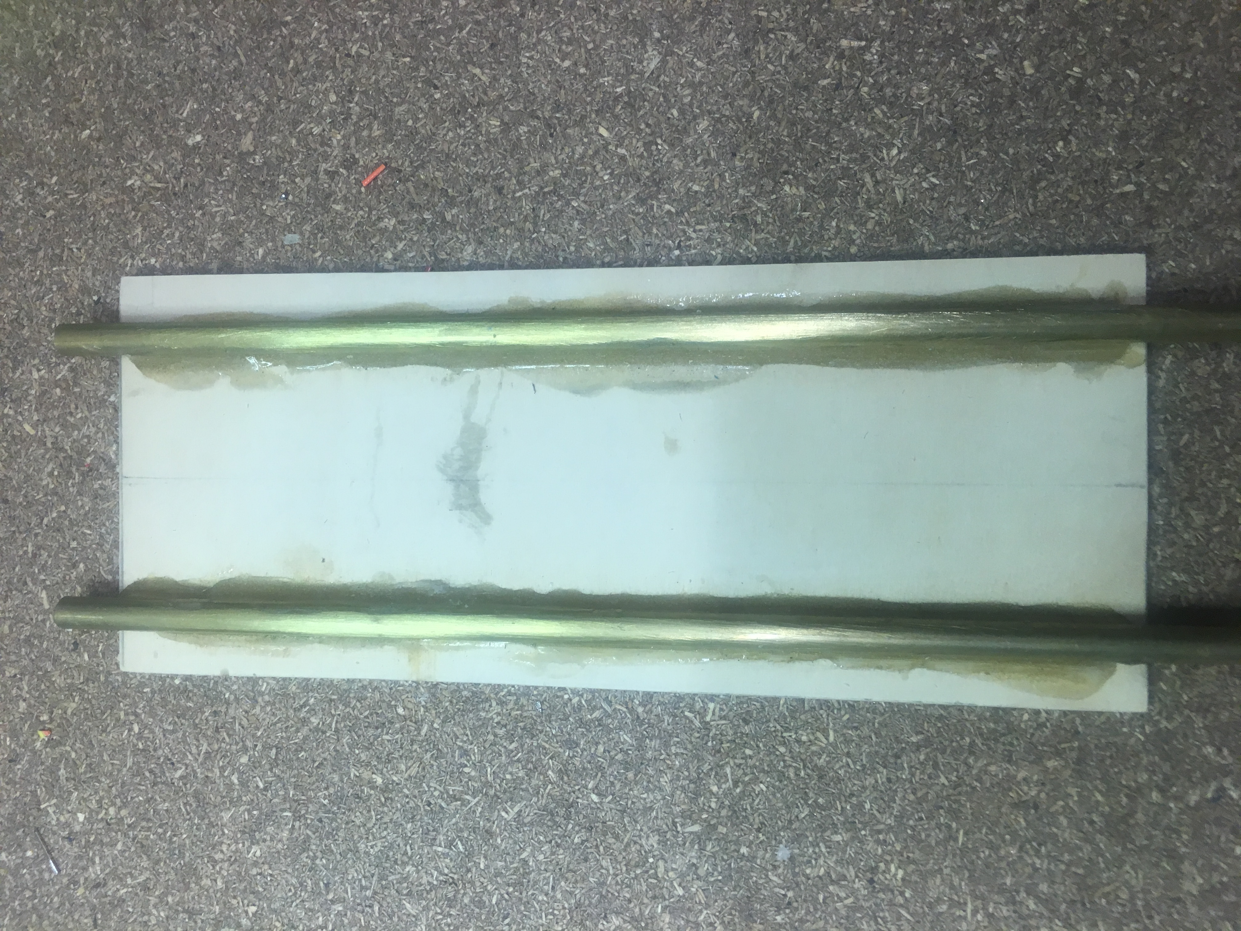
I then performed several dummy (pretend) attempts at gluing the motor mount into the Airframe, to help me anticipate any potential issues and also have the best procedure to glue this motor mount into the Airframe. I was able to confirm that I could see where the glue was in relation to the lines inside the air-frame.


Making a batch of 24hr araldite glue


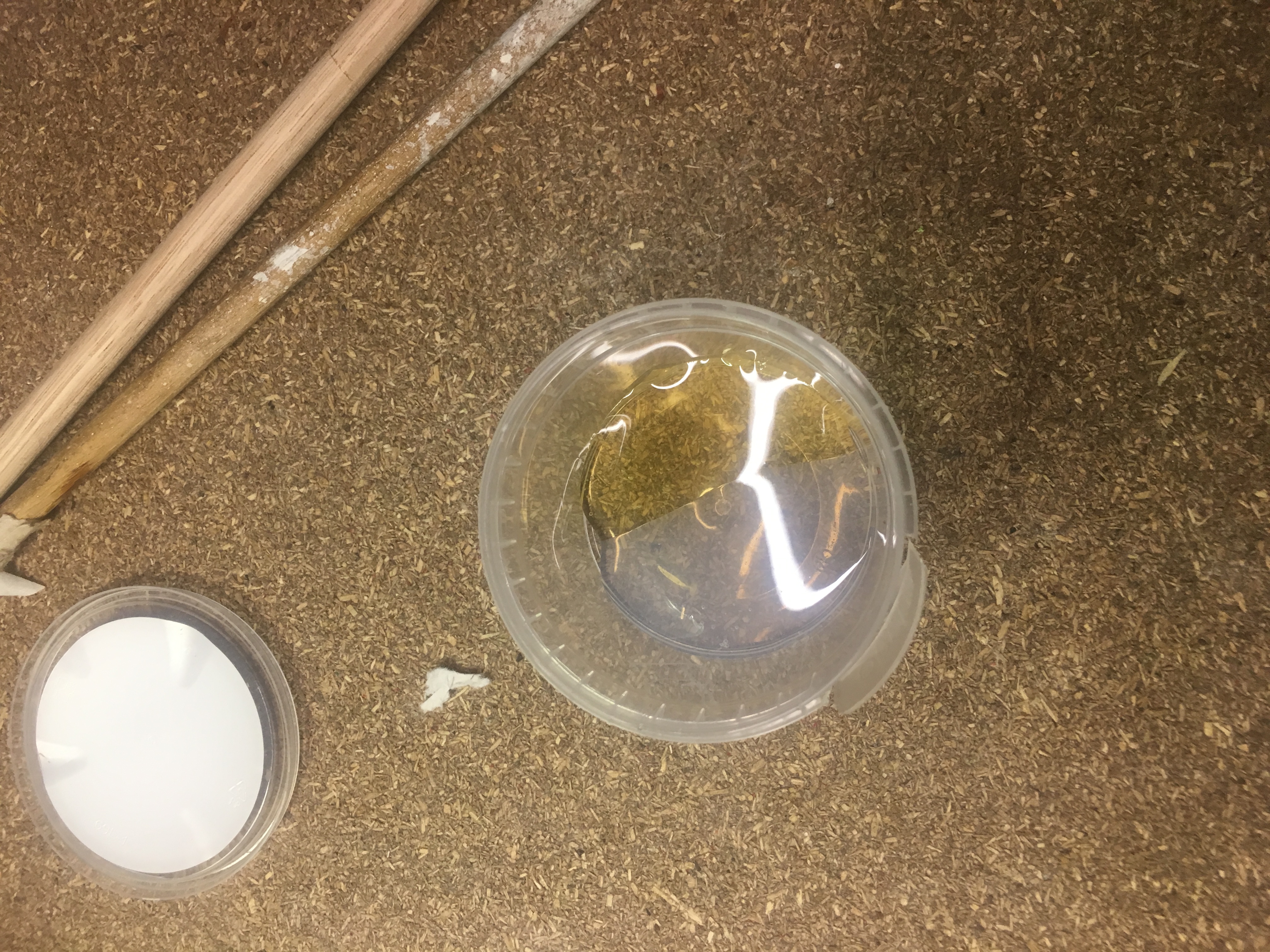
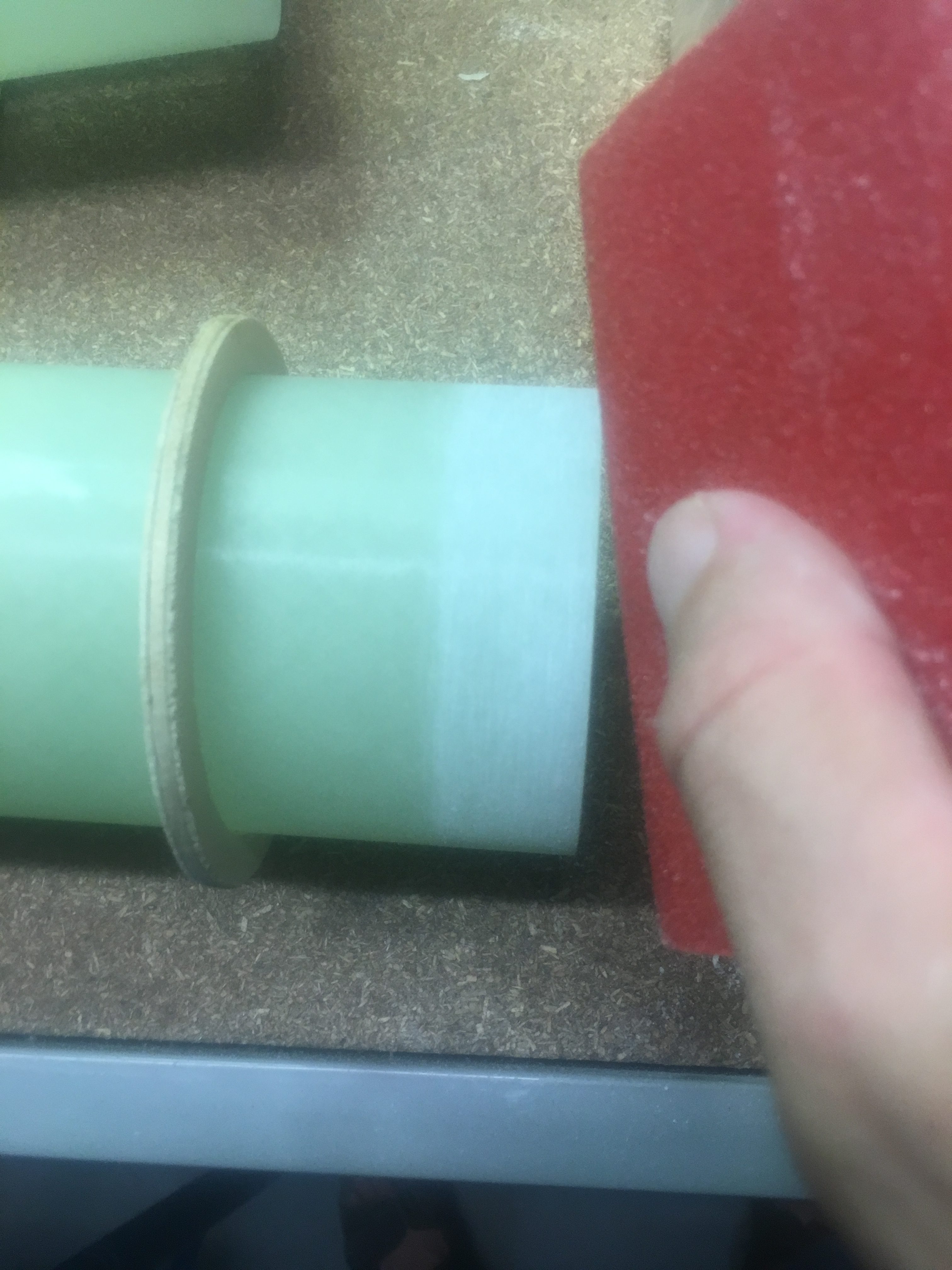
I made two batches of araldite actually. Wanted to make sure I had more than enough glue.

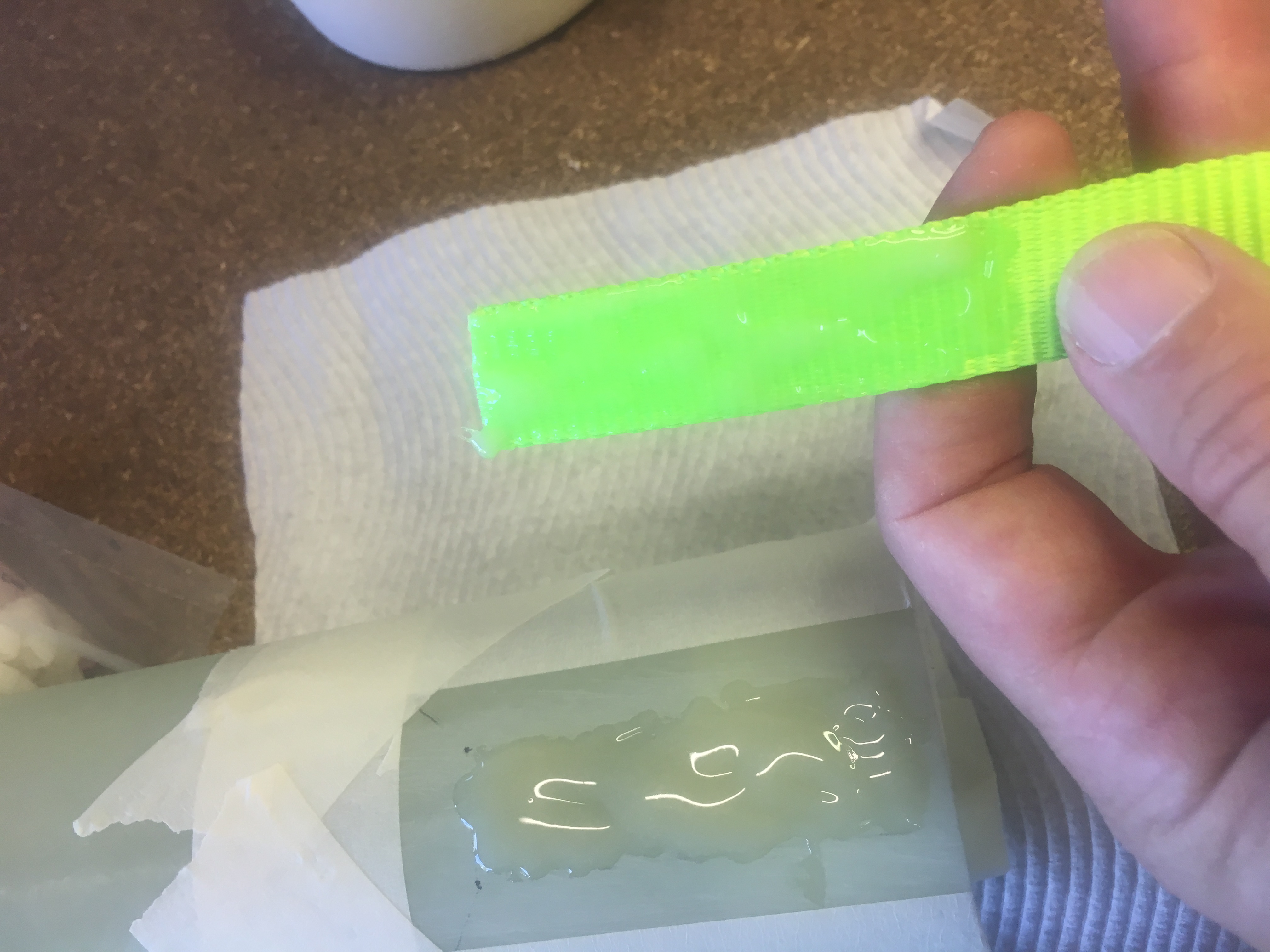
I put glue on the stick end and turned in my hand as I put it down in between the two lines. I used the cut-out in air-frame (for the fins) to ensure I got the glue in the right spot. The occasional motion of the air-frame stopped glue from dripping from the edge and allowed me to paste a nice layer of araldite in the air-frame. Then I loaded the motor mount  and twisted in back and forward to ensure the glue was spread about in between the centering ring and the air-frame.

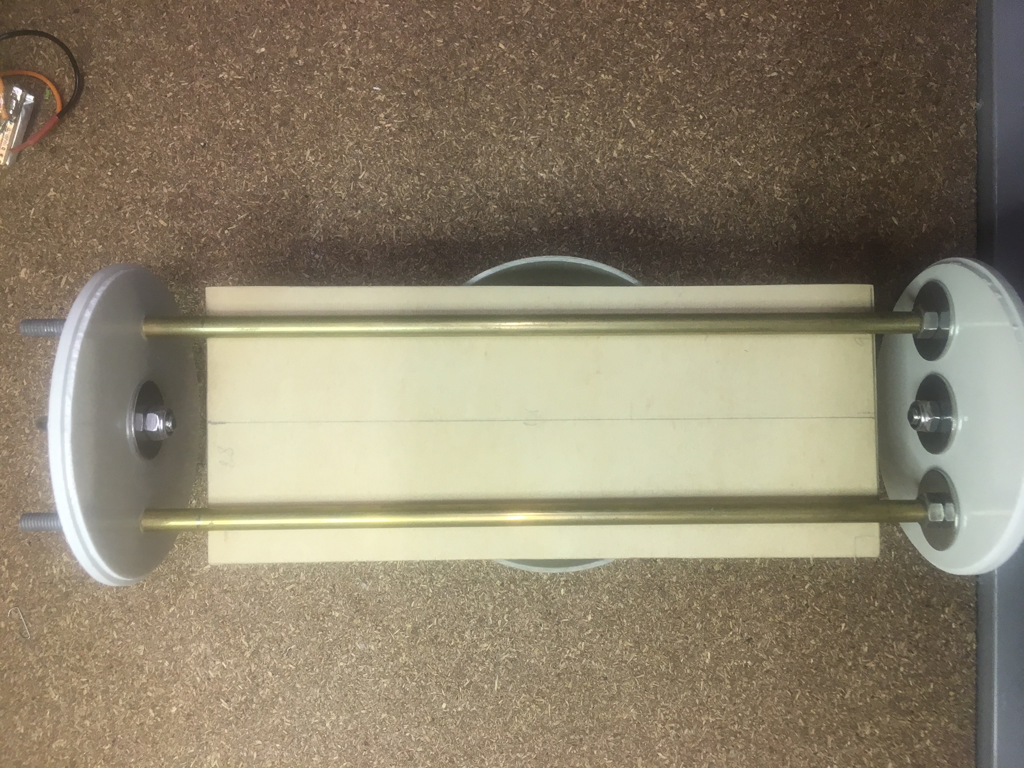
Then I put the whole rocket into the vertical position as shown below:-

Air-frame is cable-tied to the shelving in our garage.

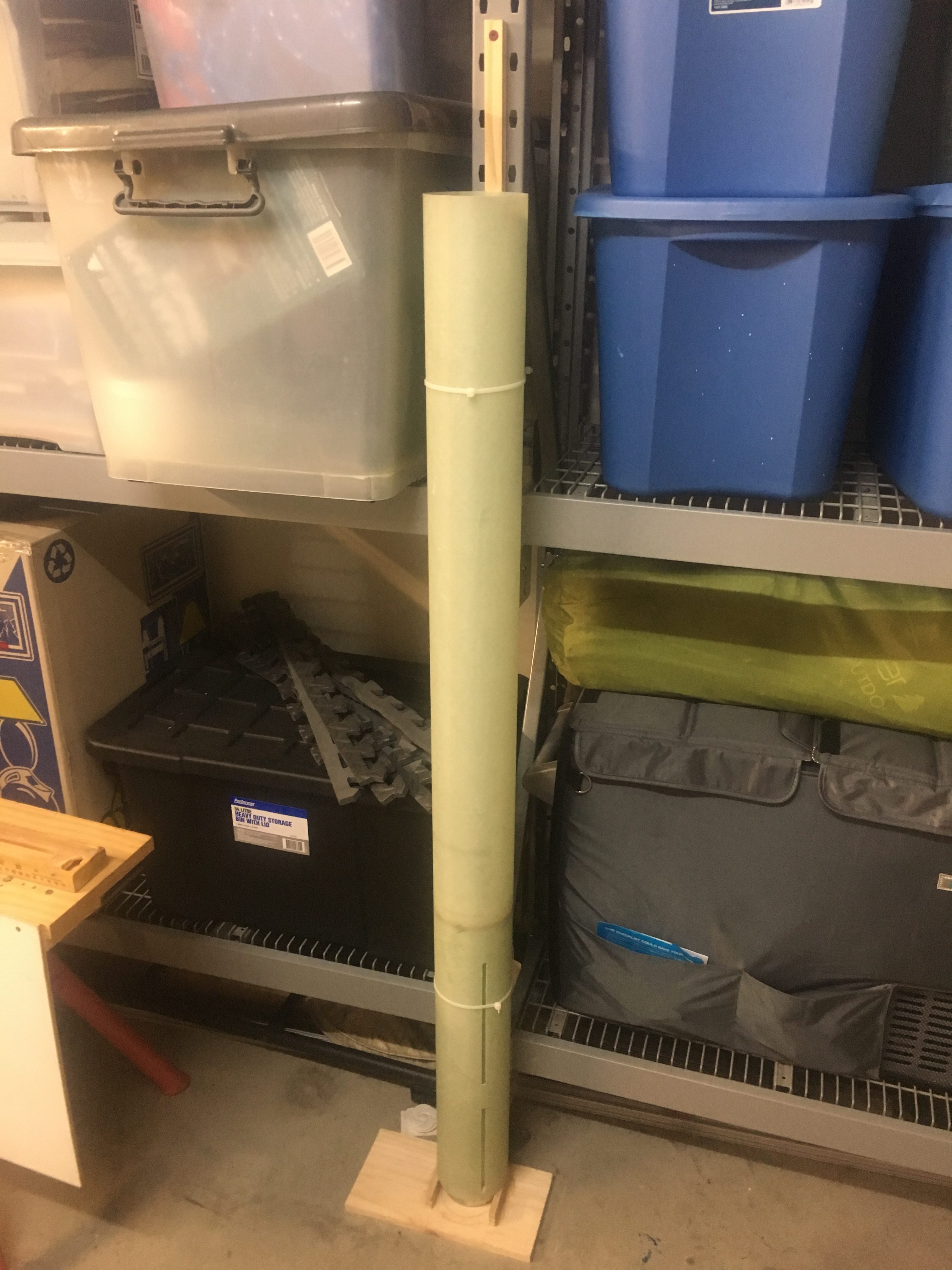
The glue requires 24 to 72 hours to completely cure. So we will give it the complete 72 hours (Sunday 09:30 to Wednesday 09:30). We want the BEST possible result


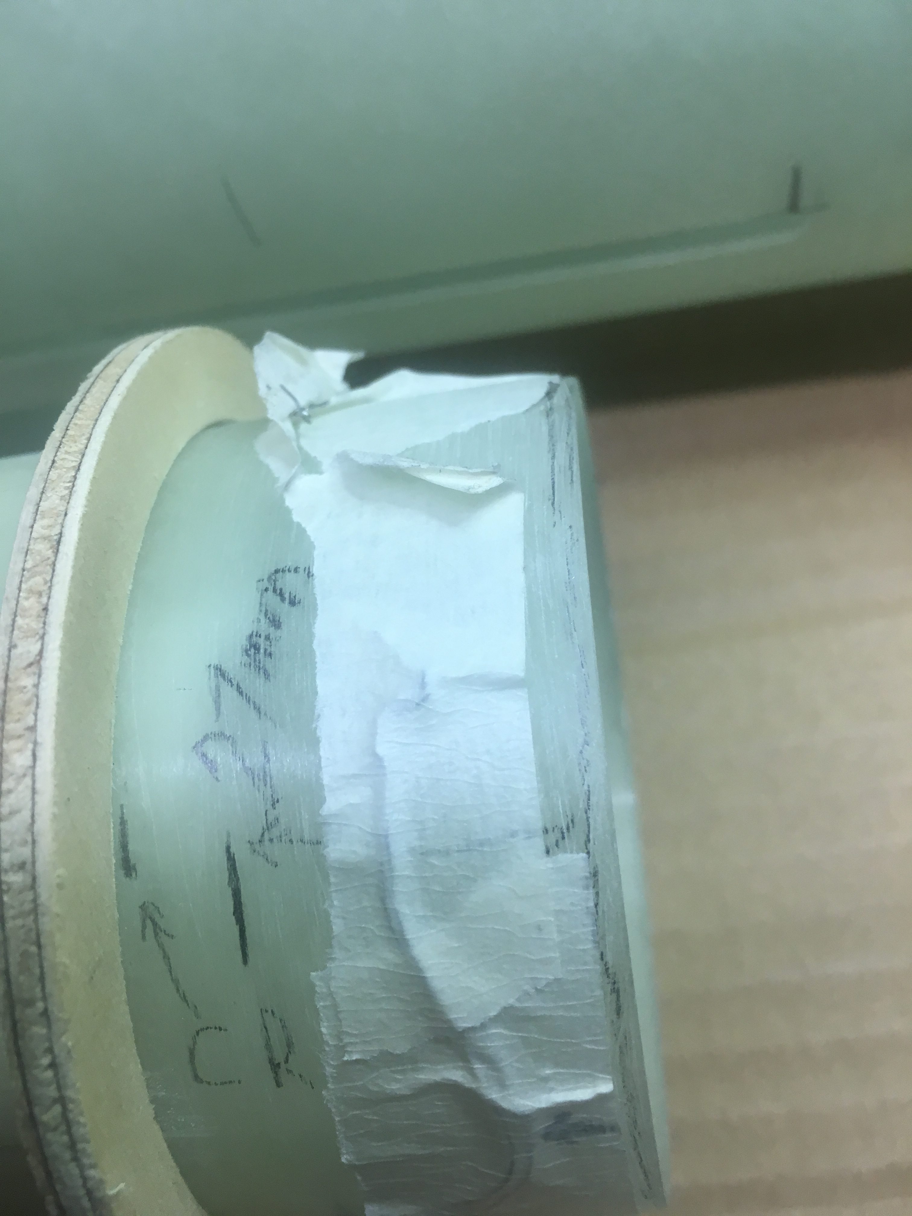
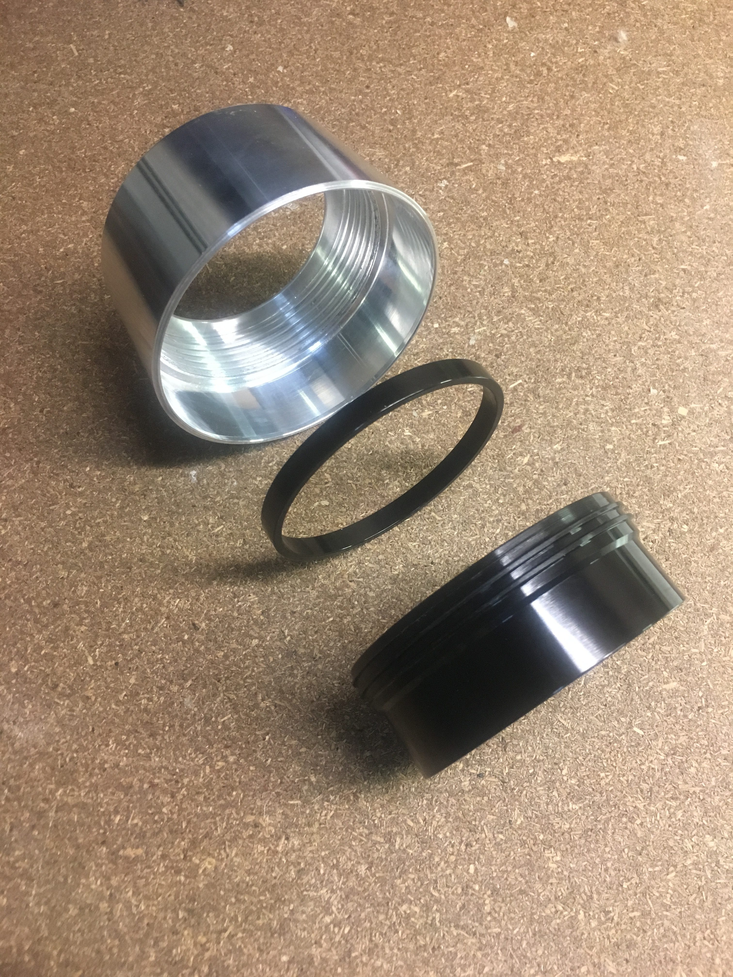
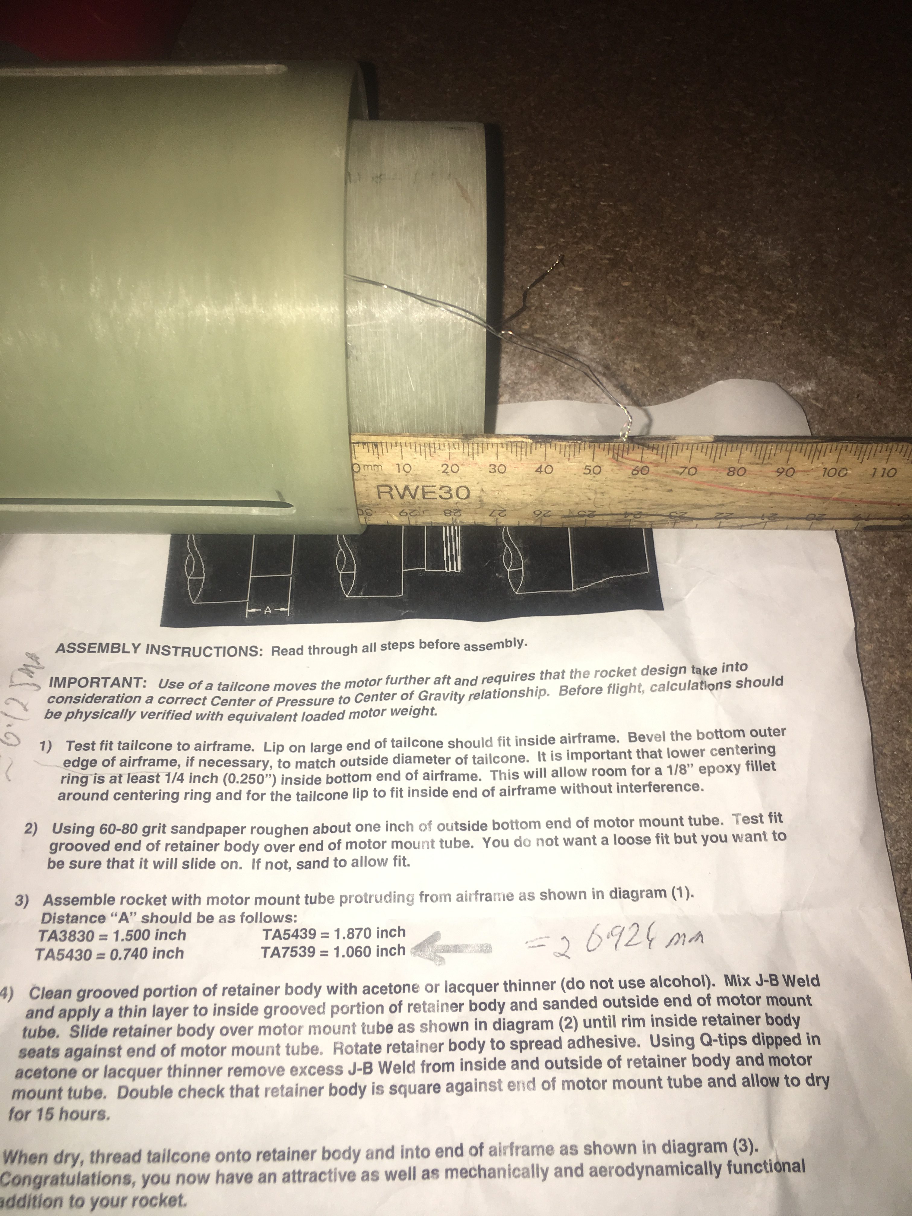
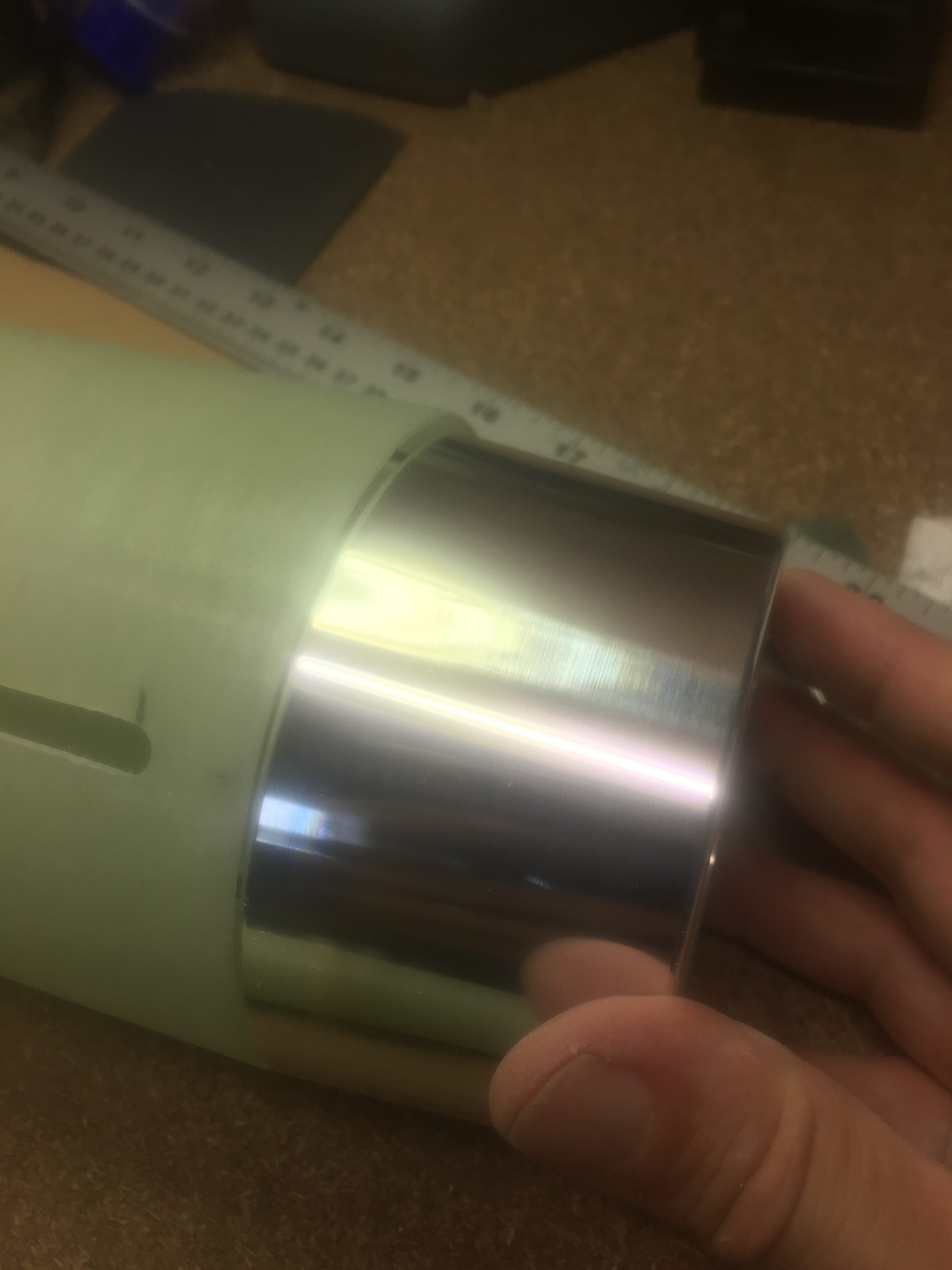
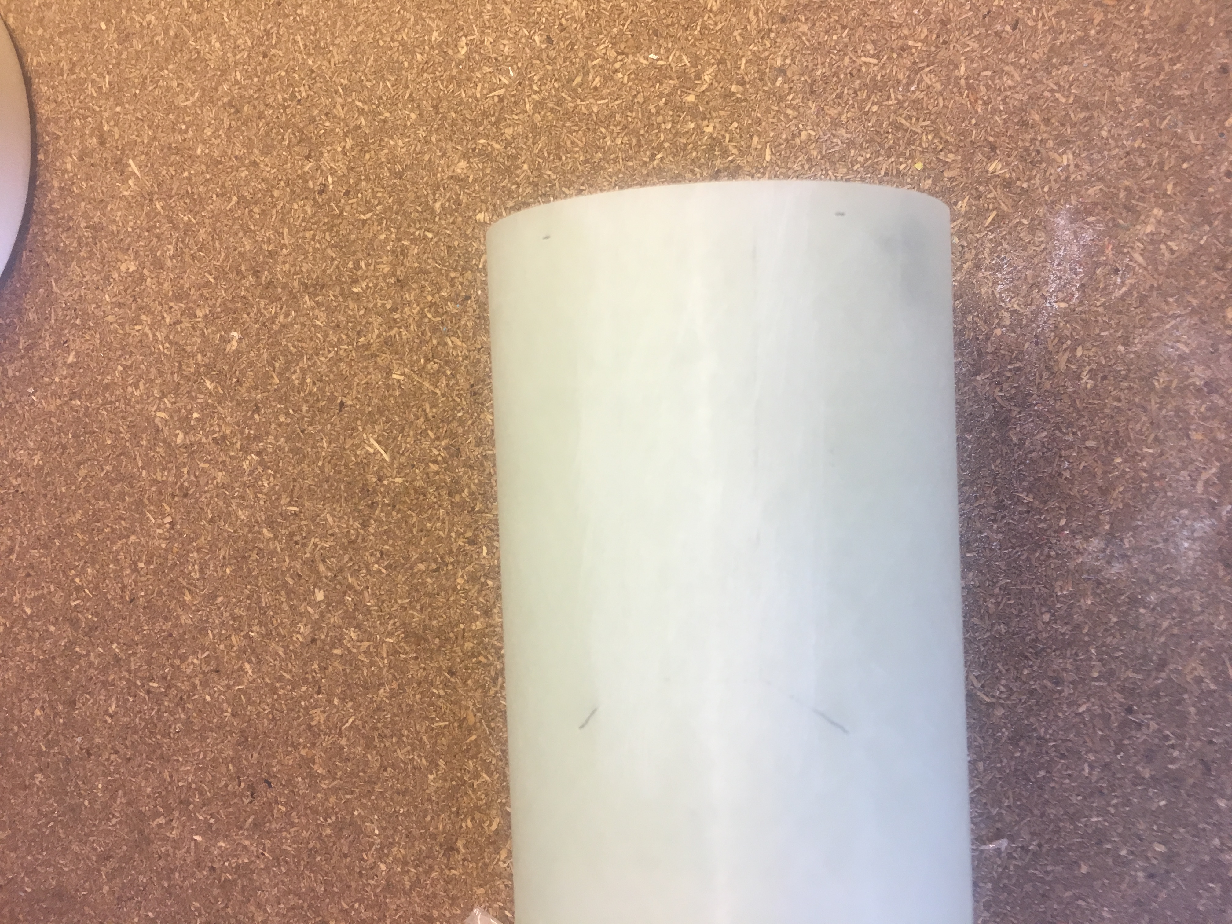
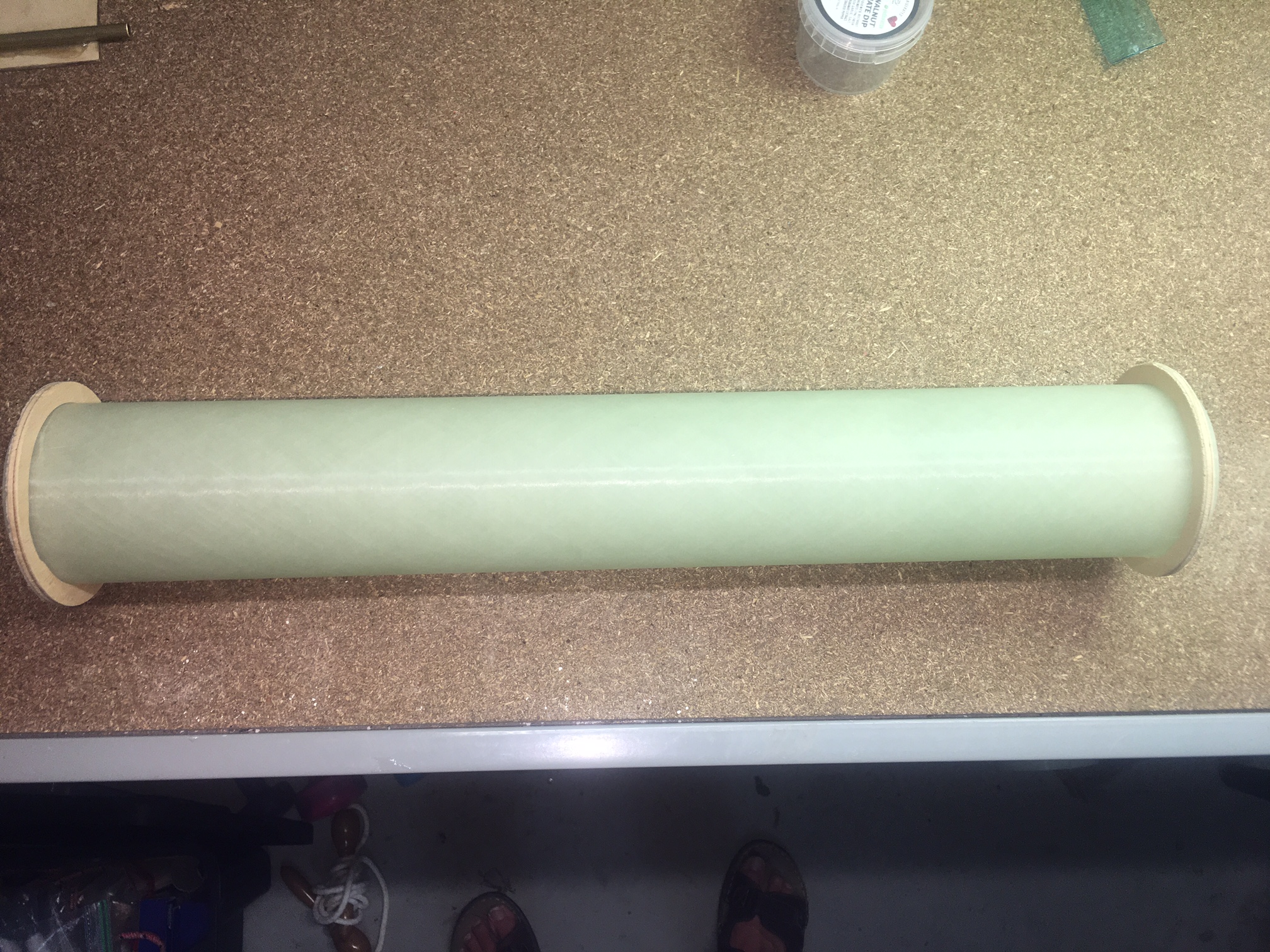
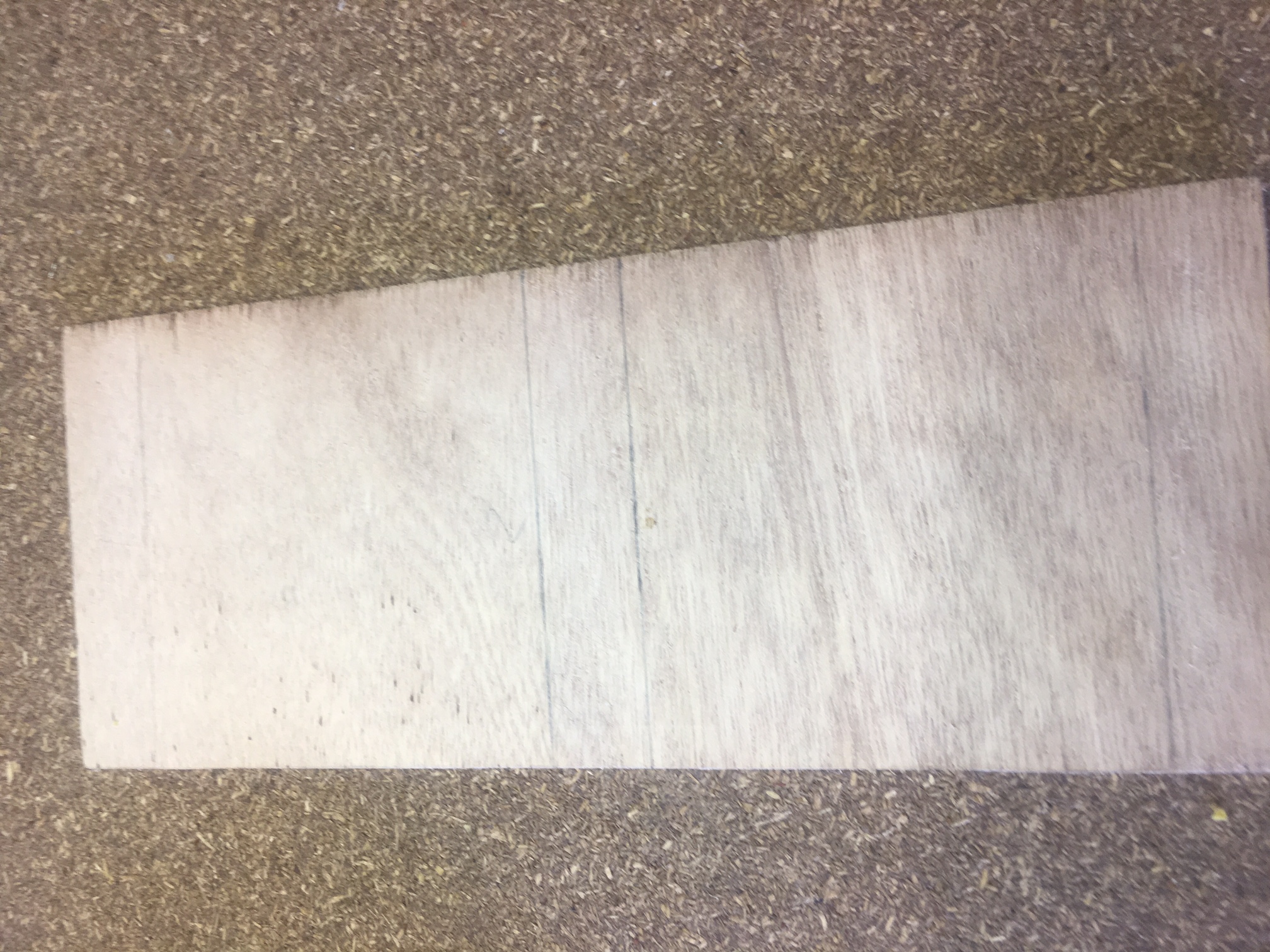
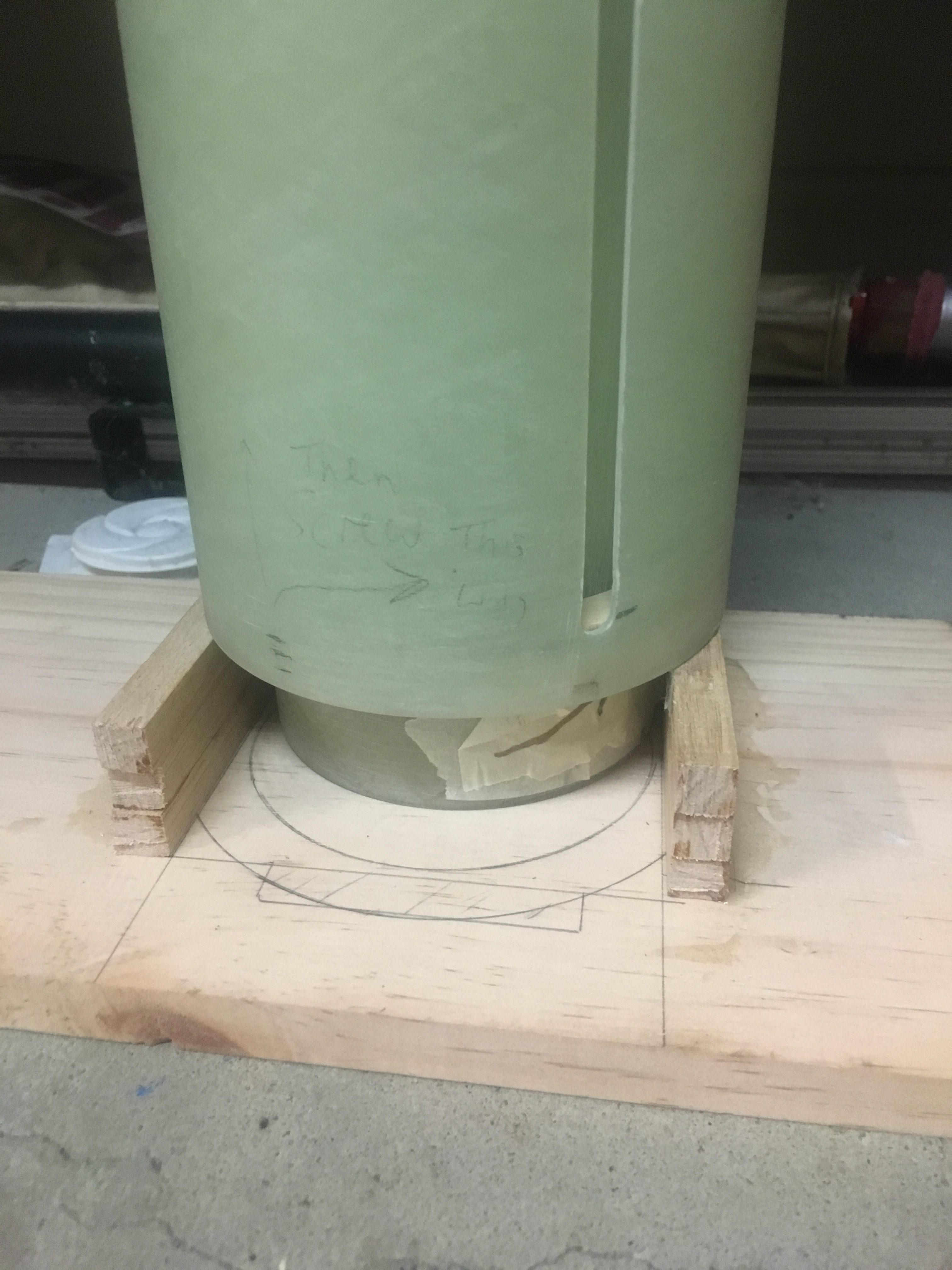
We checked that the motor mount was indeed sitting 27mm outside the end of the Air-frame. See the photo below.

Motor mount is resting on wood bottom.

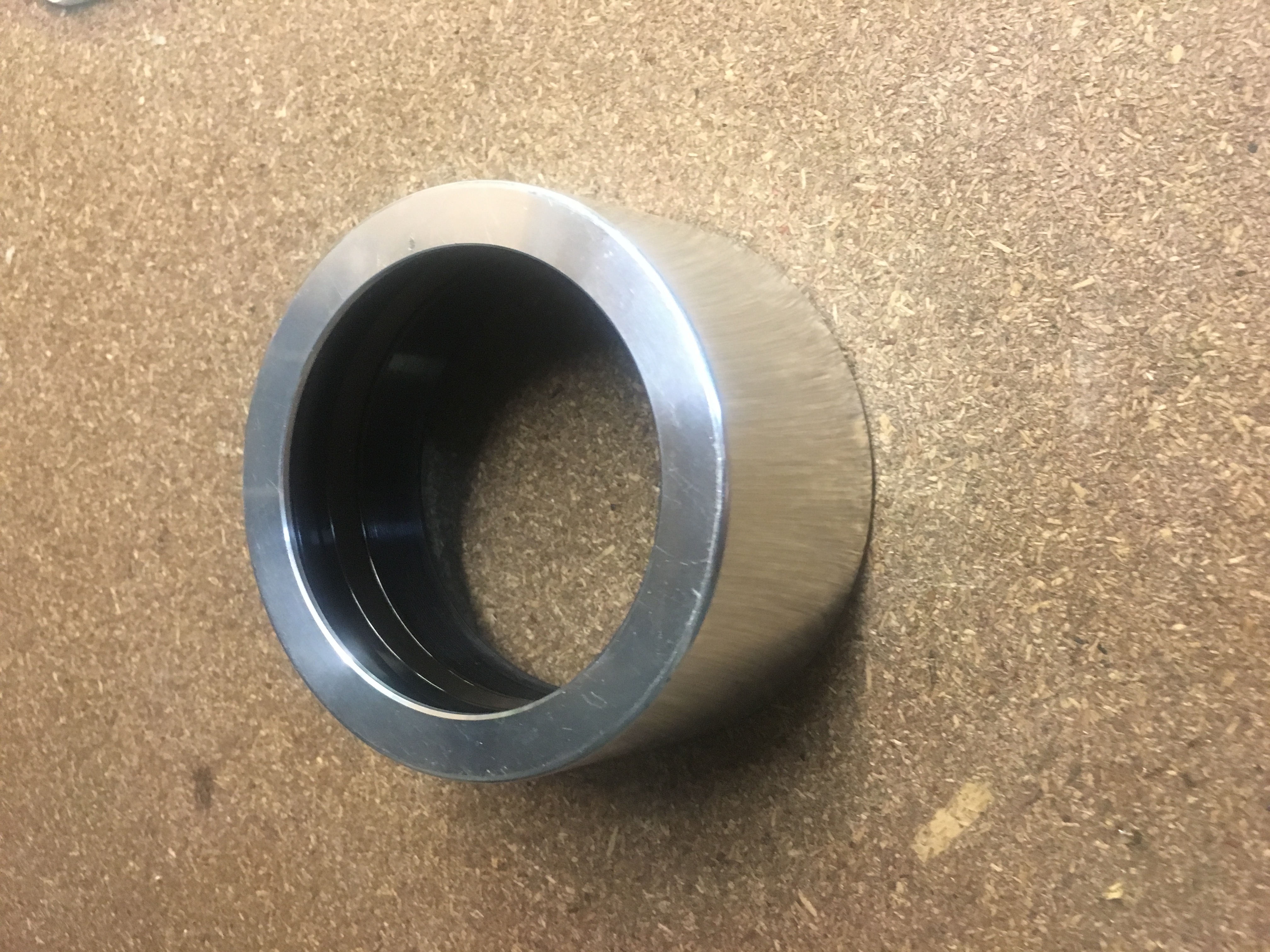
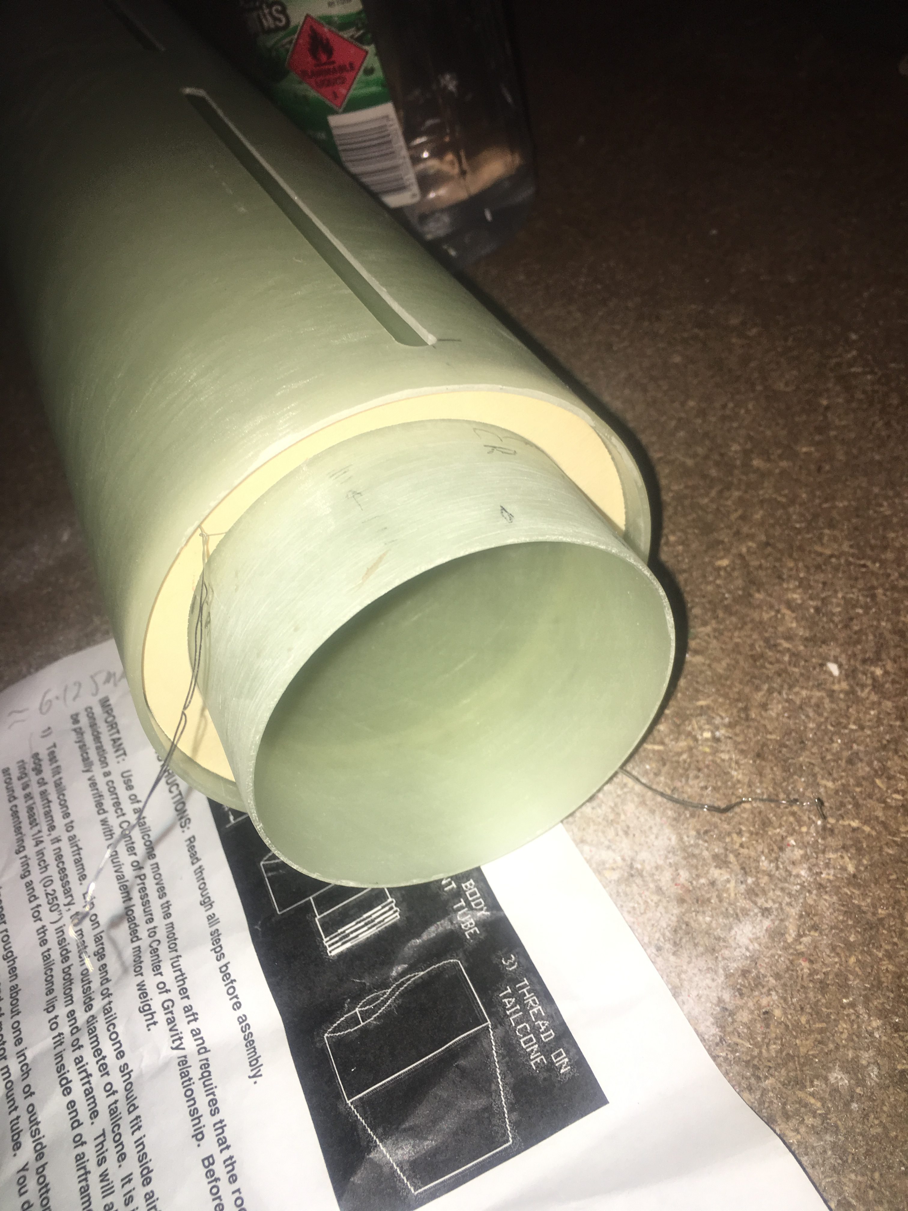
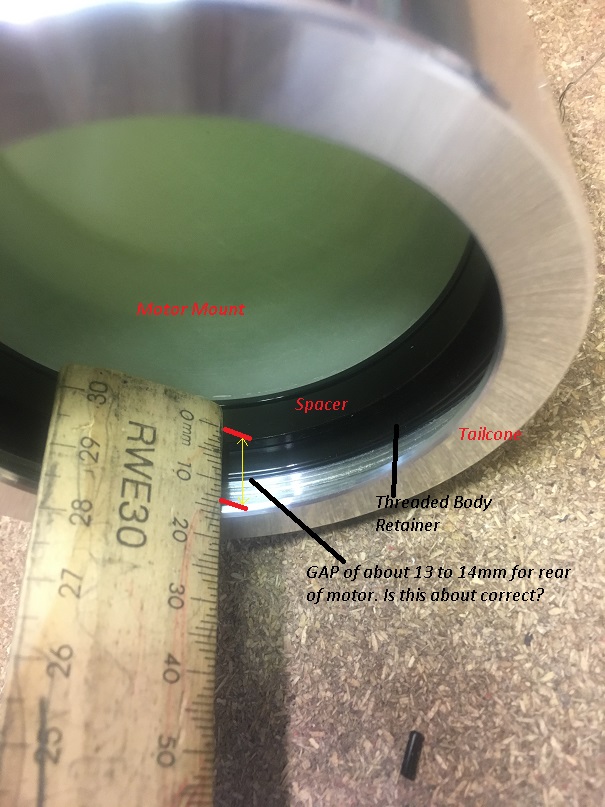
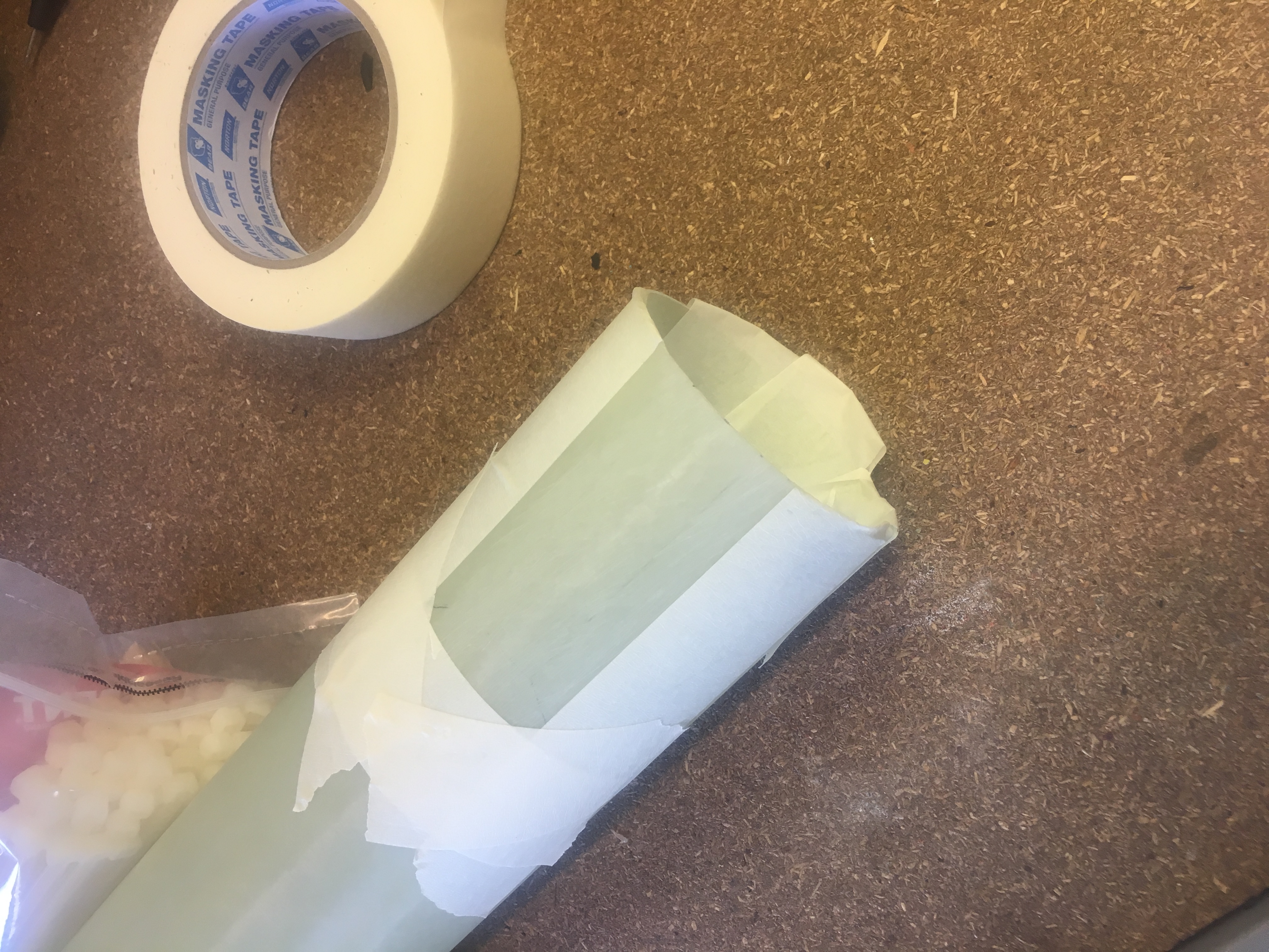
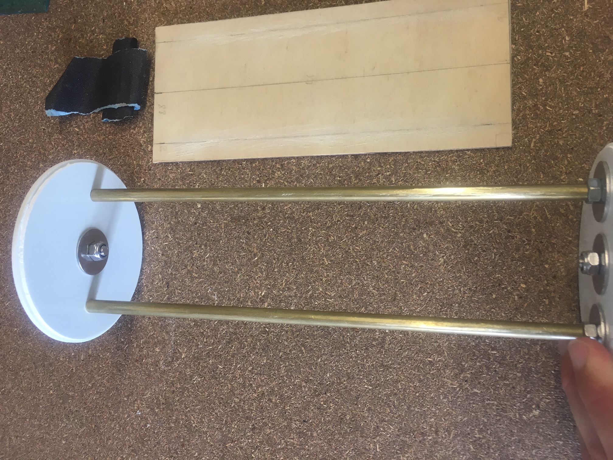
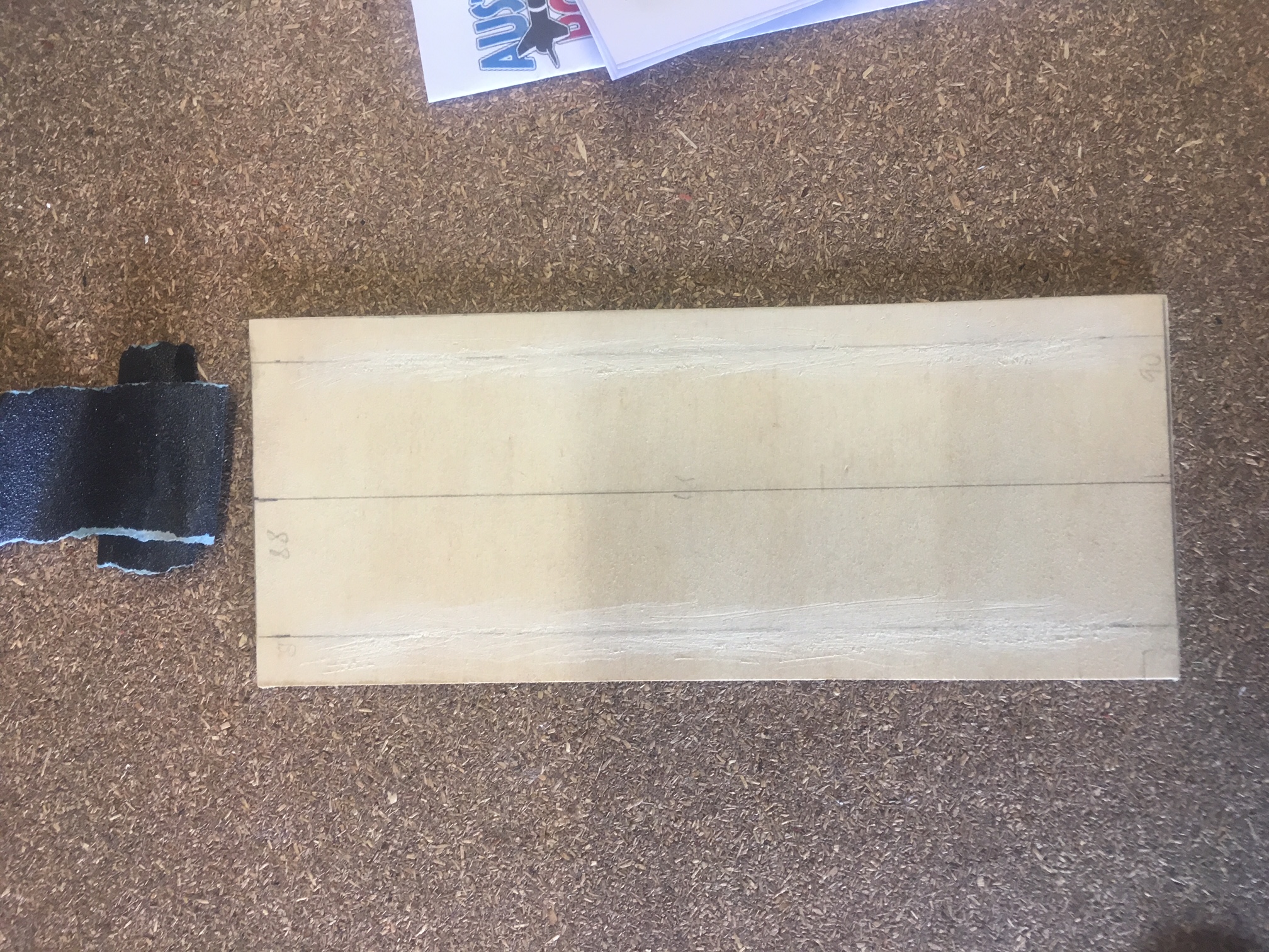
I had a look from the top to see how it looked.

Top view of 24hr Araldite


Preparations for gluing Motor Mount inside Airframe

A lot of work needs to be performed before we can attach (glue) the motor mount inside the Airframe. Below is a list of steps I have done:-

  1. Mark out where the Motor Mount needs to be glued in relation the end of the airframe
  2. Mark the upper/lower points inside the air-frame where we need to apply the Araldite.
  3. Choose the Glue to use for the joint. Will go for 24hr araldite because it is easier to handle (more viscid), doesn’t set as fast, so giving more time to apply and have a stronger bond.
  4. Cut off a piece of doweling and mark on the stick where it  is right up to the crucial part of the air-frame requiring glue. I rounded the ‘glue’ end to help in application of glue.
  5. Creating of a stand which will sit the rocket on to ensure that the Motor Mount protrudes from the Air-frame the exact distance – 27mm
  6. Find and set-up a place where we can erect the rocket to dry for 24hrs.
  7. Scuff the Motor mount where the Fins are eventually going to be attached.  Made sure surface is clear or dust and rubbish. Easier to do this BEFORE the Motor Mount is glued in.
  8. Make sure no tape left on motor mount
  9. Inspect the Top centering ring to be very sure it is glued sufficiently well.
  10. Tape down Nichrome wire to the bottom of the motor-mount so that it doesn’t get in the way

As you can see there is a massive amount of preparation before we even start applying any l glue.

Below are some pictures of the pieces worked on in this preparation.


IMG_2716

Construct the wood rest. It consists of single piece of wood with two 'walls'. Each wall is made of three pieces of wood (9x9) superglued. The airframe rest on the wall, the Motor-Mount drops 27mm down on to the wooden base.
Construct the wood rest. It consists of single piece of wood with two ‘walls’. Each wall is made of three pieces of wood (9×9) superglued. The airframe rest on the wall, the Motor-Mount drops 27mm down on to the wooden base.


IMG_2719


Image of Centering ring on motor Mount. 27mm mark on Motor mount must be inline with Airframe bottom.


Ground wood system where rocket will sit (vertically) while drying.


Image of air-frame with marking inside the air-frame visible. These marks indicate bounds of where I want to apply the Araldite

Tailcone and Motor Mount

I purchased an Aeropak Tailcone suitable for 76mm Motor Mount and 3.9″ Air-frame. The weight of all its parts together is 150 grams.


Here are some pictures of it.

AeroPak Tailcone all screwed together.
All parts of the AeroPak Tailcone.


I had to carefully sand down the motor mount external surface, approximately 1″ from the bottom to allow me to fit the threaded Aeropak mount component on. See pictures below.


Sanding down the bottom part of the Motor Mount with Sandpaper (GRIT 80).

I had to sand, then test, then sand multiple times, to ensure I didn’t over-do the sandpapering.

Testing the threaded Tailcone motor-mount adapter to see if it fits.

I have to clean the motor mount, remove the fibreglass dust to test joint and to ensure it is ready for gluing, later on.


Trail assembly of Tailcone on Motor Mount

One of the very important steps I have to do soon is to glue the motor mount (via top Centering Ring) into the main Air-frame tube. I have to be particularly careful here because we want to have the motor mount sticking out just enough to ensure that there is adequate room to install the Aeropack Tailcone. So here I am conducting a trial Dry-run installation.


Motor mount sticking out by 1.06" which is about 27mm
Motor mount sticking out by 1.06″ which is about 27mm


Side-on photo of install. Notice the Centering Ring is pushed in about 0.25" (6mm)
Side-on photo of install. Notice the Centering Ring is pushed in about 0.25″ (6mm)
Screwing on the Tailcone


As you can see here, I’ve used wires to allow me to remove the AFT Centering ring, which I’ll need to do at some point during the install.

Measuring gaps when fully assembled and checking that a motor would be able to fit.

I’m reasonably confident with it, but going to double check it.


Gluing the Bridle to the Motor Mount

I’ve started Step 1 of the Rocket build.

Step 1 of instructions


I decided to purchase a Syringe pack of 24 hr Alaldite glue. I choose 24hr glue because it offers strengths up to 150kg. I choose to get it in syringe form to help with the delivery of equal amounts of Part A and Part B.

I was very careful to follow the instructions. The instructions said to mix it for a minute and then let it rest for 5 to 10 minutes. So I did this.

Before doing any gluing I marked 7cm down the motor mount, so I would glue it in the right place. I also marked the strap.

Measured/marked where the Bridle is to be attached.

I was very particular about the GRIT of sand paper. I wanted to ensure I had low enough grit to ensure I get a good join.

60 Grit Sandpaper
60 Grit Sandpaper

I sand-papered it over a larger area than the strap because the glue will spread out beyond the Motor Mount. Increased surface area, increased strength.

Scuffed the Motor mount with Grit 60 sandpaper.


Then I cleaned the motor mount of dust.

Motor mount cleaned of dust.

I wanted to make sure glue did get everywhere I don’t want it, including INSIDE the motor mount. So I’ve taped it well.

Taped up the Motor Mount, to ensure glue doesn't go where I don't want it to go.
Taped up the Motor Mount, to ensure glue doesn’t go where I don’t want it to go.


Following the instructions on the Araldite, I applied glue to both materials.

Araldite applied to both the bridle strap cord and the motor mount.


Then I brought the two together and used making tape to keep the two together as it dried. The glue job was complete at 16:00. So by tomorrow morning it will be dry. It won’t be at it’s max strength, but it will be enough to start on the other end of the strap.

Bridle Strap cord secured to the Motor Mount.

I will probably apply more araldite over the cord, below where the centering ring is to be, to get increased bond strength.


The Centering rings

The Centering rings are what we use to attach the Motor Mount to the Air-frame. The Centering rings provided did not fit the Motor mount, too tight (this is not bad). So I very carefully sanded them down by hand, as evenly as possible. Every few minutes I would check to see if they would fit. The top centering ring is notched, to slide over the Bridle cord. So I marked the top of the Motor mount as ‘Top’. And I marked the bottom of the Motor Mount as bottom.

Eventually after about 30mins of patient sanding I was able to slide both centering rings over the Motor Mount.


Centering rings on Motor Mount - Dry Fit.
Centering rings on Motor Mount – Dry Fit.

Building the Avionics Bay

I’ve already started building the Avionics bay, admittedly a little early in the steps, but decided that it would be good to see how it fitted in with everything else. There was a bit of gluing here, but decided that constructing parts of the Avionics Bay is not going to stifle the remaining construction of the rocket.

Markings on wood tray to help with alignment of the brass tubes
Making sure everything lines up well.


Roughing up the wood to ensure really good glue joint.
Brass Tubes areldited to the wood
Brass Tubes araldited to the wood

I wasn’t terribly with the result of the tray. I should have laid down some tape to ‘restrict where some glue could go.  I’m sure it would work (be strong enough), but from a cosmetic point of view – not good.

So, I’ve decided to make my own tray. See pictures below.

Wood pieces, all identical

Wood pieces, all identical

I had to take extra care in creating these wood pieces. I performed just TWO cuts of three pieces sticky-taped together in a special decide to ensure that all the cuts would be square. Because I cut them altogether, this meant they were precisely the same length.

In terms of drilling holes, I just took my time and very carefully ensured the drill was level and the markings were as close as possible.


Tray cutout with markings for where wood is to be glued.


All components glued and everything assembled.

This to me is a much nicer job.