The Launch Electronics sole purpose initially is to provide a safe reliable means of launching our current model rockets. We could easily go for a wire based method with a box with some buttons…a very simple, but effective approach.
…However it was decided that this is not the best approach because we need to look at developing some of the technology required in later launches, including the Rockoon. We don’t wish to however build everything right now, but, but start building something that can be added and extended later. The High Altitude Balloon Electronics worked very well, so decided to draw from that.
The High Level Design
The solution will consist of three components:-
1. The End user device (ipad or iphone), which we will refer to as the Launch Console.
2. The Ground Station is the system the iphone/ipad connects to. The Ground Station will connect to the Remote Launch System via the radio modems
3. The Remote Launch System which will have all the necessary electronics to power, up, test, arm and launch the model rocket.
More information on each of these components is below.
Launch Console
The operator will only require an ipad which can connect to the Ground Station which will act as a Wirelss Access Point. The operator will be able to use a browser to access the Launch System Software.
Ground Station
This will be a small computer, looking at using a Rasberry-Pi 2 Model B. It will have its own RTC module, USB Wifi dongle and be connected to a RFD868 radio modem via serial. It will run PHP/Apache and use SQLLite3 database to store data. The systems used in the balloon launch used a BeagleBone Black. OpenStreetView was a bit sluggish, and so we hope/expect to perform a little better this time. with the Rasberry-Pi.
NOTE: Open Streetview is not required initially for our launch systems, but will be required later down the track.
Remote Launch System
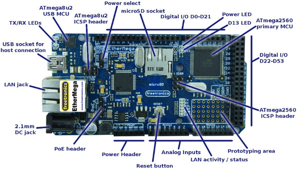
Using something light and something that isn’t power hungry and has lots of GPIO is very important. That is why we have decided to go for EtherMega 2560. A picture of this is below:-
Picture of controller used for Remote Launch System
We will initially create a single PCB with relays and Switch Mode PSU to power the relays and RFD868a modems. Later we will add another PCB (sandwiched in between) with GPS, RTC, Air pressure sensor and IMU and Camera.
Two PSU will be required, one to power the micro Electronics and another to power the Igniters.
Below is a picture of how I envisage everything will ‘fit’ together.
High level design
Summary
One of the great things is that as we progress with bigger model rockets, the launch system will get more and more testing, which will help give us the confidence when the Rockoon is ultimately launched.
Just a short post to show the launch pad with the launch rail attached to the platform. It is a 2.5 m length of 1010. I still need to put in a blast deflector and a stopper for the rocket to rest upon. Here are some pictures
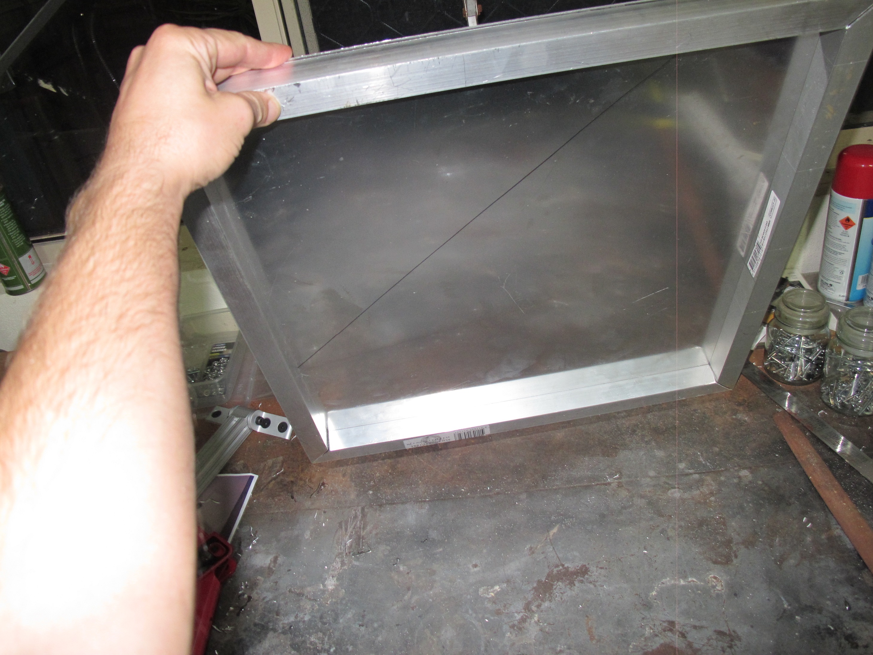
The platform sheet is particularly heavy and sharp and hence dangerous to handle. It is very easy to cut oneself on the edge of it. To deal with this, we have decided to attach 1″ square profile Aluminum tube. We have done this by cutting four lengths of tube and cutting out each end a 45 degree cut to ensure they connect together around the perimeter of the Aluminum sheet neatly. We pot riveted these square profile tubes to the sheet.
Pot rivets holding tubing on to sheet
Square Tube riveted to the plate
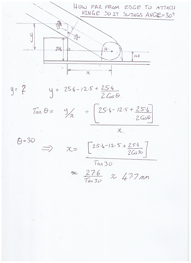
Next I wanted to install the leg hinges. I want the platform to be about 40cm above the ground and so with a leg length of 80cm, this means the legs must subtend an angle of 30 degrees with the platform. The side aluminum tube will provide a place for the legs to rest against to ensure 30 degrees angle is met. To get the angle of 30 degrees, we must place the legs a certain distance away from the tube. Please see calculations below.
Calculations to find hinge distance
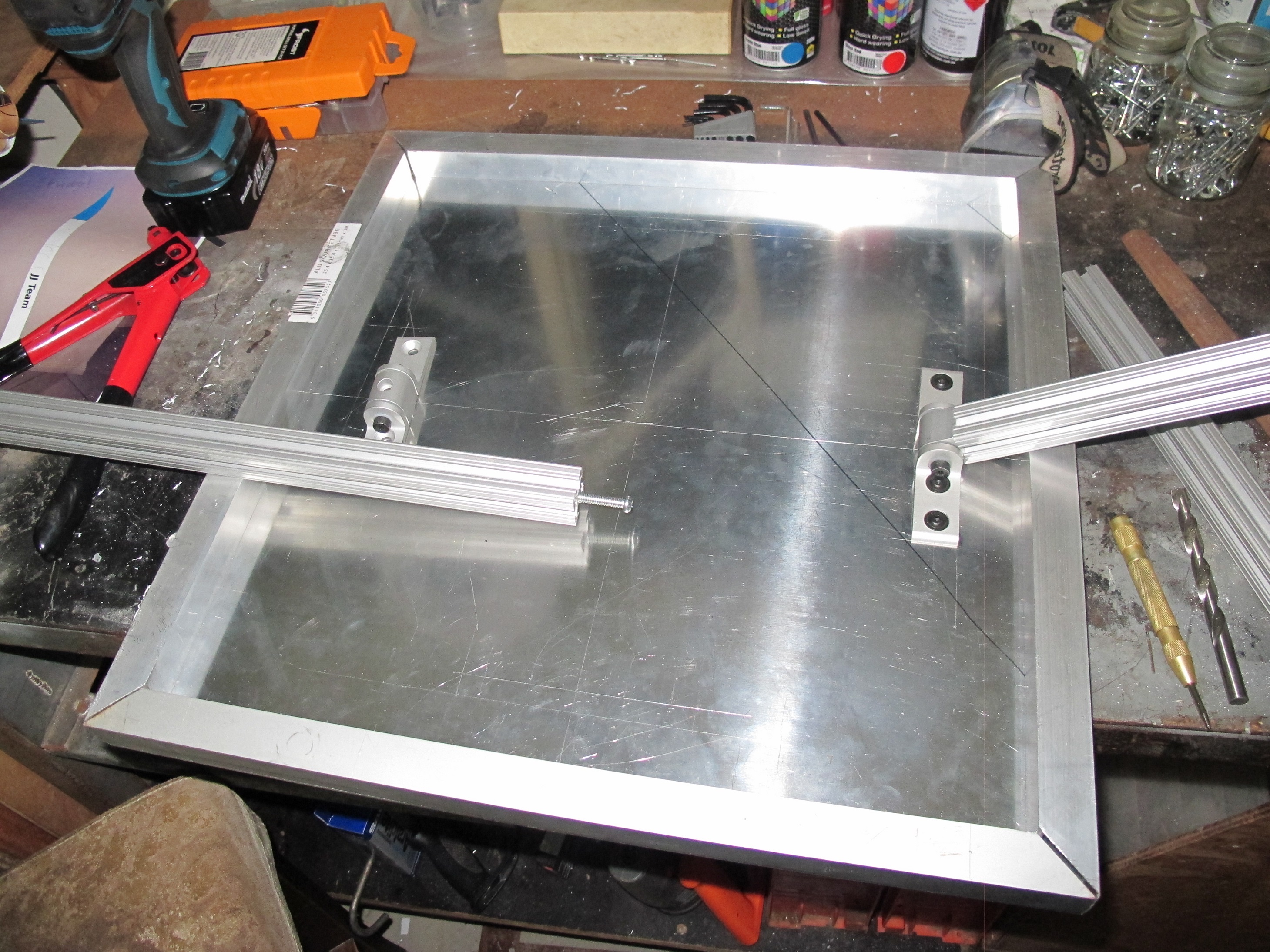
I’ve started marking holes around and installing the hinges. See the picture below.
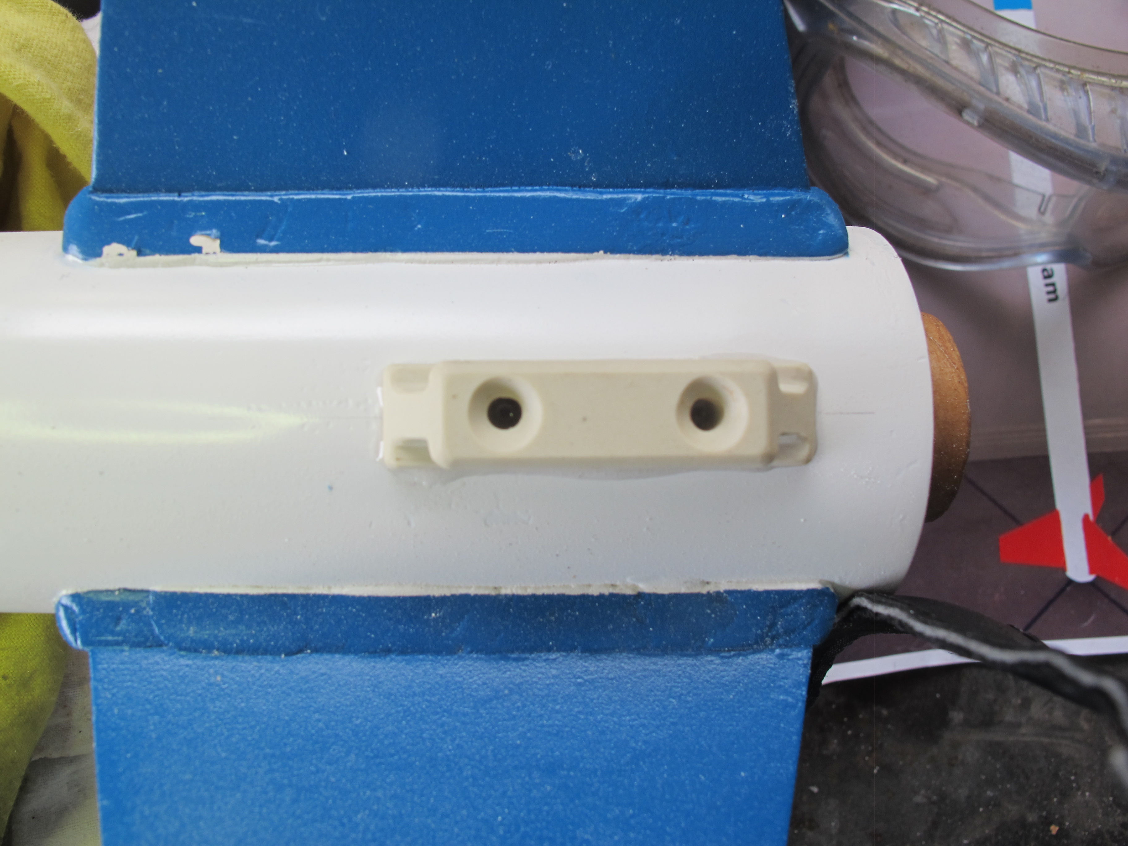
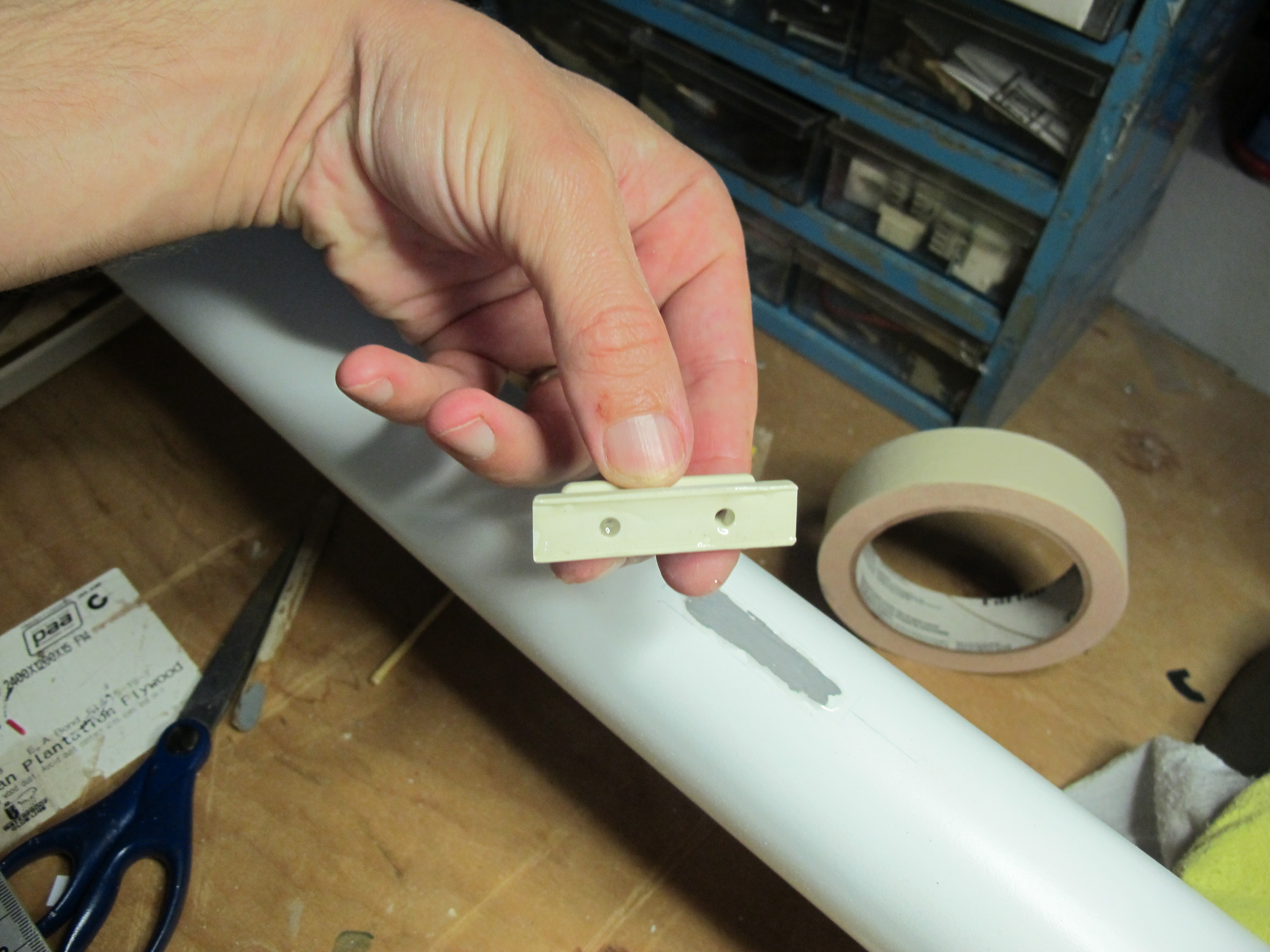
The rocket hasn’t been completed…the launch buttons haven’t been installed. There is a reason I’ve decided to hold off on the install of the buttons/lugs is to complete the launch pads.
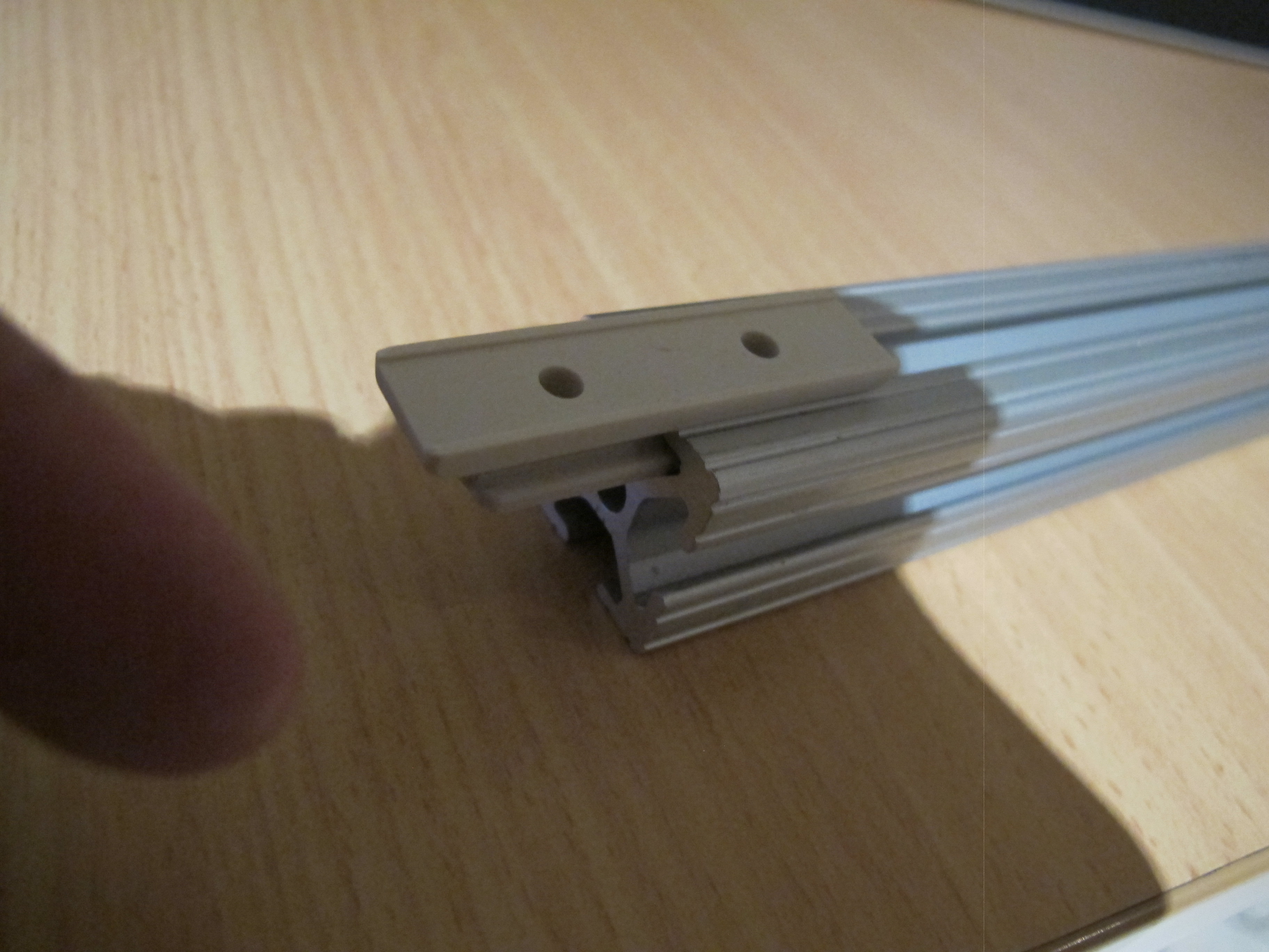
For those who do not know, the launch buttons/lugs are what we install on the rocket to guide it up the rail. See Picture below of a lug inside some 1010.
Launch Lug in 1010 Rail
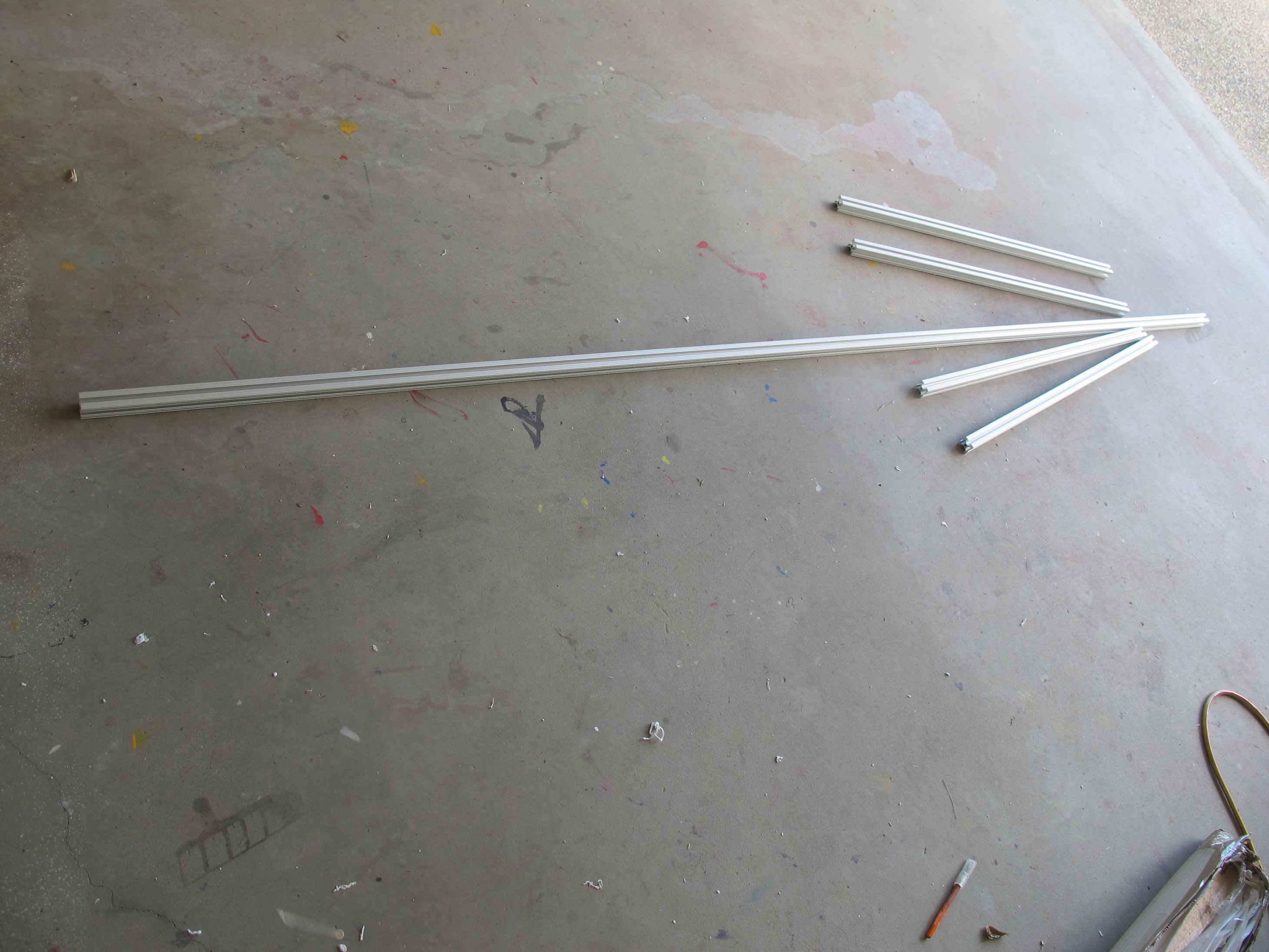
Anyhow, I’ve received all the parts from 8020 that I need. A mong these parts is:-
4 x 80cm length of 1010 for the legs
1 x 25cm lenght of 1010 to mount 4053.
1 x 2.5m length of 1010 for the rail
An assortment of T-nuts and screws
1 x 4053 – 180 degree Pivot Bracket Assembly with “L” handles
4 x 4168 – Living Hinge Assy 0 degree
4 x 4181 (0 degree Living Nub …one at each end of the four legs)
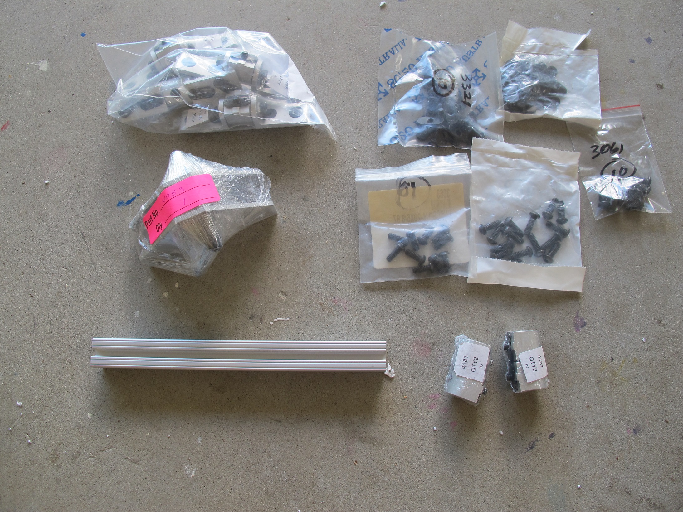
Pictures of these below.
Assortment of small 8020 piecesLong 1010 rail and the four legs
I need more parts and tools to complete this part of the project. I needed to obtain :-
Aluminum Sheet – 500 x 500 x 5
3 metre length of 1inch Square profile Aluminium tube
Tap & Die kit
Four M6 screws
25 x 3/16″ screws with nuts and washers
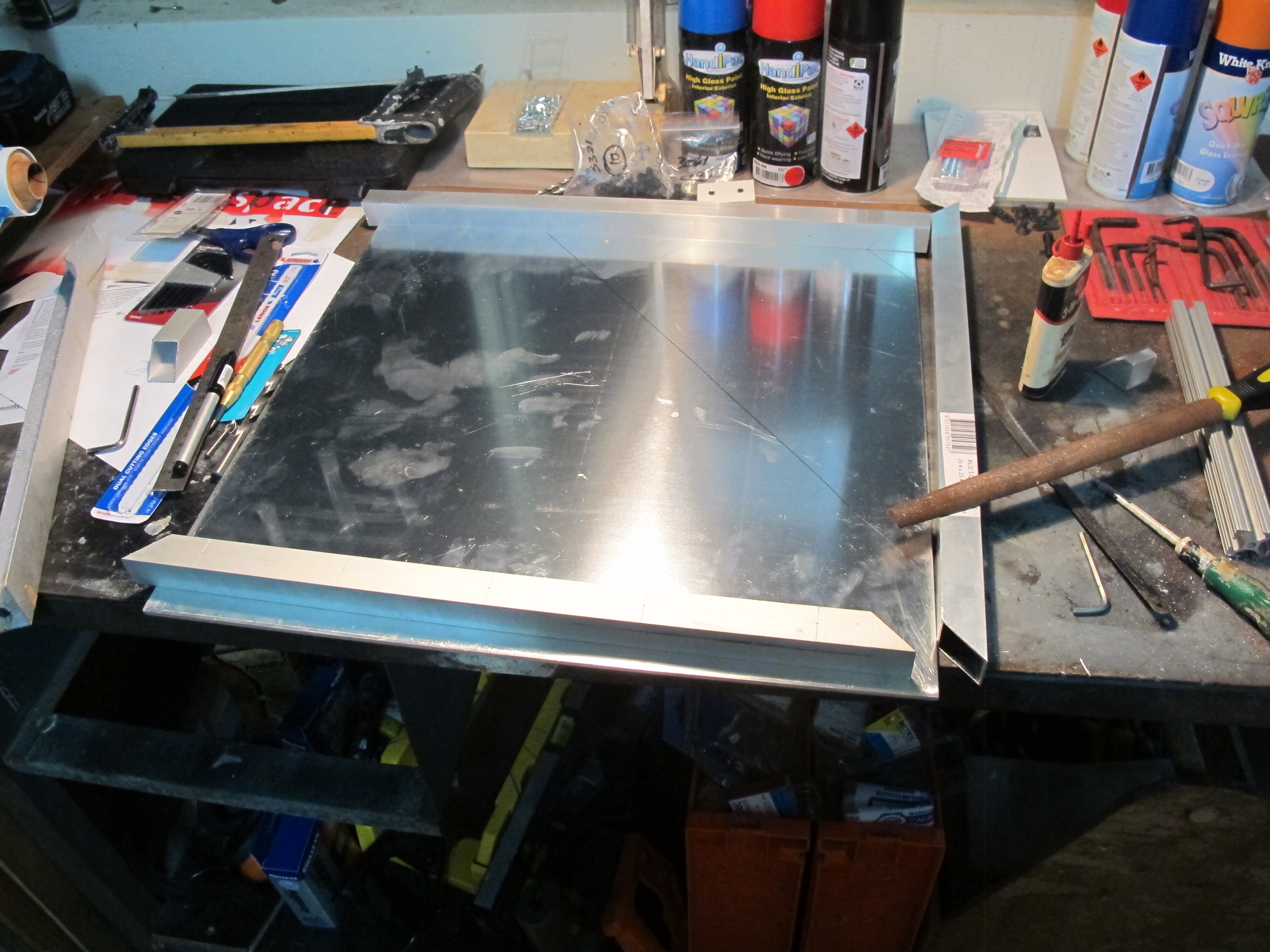
Below is a picture of the Aluminum sheet with some of the square profile pipe cut into pieces…almost ready for assembly around the rim of the square.
Aluminium sheet with square profile tube partially complete
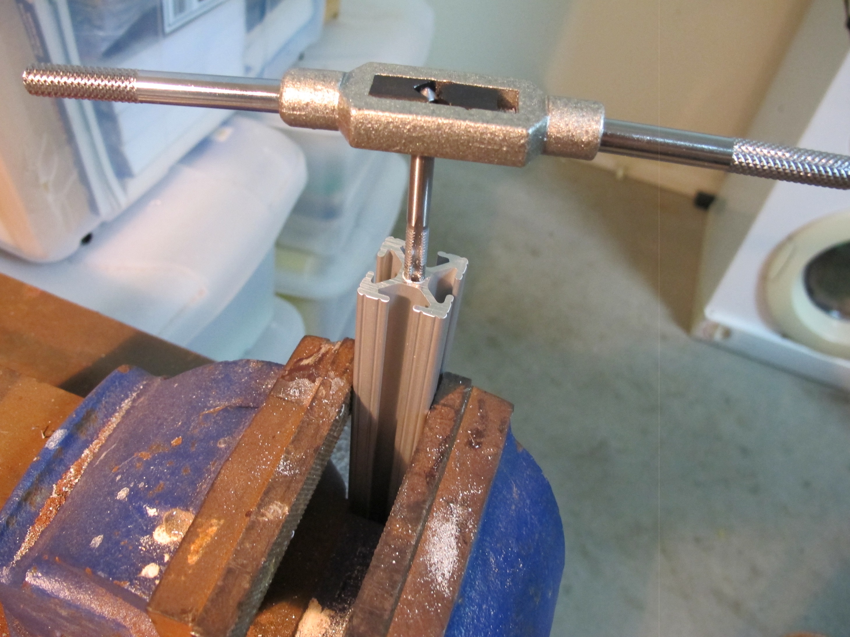
Below is a picture of me Tapping a M6 hole into the ends of the Legs.
Tapping a hole
The holes were already 0.205 ” which is 5.207 mm. This is not too large for a M6 tap job.
Below is a picture of all legs with the Part #4168 attached.
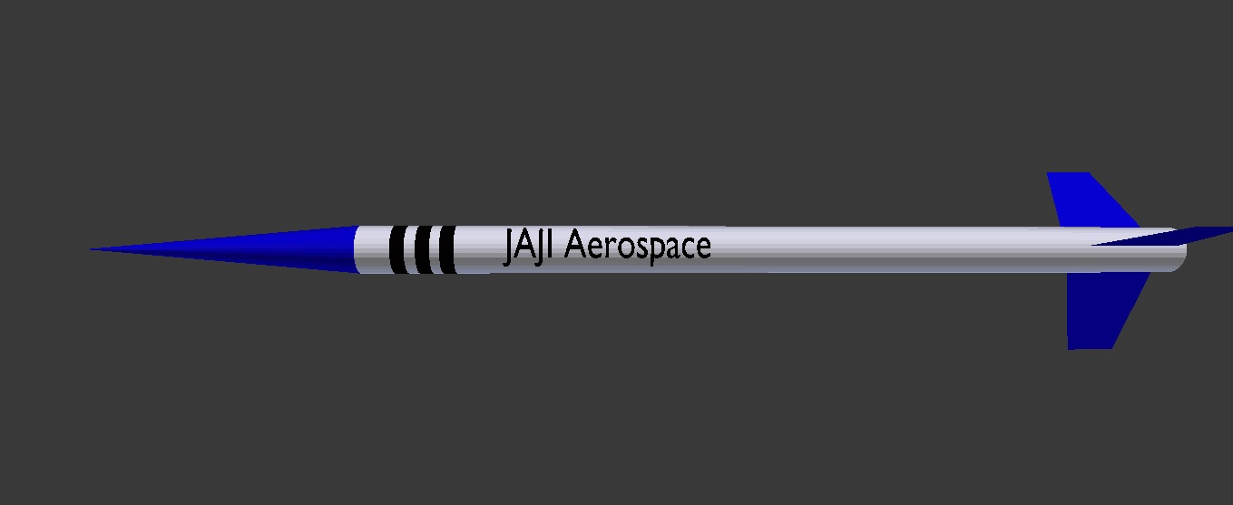
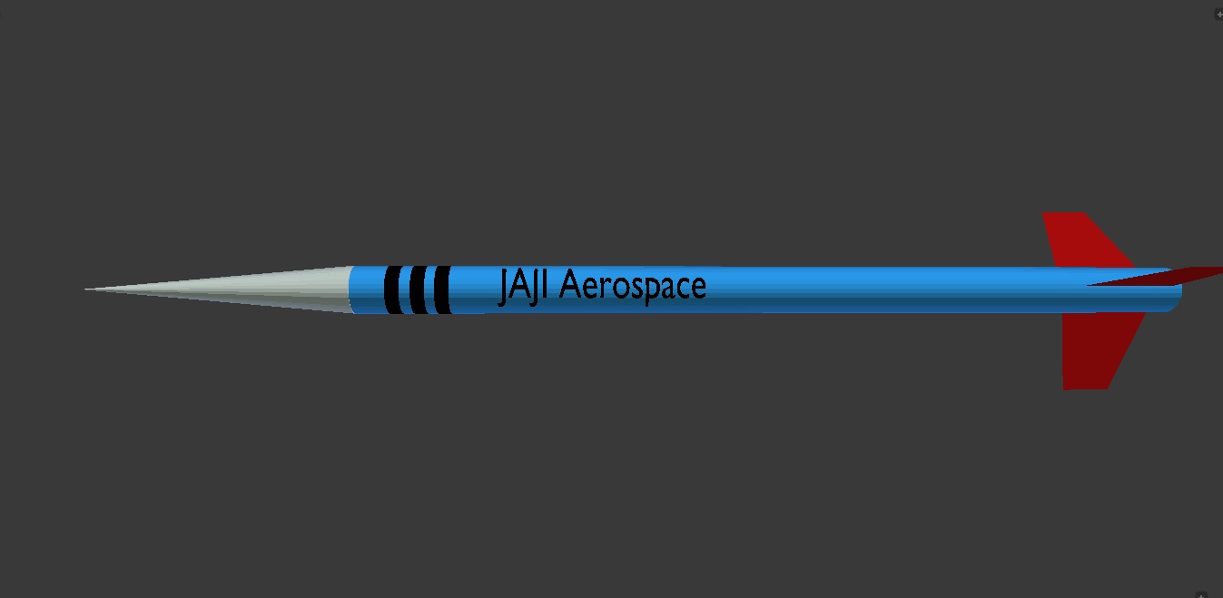
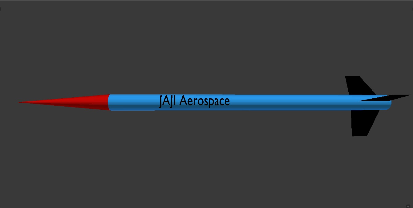
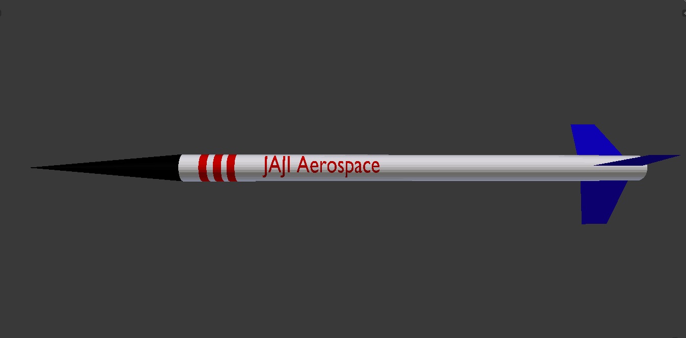
A number of designs were done up using Blender. I did this by measuring the rocket and creating a file. I then played about with different combinations. Below are some examples.
One of many designs.One of many designs.One of many designs.Jeremys top design
I also managed to figure out how to put some ‘text’ on the rocket tube to realistically show how it would look. Jeremy my son provided some possible designs and we ultimately adopted one of this designs; the last one shown.
The painting process was long and complex. There were times when I had to walk away to allow it to dry and then turn it over to paint more. Often I did very light coats, so as to avoid dripping. This meant I had to come back and do several coats though.
The basic steps followed were:-
Sand and clean up any imperfections in the rocket
Create a clean/free area (our garage) and put down newspaper
A place to paint
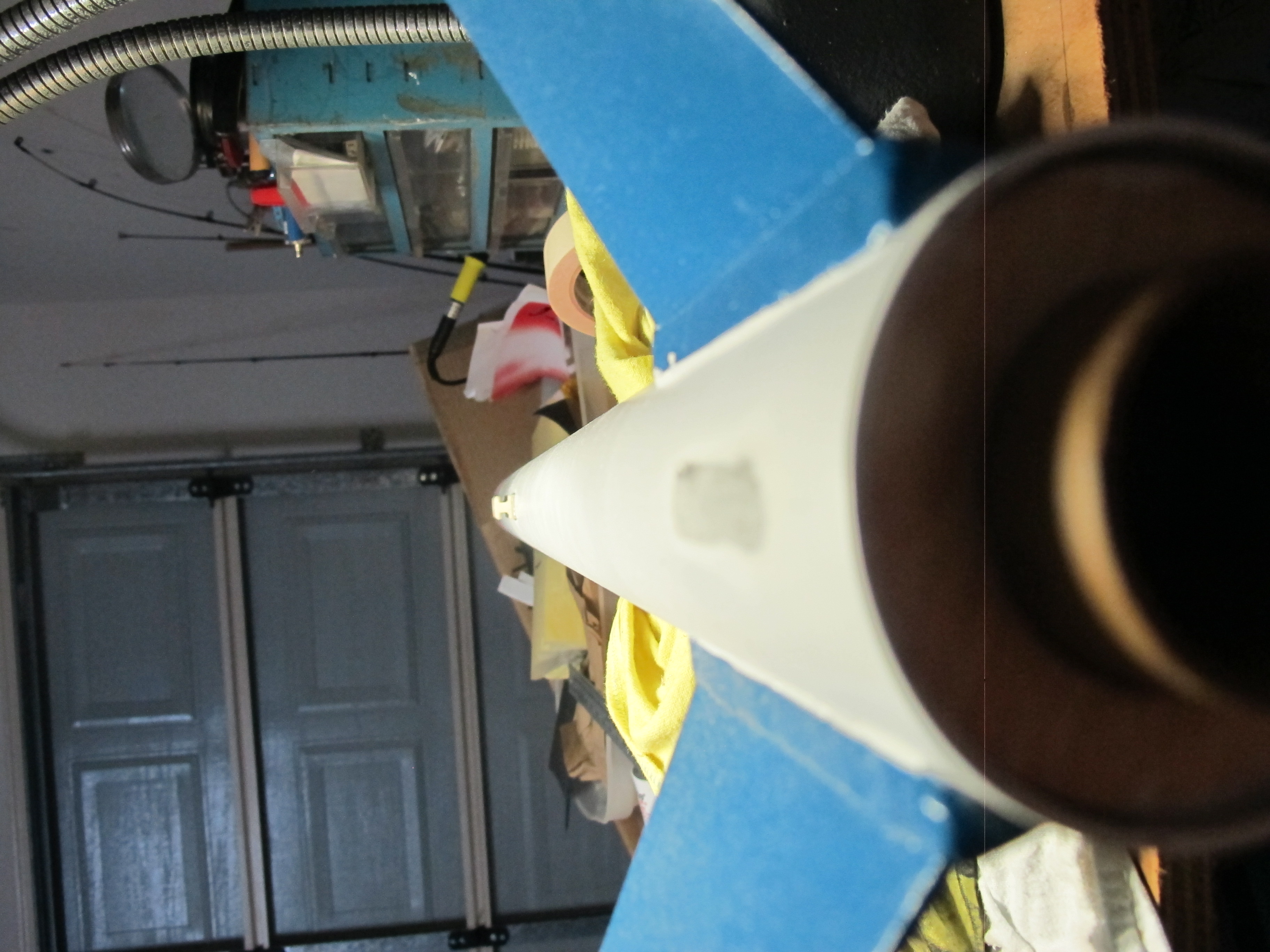
Prepare rocket on stands, with nose cone slightly withdrawn from tube and taped up together (in recess).
Cover up areas of rocket we do not want painted
Completed painted with white Primer
With Primer
Painted fins blue
Painted nose cone black
Painted body white
Covering up Nose code before painting tube.
Covering up Fins before painting tube.
Created stencil from a computer print out….using a scalpel blade. Carefully placed on rocket. Also attached bands to make the red stripes
Carefully cut out
Carefully painted red writing and stripes.
Almost ready to attach stencil
Part way through painting lettering and stripes.
Very VERY carefully remove tape and paper to reveal the finished item.