Category Archives: Design/Thought Processes

External Fillets for the Rocket

Preparation

Preparation is key to the success. I made sure we sanded the areas to be filleted with Grit 60 Sand paper, that they were then cleaned with Methylated spirits and then taped up.

Sanding with Grit 60 Sand paper.


Finished sanding - ready for cleaning.
Finished sanding – ready for cleaning.

All practice external filleting I had done so far had neglected the ends; it was more focused on the the main stretch. The width of the fillets needs to converge to zero at both ends of the fin on the air-frame. I did a simple plot y = 2x^2  on my printer and printed it out and used it to create masking tape pieces to stick at the fin ends. What resulted looks as follows:-


Pointing to the curved masking tape end. This should ensure a consistently shaped fin fillet.


Rocket all taped up, ready for filleting.


The Glue

We made a normal ‘peanut’ consistency batch of Epoxy. We decided to use the new syringes as the old ones are too sticky and hard to push.

We originally made 20ml/4ml of epoxy for one one side of fins (lower and upper fins). We found that there was probably about 6ml of epoxy left over – so wastage. In future Epoxy runs, we’ll make it up using 15ml/3ml of 105/206.

Epoxy in new syringe, already to go.


The result

Back fin.

Back fin.

Front Fin
Front Fin
View from back of both fillets.

Fairly happy with it. I am going to need to build up the back/front of fins to ensure smooth transition. Not quite as good as I had hoped there.


Internal Fillets – Fin/Airframe

Thought processes

I decided after much internal debating to create a fillet between Fin and the air-frame. (Though it is more from the previous fillet to the air-frame). I decided to do this because the instructions for Katana 4 mention Internal fillets to the Air-frame. I know some people don’t bother with these fillets and I can probably get away without having them for smaller motors. But if I want to fly larger motors or lots of flights I might experience issues with fins/air-frame.

So much focus has been on attaching the fins securely to the motor-mount and air-frame that it is easy to forget other possible modes of failure (other than fins coming off). I was a little concerned that the air-frame, being as thin as they could possibly fail due to loads. So I thought it would be prudent to strengthen the air-frame around the fins with this fillet.

The Epoxy resin

I decided I didn’t want to go through with the 105/206 again with leakages. The space is much more restrictive and so bogging up ends could be difficult. The fillets don’t need to look nice and so I decided to go for 105/206/403 – just short of peanut consistency.  I decided to go a little under peanut consistency, so that the epoxy could ‘droop’ down and fill up the gaps. I wanted a droop more than a drip so that I wouldn’t get a large mess.  After about 20 mins of curing, it’s viscosity increases sufficiently that it stops drooping.

The tools

It was too hard to use really thin tube – 5 mm in diameter, despite the obvious advantages; it can easily fit down into the cavity. The problem is that the Epoxy cannot be easily delivered due to the viscosity.

So I had to go for 6 mm internal diameter tube. The extra mm makes a big difference. A problem with 6 mm tube is that I couldn’t attach the normal doweling to get it down into the cavity. It just won’t fit. 6 mm tube by itself is so snug that it somewhat deformed (squashed a little). I also wanted an arc (1/4 circle bend) at the end to direct the epoxy into the gap between the air-frame and the fin and the only way I could do this was with 3 mm diameter copper rod that I bent into shape. I used narrow lengths of Masking Tape to bend the tube at the end to the copper rod.

6mm Internal diameter plastic tube on 3mm copper rod.

It worked! I could then withdraw the tube and push the epoxy in and was even able to just see the epoxy coming out, so I could confirm that it was going into the right place! Very happy with this.


Preparation

Bench ready for Gluing.


403 Filler ready for use.


Mixing 403 filler into 105/206 mix.


Internal fillets done

It is a bit hard to notice, but there are internal fillets done here.

External Fillets – Second Trial

Practice makes Perfect

I wanted to practice the external fillets again. I have only one chance at this , so the procedure needs to be clear in my mind.

My Test bed

I nailed two pieces of wood. Then I used a 10mm aluminium rod to accurately measure 10mm lines on each edge. Then I taped up the wood, so that fillets can’t extend past 10mm. Below is a photo of this set-up.

Test bed - to practice external filleting.
Test bed – to practice external filleting.

The Epoxy

I wanted a proper peanut epoxy mix – no drooping at all, no dripping. So I went for the 105/206/403 mixture.

I mixed 15/3 of 105/206. This did two 15cm lengths with a little bit left over. With 6 fins (both sides) we have 204cm of fillets. So we will need about 7 times this quantity of epoxy. i.e. 105/21. Though we are very likely to do this in 6 (possibly 3 if we are feeling extra confident) jobs.

I was careful not to introduce any air while mixing and I carefully filtered the 403 twice to ensure that I didn’t have any clumps. I had about 10 mins of 20 mins time left to apply the epoxy to the filleting area and create the required profile.

Delivery of Epoxy to Join

I don’t need to pass this epoxy through any tube (like before), just from a syringe.  I just packed it in and then squeezed it into the spot. I made sure that I was putting in enough epoxy along the fillet join.

105/206/403 epoxy mix loaded into syringe, ready for filleting.
Applying epoxy to join. (Sorry it is out of focus)
Left over Epoxy mixing after using PCB tool to create fillet profile.


Epoxy left to dry for 12 hours. Notice how tape has been removed.

Sanding

After it had dried, I did the sanding using a specially made sanding stick. I made the sanding stick by Gluing Grit 60 Sandpaper to one end and Grit 240 at the other end. I used Selleys Glue to attach the sandpaper. It had to dry overnight. (Yes, lots of waiting).

IMG_3532

Practicing using the sanding bar

The (almost) Final Product

Here are two pictures that compare one side (sanded) with the other side (un-sanded)

Un-Sanded Fillet
Un-Sanded Fillet
Sanded Fillet
Sanded Fillet

The finish is excellent – very smooth. There is still a line where the masking tape was. This line needs to be removed by using filler to bring it to the fibrerglass air-frame.

As a reminder, this effort is being made because we want to reduce Interference drag which can have a significant impact on a rocket’s performance.

Removing the line

My neighbor suggested the filler as a technique for removing the line. He had a go on this test fillet I did. I took some pictures of what he did. (Of course I’ll be doing this myself when it comes to the real thing).

Side on view of fillet sanded and filled in and painted with primer.
Very smooth finish after building up edges to remove tape line. Painted with primer to help bring out any imperfections.
Very smooth finish after building up edges to remove tape line. Painted with primer to help bring out any imperfections; if any.

Good aye? Can you tell where the fillet starts/ends?


Katana 4 – Material Weights

I’ve weighed all the components of the rocket. I’ve tabulated them below.

To identify which parts I’m referring to, I’ve included a picture of the components on the installation instructions.


front-page-components


Booster Airframe: 1494 grams

Motor Mount: 443 grams

Payload Airframe: 721 grams

Nose Cone: 349 grams

Nose Cone Coupler Tube: 222 grams

One Top Fin: 151 grams

One Bottom Fin: 113 grams

Bridle Strap: ~40 grams

Avionics Bay Fibre-Glass (52mm length): 60 grams

Avionics Bay (Wood + Bulkheads + threaded rod + nuts + washers + eye-ring bolts : 395 grams

Nose Cone Bulk plate + Eye Bolt + Nut: 90 grams

Avionics Bay Coupler (275 mm): 322 grams

Centering Rings (2 of these): 15 grams

We need to know these weights so that we can create a simulation file in Openrocket to simulate the flight of the rocket.


NOTE: I’ve opted to use a different sled arrangement in the Avionics Payload. Wasn’t happy with the one provided. The weights are almost the same, just a few grams lighter.

Stabilisation Weights

I’ve started construction of the weights that will be swung around by the Servos. They each have the following properties

  • Built from Steel Rod with diameter 50 mm
  • Thickness of 15 mm
  • Angular distance is 90 degrees
  • 10 mm cut out from centre
  • Weight is approximately 46 grams each

A picture of these is shown below.

Weights for Stabilisation System

By having these weights positioned so that their curved edge is 26 mm from the centre of the rocket, we should be able to move the Centre of Gravity by 1.25mm. This will be a significant achievement if we can complete this payload. This will mean with a 100N thrust motor, we will get a moment of 0.125Nm. If the rocket has a Moment of Inertia of 0.25 kgm^2, then we are looking at Angular acceleration of 0.5 rads-2. This means that for a burn of 1.5 seconds in a vacuum, this would result in:-

  • Angle of Rotation = 0.5625 radians = 32 degrees
  • Rotation speed = 0.75 radians per second = 43 degrees per second

During tests on ground (in atmosphere), we would experience aerodynamic forces that would help to counteract this movement, so the effects would not be so great.

Delivery of sample prints

I’ve taken delivery of the sample prints that I designed using FreeCad. Fortunately the people who did them (Bilby3D) did two prints for me. One was printed on the side, one was on its circular base. One was done on the side because of the scaffold material in the horizontal print is a nightmare to remove. My first lesson in 3D printing!

Some pictures of what was produced below:-

Printed on side (Front view).
Printed on side (Bottom view).
Printed on base (Top view).

We started to remove some of the material to try and insert the servo. I mis-judged the amount of material that had to be moved to allow it to fit. I didn’t remove enough material and the 3D print cracked near the narrow edge.


Notice the crack in the pirint (where the arrow is pointing)

Of course the underlying issue here is that I did not take into account the shrinkage that occurs when a ABS printed object cools. ABS shrinkage is approximately 8%. (Shrinkage for PLA is about 2%).

So what I’ll be doing next is designing it with slightly large dimensions. What I’ll probably be doing is initially do a disc that is 8% bigger and make sure it fits inside the Air-Frame. Then I’ll use this contraction percentage to work out what I must multiply other dimensions by to get the correct dimension (after shrinkage).

I am also serious considering using PLA. Much more work to do.

Designing the next payload

In this post we focus our discussion on the device used to adjust the Centre of Mass. This device consists of two masses that we rotate independently to produce a resultant change in Centre of Mass. We split the masses in two to:-

  • Halve torques required to rotate them (if they were combined)
  • Allow us to obtain neutral position (by having masses opposite each other)
  • Allow movement of Centre of Mass around…by moving masses
  • Reduce movement of Centre of Mass by moving masses apart

This isn’t a new idea. We solved this problem with stepper motors. Unfortunately the stepper motors have problems. The are:-

  • Too heavy
  • Have insufficient torque
  • No means of verifying the position
  • Large current requirements
  • Require specialized electronics – Driver board

So I put some thought into how we could make this lighter and have greater torque. The only solution I have been able to come up with is a geared system using high torque servos.

The trade-off is that we can’t continuously rotate around. But this shouldn’t be necessary because we only need this system to operate for the first 1 to 2 seconds of flight. We do not expect the rocket to rotate about it’s Y-Axis significantly. Put another way, we don’t expect erratic motion, instead some clear rotation in one plane that requires some correction. There may be some rotation as the rocket builds up speed and the fins (with their imprecise alignment) results in some rotation about y-axis.

We have started work on a “pre” prototype system using Perspex. Below are a few pictures of system connected to Arduino.

Set-up without top perspex top
Perspex framework with Servo, attached to Arduino controller


We ultimately aim to have 3-D printed components to form the framework. Below is a preliminary design for the bottom section that the servo is joined to.


[stl file=”framework_v0.02.stl” ]


We have ordered components from ServoCity. This looks like a very good supplier of quality components; certainly comprehensive.  Below is a picture of the parts we have recently purchased.

All parts from ServoCity Used to construct mechanism


We had problems with the 48P 36 tooth gear. It was larger then the Spline on our Servo. So, I drilled out the servo gear carefully and then press-fit a Servo attachment into the gear (which I’ll later glue). Then I carefully drilled holes in the Perspex and press-fit the bushes. The final mechanism looks like:-

All components assembled.

The gear ratio is 3:1.

This means:-

  • Travel distance is now 3 x 135 = 405 degrees
  • Travel speed is now 60 degrees in approximately 0.017 seconds
  • Torque is reduced from 3.7kgf.cm to 1.23kgF.cm

We will ultimately look at adjusting the gearing,by inclusion of another 12 tooth and 24 tooth gear to give us a gear ratio of 6:1. Initial design work suggests that this should be doable. But for the purposes of the next flight test, we do not need to work on such a system. This system should be adequate for characterizing the effect of small movements of the Centre of Mass.


Pushing the boundaries – Next Flight Objectives

The only way to succeed is to not shy away from setting major goals. In particular, the next launch is going to build significantly on the previous launch. The goals of the next launch are to:-

  • Miniturise the PCB significantly
  • Use smaller ‘solder-on’ LIPO Batteries
  • Design PCBs, so they can be daisy chained. This is so that when we get our ‘five’ PCBs from the PCB manufacturer, we don’t use one and waste four. We would be using 2, or possibly 3 of the PCB in the next flight
  • Make the PCB more configurable/flexible in how they can be used.
  • Resolve issue with Air Pressure sensor
  • Utilise greater memory storage with i2c fRAM
  • Use a Accelerometer/Gyroscope (instead of just a gyroscope)
  • Utilise a system to swivel masses around using servos at 0.25 seconds into flight (after some of the motion has dampened down). We want to do this to measure the effect on the flight of the rocket…and so compare to previous results.

This is certainly a huge leap, but not unobtainable. There are many independent parts…some might succeed, while others might fail. So there is sure to be some success, somewhere.

We would need to use a 3-D Printer to turn this into reality.

We are initially going to do a mock-up using Perspex and some electronics in a breadboard. We will initially concentrate on the Servos and their ability to move quickly and consistently.  If this works okay, then we will go about :-

  • Designing a special case PCB
  • Purchasing a 3-D Printer to create the mechanical device

Below is a screenshot of the design inside Blender.


Servo controlled system with electronics boards pulled to left/right. Servos are green, gears are red.

Prototype of Stabilisation system

A lot of progress has been on the stabilisation system. We have managed to:-

  • Get the Stepper motors working in 1/4 steps. We needed 1/4 steps because full steps were causing vibrations and we would miss steps.
  • Use Interrupts and clever coding to calculate (and buffer, using a Ring Buffer) timing values. We didn’t have enough memory to store timings in array and we could calculate just one time interval per step.
  • Managed to implement Hall Effect sensors to detect when Smoothers are close to pre-determined position. This allows the system to calibrate the smoothers, i.e. move them into an initial starting position.
  • Managed to get the Gyroscope working error free. We did this by getting to to check the status register to confirm data has been written to the registers. We also implemented a single Wire Read to get all the gyro data, rather then individual reads. This should give us extra cpu cycles while the stepper motors move. Very very critical!
  • We calculate HIGH/LOW values for X, Y, Z. We also calculate average and variance of these values. We use the high/low values for x, z axis to set the values to Zero, should they fall within the range.


Below is Youtube movie of the system being testing. The video was slowed down because the smoothers move so fast, one cannot pick it up with ones eye!


How to keep a rocket Pointed up when Launched from a Balloon

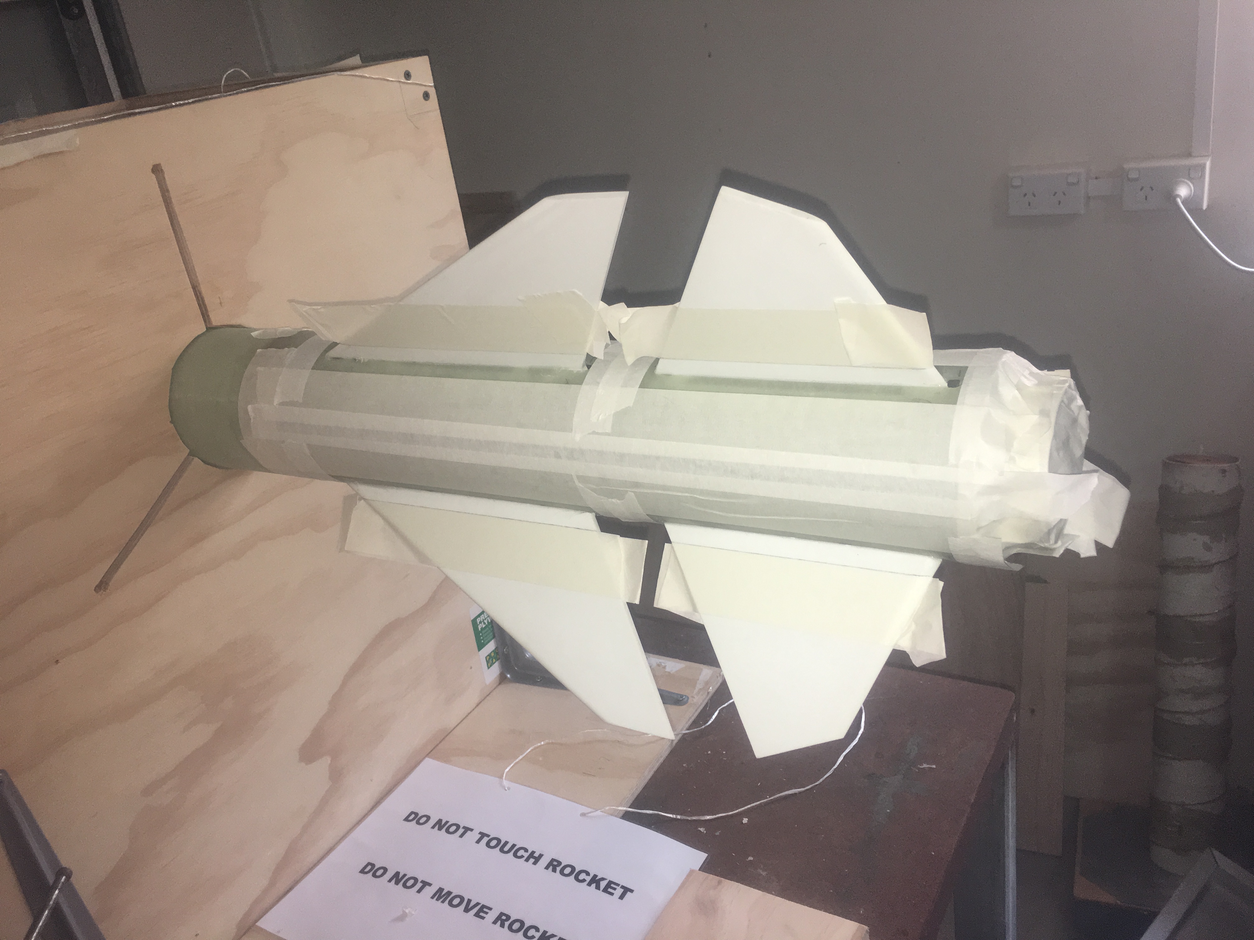
Keeping a rocket pointed up when launched from a balloon is not an easy feat. Countless hours of thought have been put into this and several ideas have been considered and then dismissed. Some of these ideas are presented below.

Have a rocket with Long Launch Rod

Can we use a launch rail, like we do on Earth?

No.

We need to first realise that while there is very little air at an altitude of 30km, there is still sufficient air to allow stabilisation using fins. This is provided we are travelling fast enough. The reduced air density means that the velocity required is substantially more then at sea level.  This means we would need a longer launch rail to ensure that the velocity is sufficiently great when it leaves the rail tip. Let’s consider the equations that give us lift.

Lift = Cl * density x Velocity ^2 * Area/2

Density of Air at sea level is 1.225 kg/m^3

Density of Air at 30km is  is 0.01841 kg/m^3

Let’s assume that 20ms-1 is the minimum velocity required at sea -level. With this we can estimate the minimum speed required at an altitude of 30km

velocity = sqrt(density-at-sea-level * velocity-at-sea-level^2/density-at-30km)

= 163ms-1

Let’s assume the rocket is accelerated at 10g  (98ms-2) up the rail.

v = a * t

t = 163/98 = 1.66seconds

s = 0.5 * 98 * 1.66^2 = 135 metres

This is clearly impractical. The launch rod would be very long, heavy and unwildy. We would need a massive balloon and someway to stabilise the rod. Then we would have the issue of the launch rod coming back to Earth. Totally out of the question!

Spin stabilisation

Another option considered was spin stabilisation, where by we attach rockets to the side to spin it up. This makes the rocket act like a spinning top. Simulations have been done to see how attaching two D-engines to a rocket, to see how fast it will get and how much the spin is affected when engines are slightly mis-aligned. Unfortunately. even with very small manufacturing tolerances there is sufficient wobble to cause issues. We tried to increase the Moment of Inertia in in some axes to reduce the amount of rotation in those directions, however this adds alot of extra weight which is extremely undesirable.  There is also the problem of how we suspend the rocket when we spin it up, or if we have to release the rocket and then spin up.

This solution is extremely unpractical and complictes the launch sequence considerably. There a lot more possible modes of failure.

We have decided against this option.

Thrust Guided Rocket

The idea here is that one can either:-

– Move the nozzle, which will adjust the thrust direction

or

Move some vanes that are downstream of the thrust that re-direct the thrust direction

With the solid engines, the former is inpractical. The nozzles are fixed.

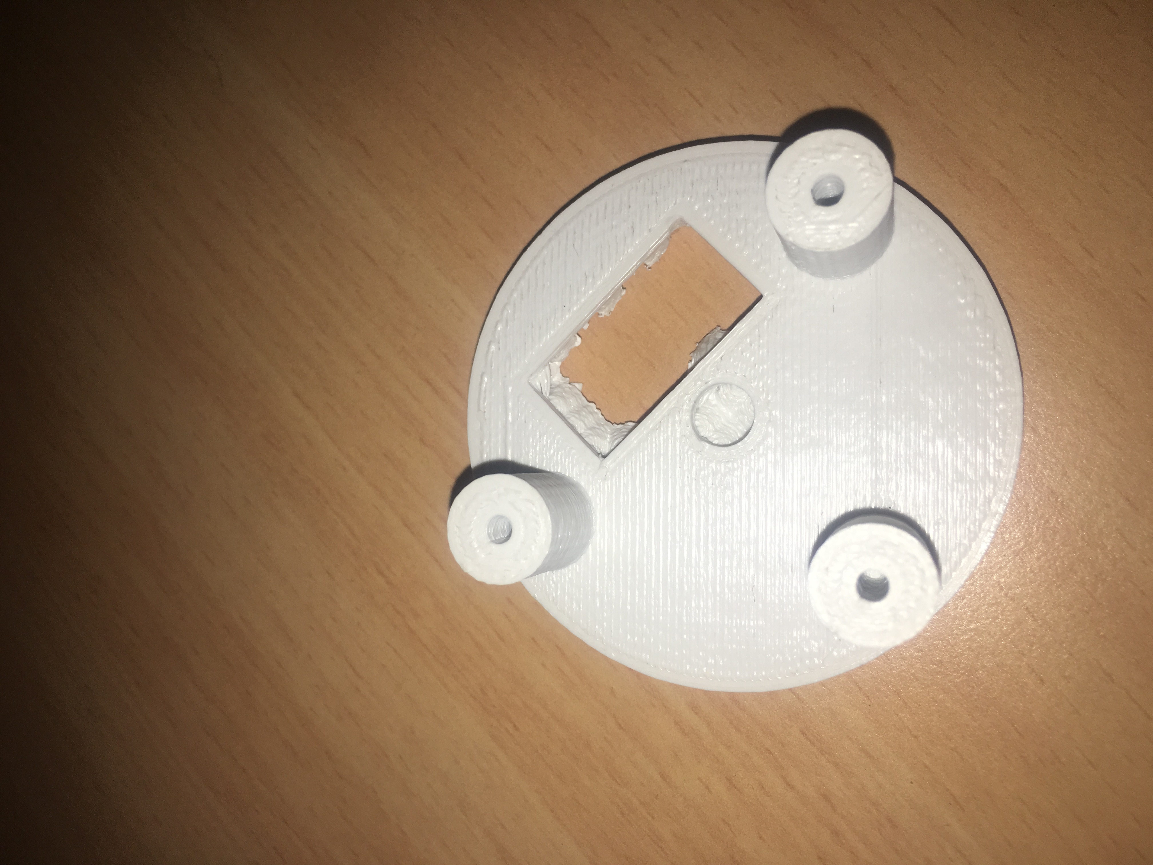
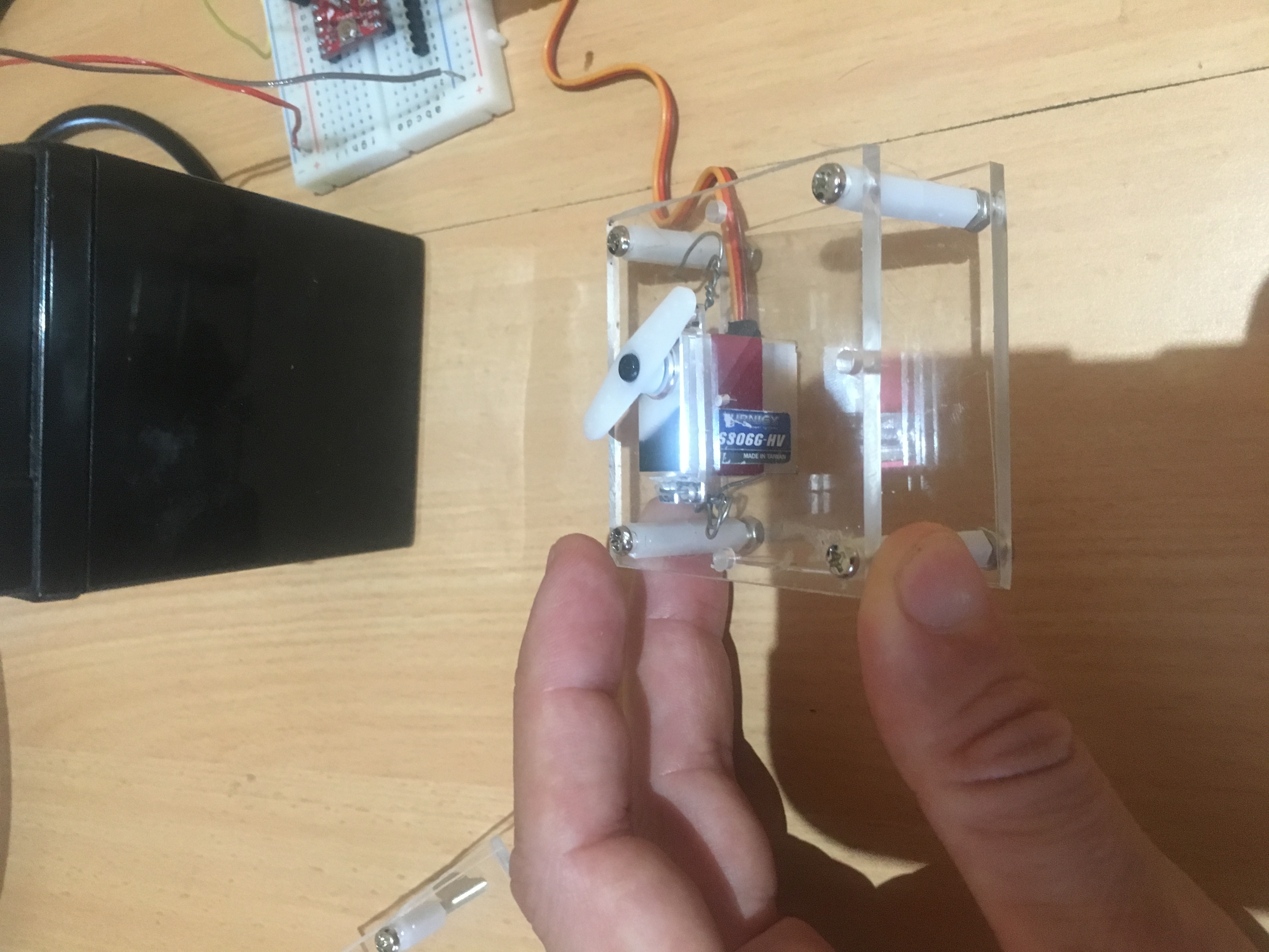
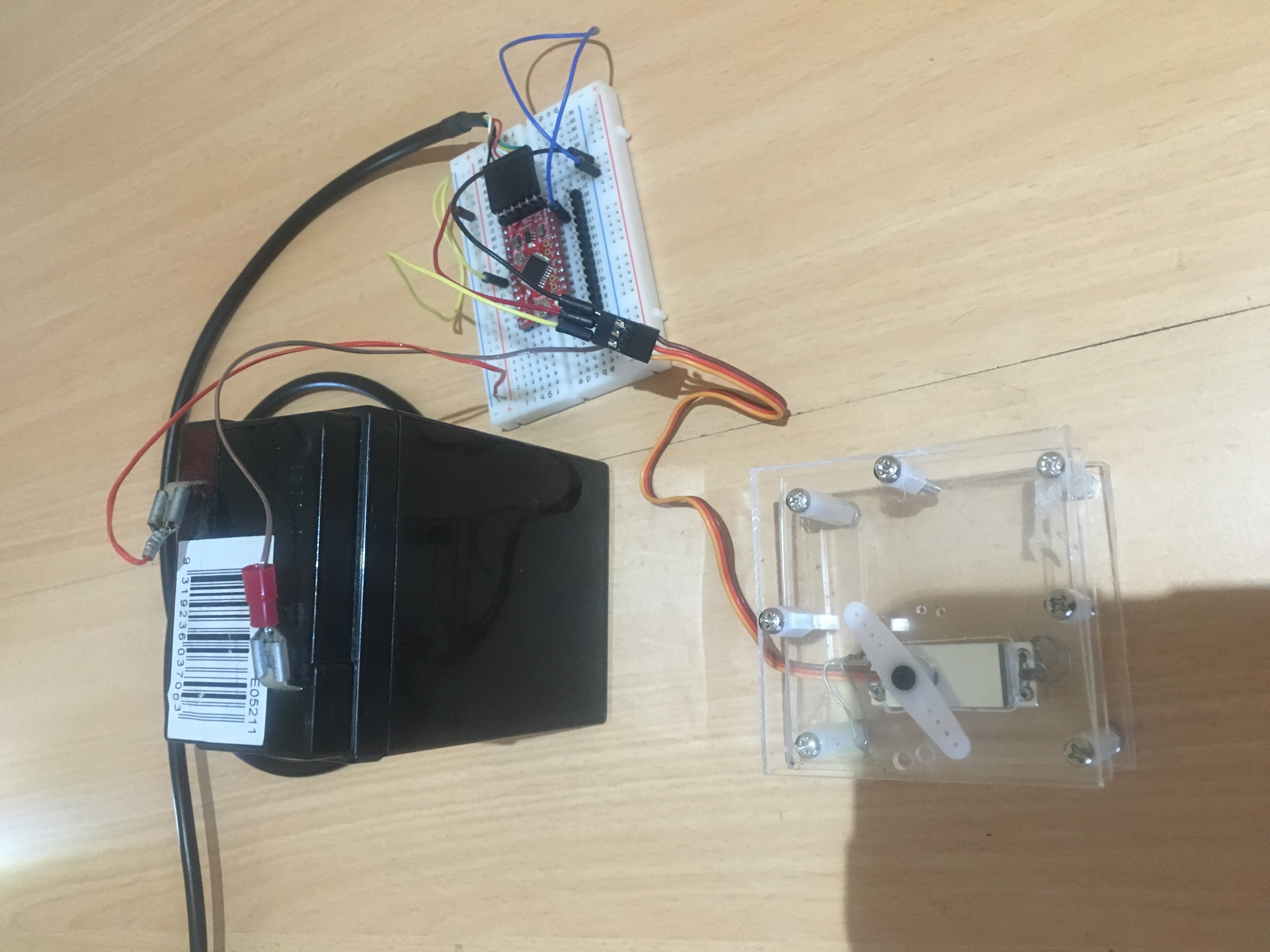
With the latter, the design is not simple, or easy to simple and some of the engineering required is not so simple. We would need some external actuators, ones that can provide a massive torque (to combat the force of the rocket thrust), while still keeping the rocket streamline, and at the same time using the limited ‘realestate’ at the bottom of the rocket. For the vanes, we would need special material that would not be destroyed by the thrust, be light and have a specific design to induce the right sort of adjustments.

We have decided against these two options.

Centre of Mass Guided Rocket

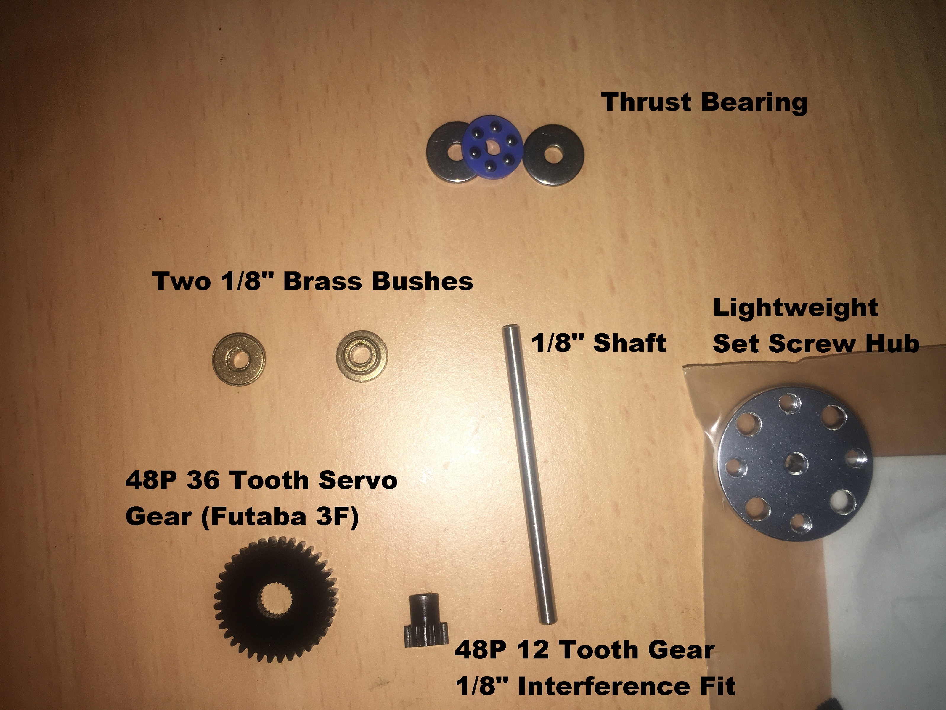
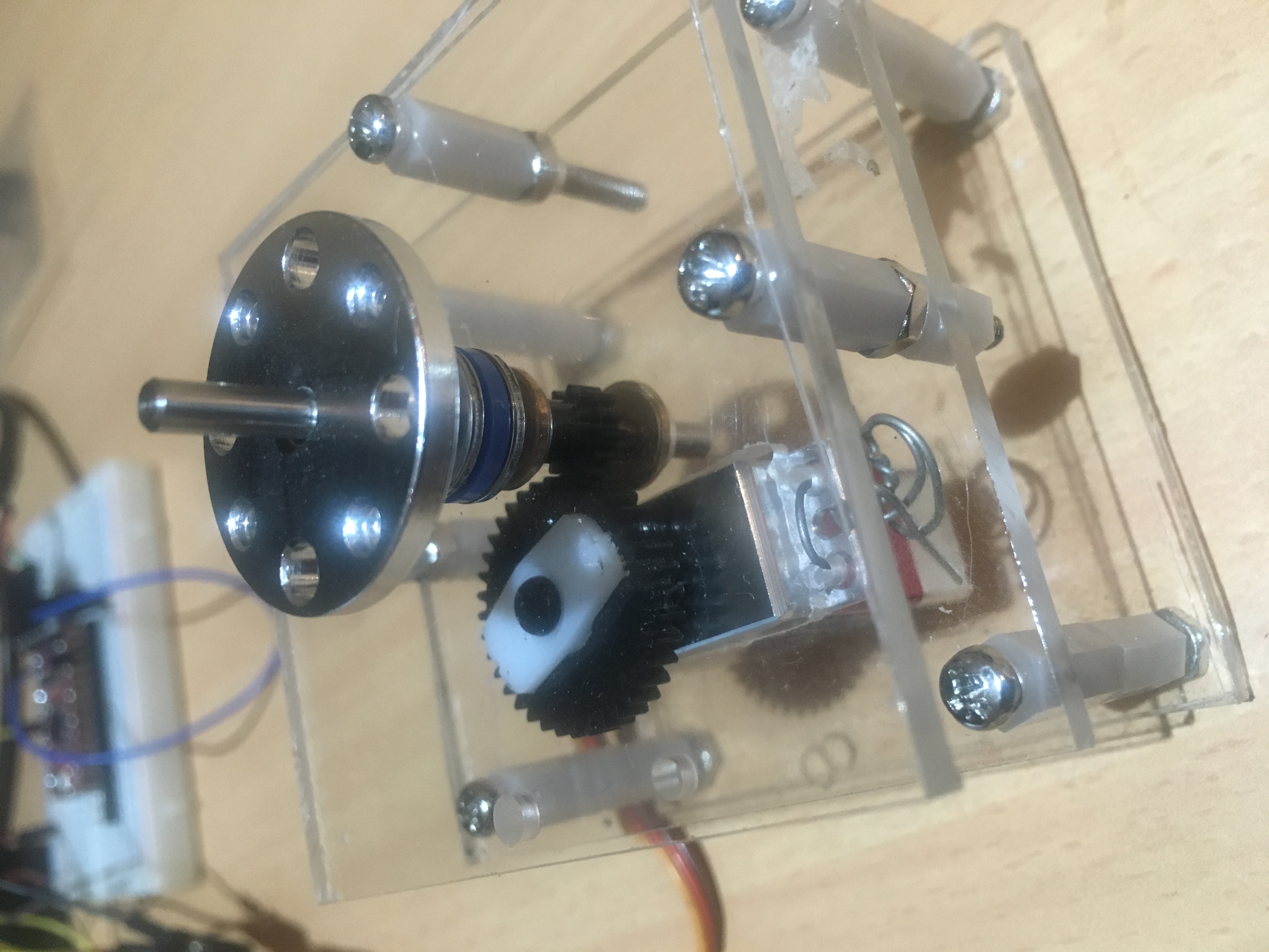
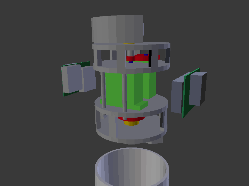
This is not a commonly used method, however, it has been mentioned a little in some of the rocketry literature on the Internet. The concept is that you adjust the Centre of Mass (moving it laterally) so that the thrust, in combination with this off-axis centre of Mass produces a resultant moment.

Imagine yourself standing up and someone pushing you backwards. You instinctively put your arms/hands outreached in front of you to try and move your Centre of Mass forward.

This method could work, but it would need to move masses quickly and efficiently without producing too much un-wanted disturbances to the rocket’s motion. The whole system would need to be relatively light, so as to not be a burden on the rocket.

Summary

The latter option seems the most likely to succeed. We have decided to put a more thought into such a solution. In particular, we decided it would abe a good idea to try and simulate such an engine.