I have recently received the PCB sensor board from the supplier and have started soldering components. A few pictures of this are shown below.
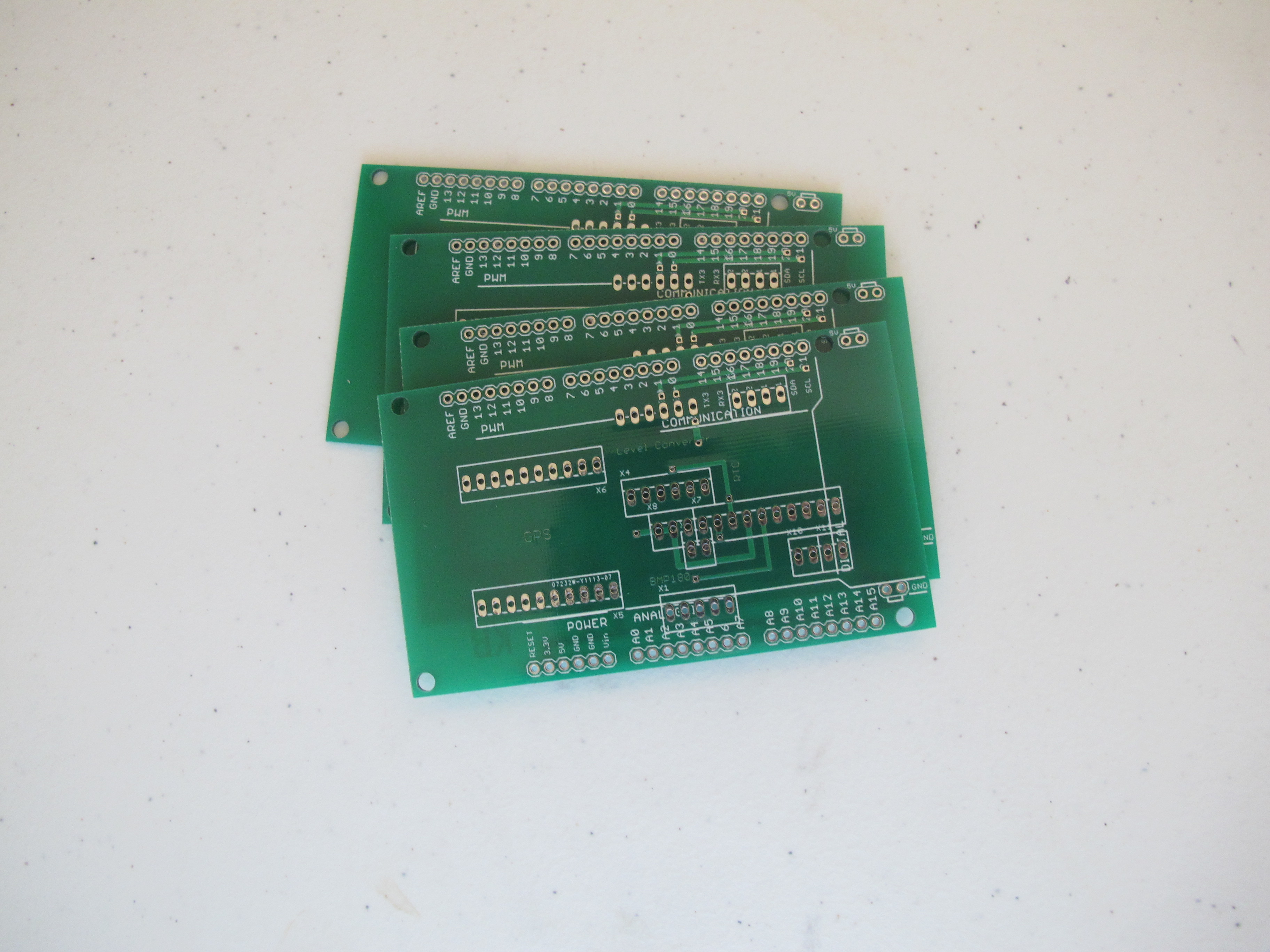
Bare PCB – Ready for soldering
Five boards were received in total. (These are “prototype” boards and the minimum order quantity is five). As you can see, the quality of these is exceptional….much better than anything I could do at home.
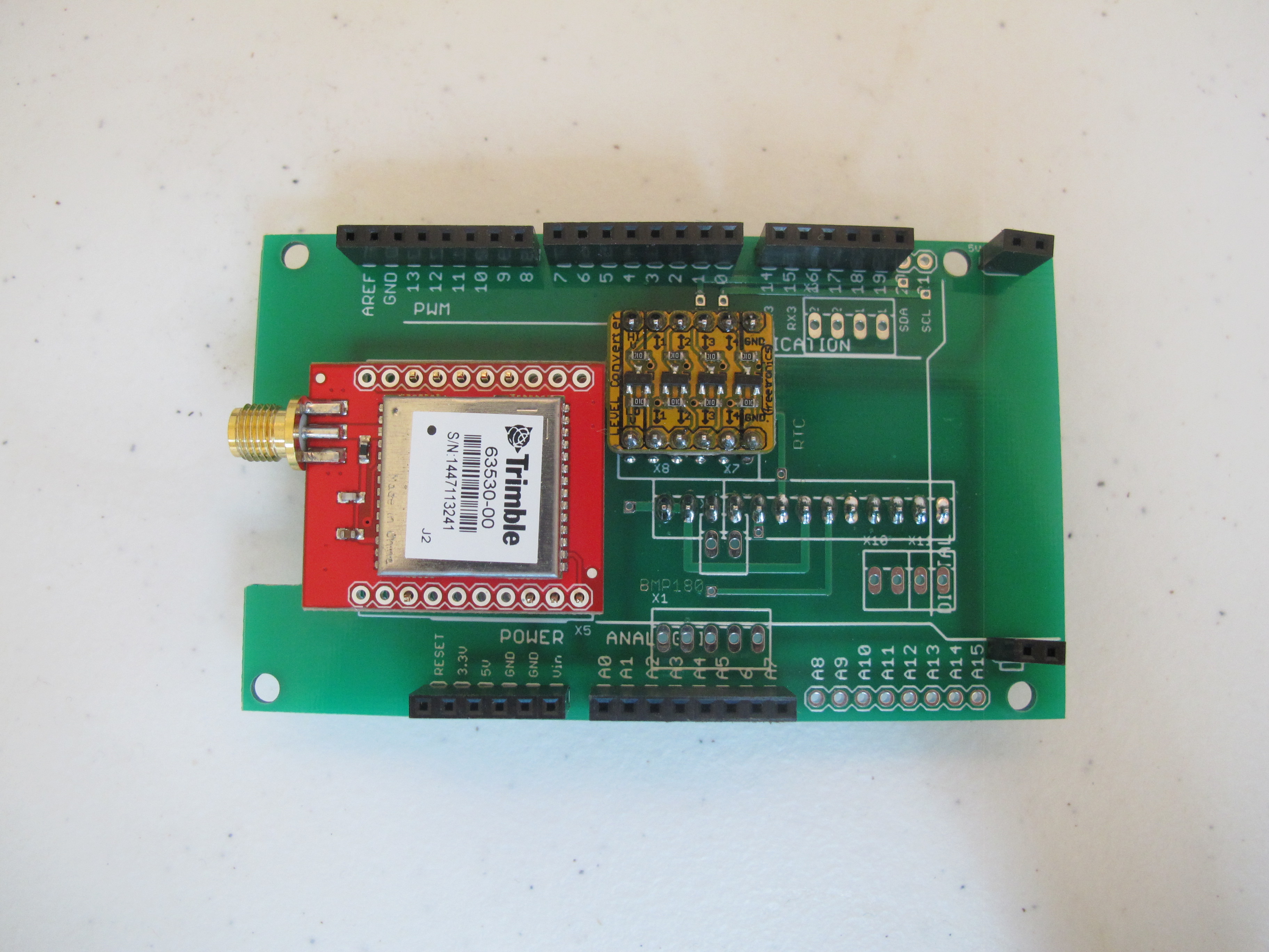
Top view: Some of breakout boards soldered on
Above is the GPS module (capable of operation up to 50km) and a Level converter. The Level converter is used by the GPS module and the IMU module. These two modules use 3.3 volts. The Arduino EtherMega operates at 5 volts.
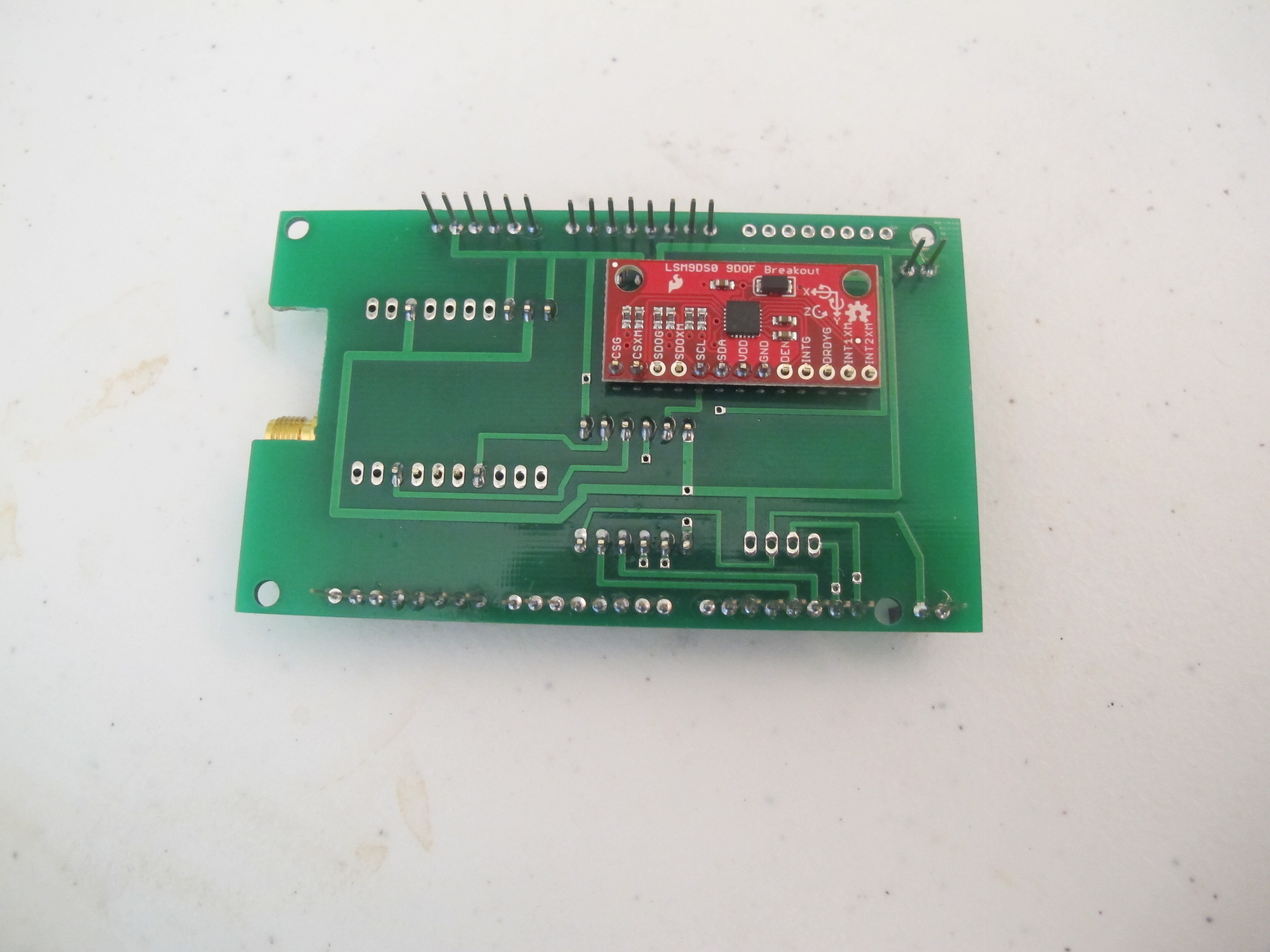
Bottom View: IMU soldered on
We put this on the bottom for space reasons. This just misses a few pins on the EtherMega by a few mm. So things are tight!
The REAL work beings soon…programming all these sensors. I expect the IMU to be particularly difficult.
We will start using this launch system for small Estee engines/igniters. So the first thing I wanted to do was model an Estes Igniter to find out how the battery would perform.
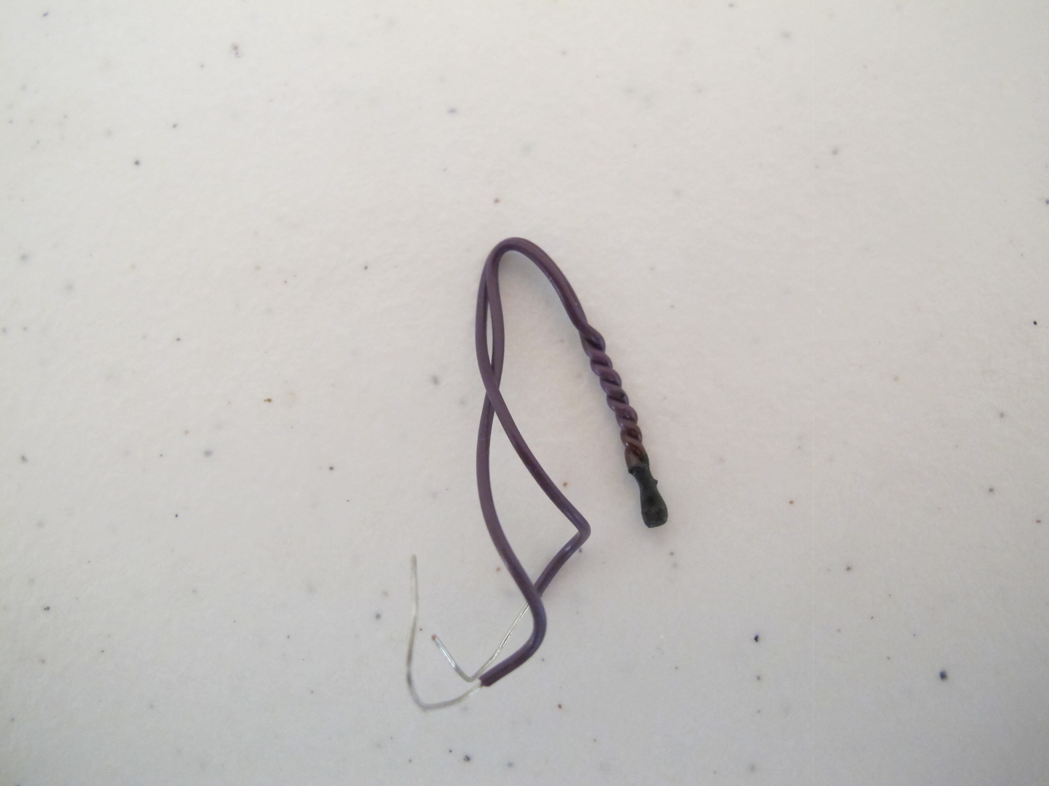
Below is a picture of a typical igniter.
Typical Estes Igniter
The resistance was measured to be approximately 3.5 ohms.
If we assume resistance of battery and wires combined is approximately 0.5 ohms, we are looking at a total resistance of ~4 ohms. With an igniter battry of 12 volts, we are then looking at a current of approximately 3 Amps. This is well below the maxiumum current the relays can take (5Amps) and the wiress, connectors should be able to handle this current.
NOTE: When we get the relay board made to replace the current prototype, we will get 2Oz Copper board produced…which should double the current it can handle.
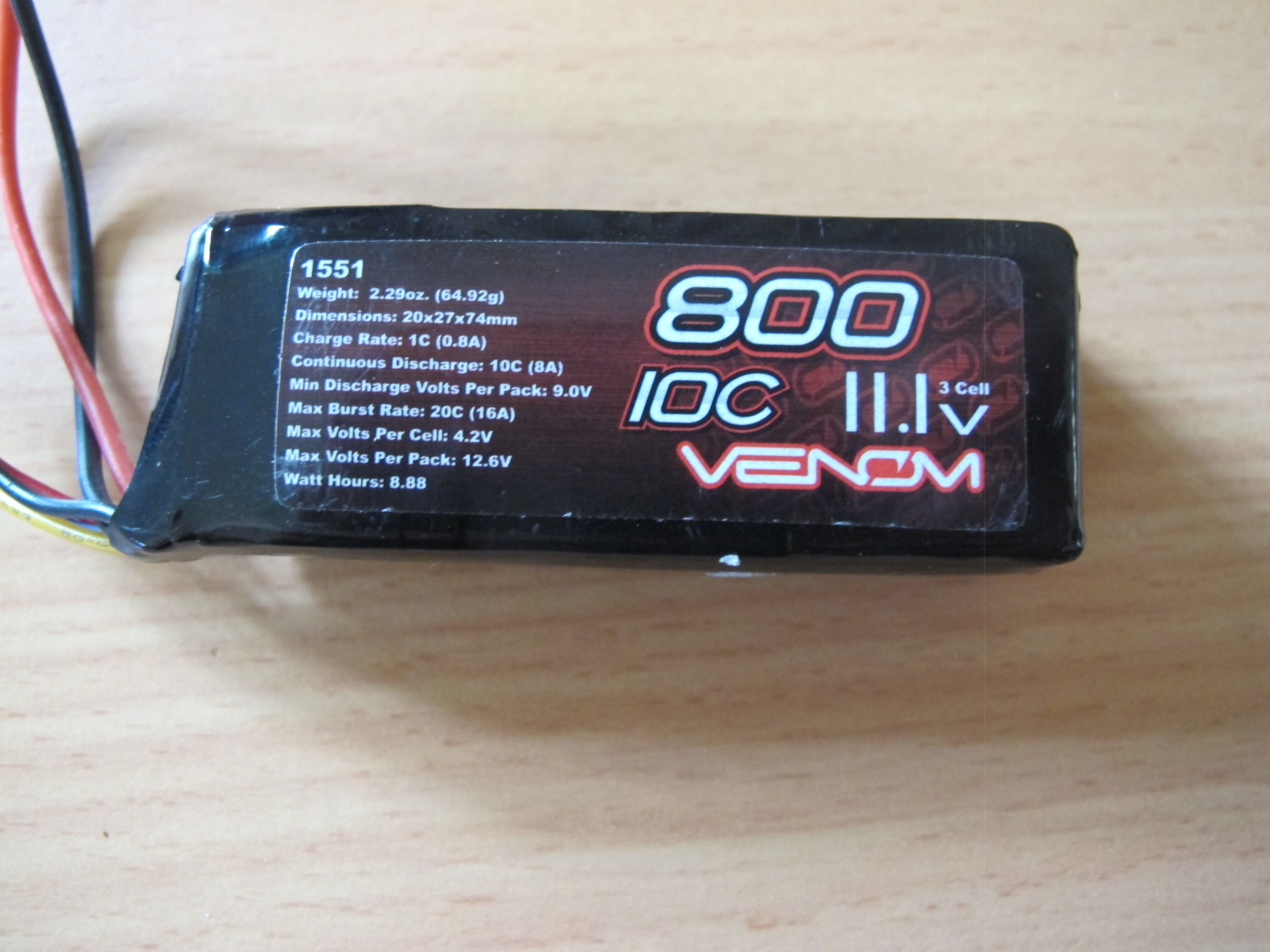
We really wanted to measure the resistance of the battery and the power dissapated by the battery. We do this because want to be sure the battery is not under too much ‘stress’. We know it _should_ be able to handle this current draw. It is rated as 10c (8Amp) continuous dis-charge and Max Burst ate of 20C (16Amp) so it should have absolutely no problems.
The Battery we will use to ignite rocket igniters.
Nethertheless, we wish to understand its operation completely so that we are sure we don’t ignite the battery instead!
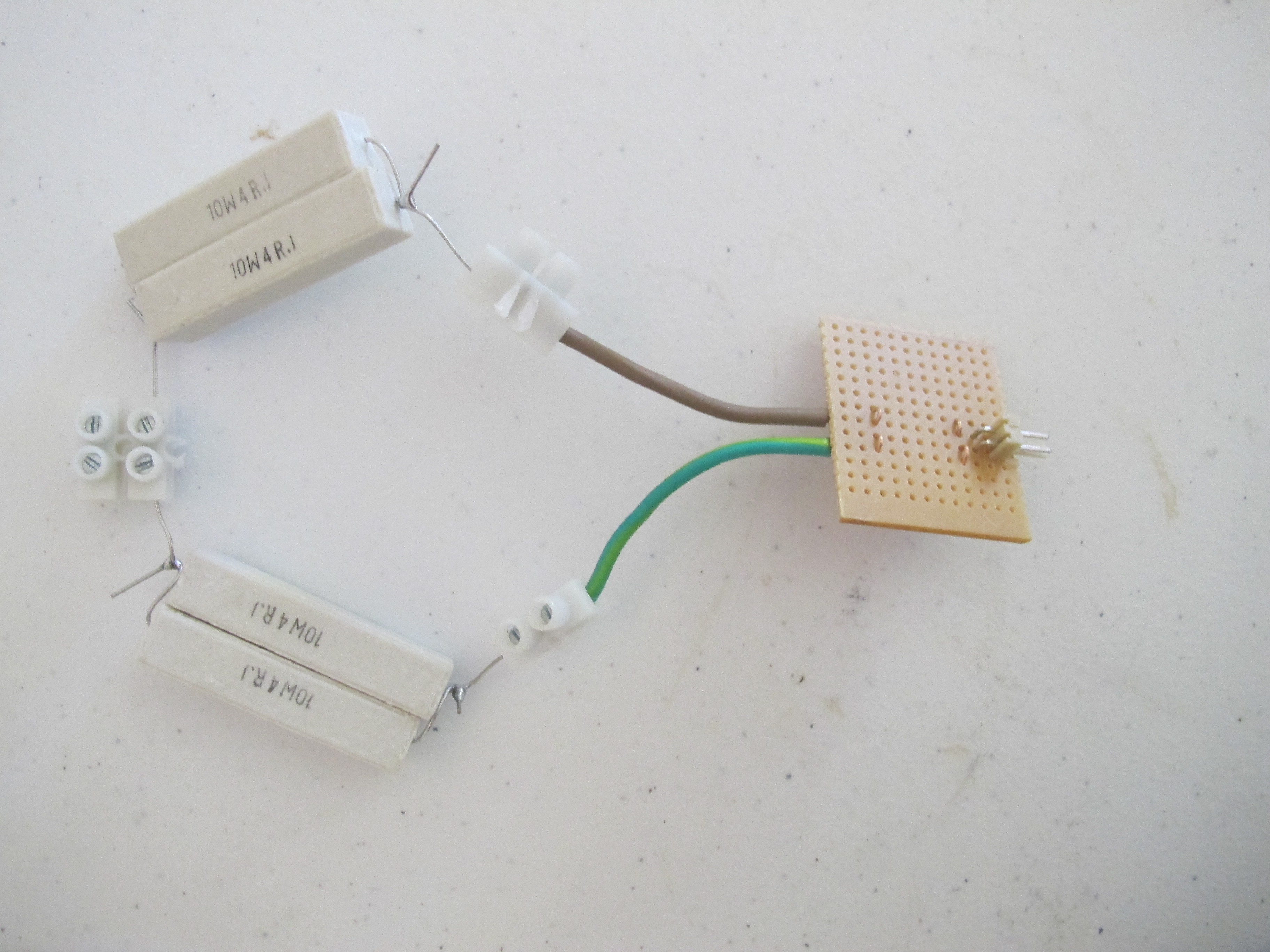
We decided to perform a small experiment to calculate the internal resistance when a current of 3Amps flows. Below is a picture of the test load.
Resistance load
Each resistor is a 10Watt resistor with a restance of 4 Ohms.
This means the total resistance of the load is 4 Ohms and it can dissapate a maximum of 40Watts (without exceeding specification of resistors).
We measure the open-circuit resistance of the battery and the closed-circuit resistance of the battery (when connected to the load). The values we got were:-
Vo = 12.15 V
Vc = 11.67 V
We then computed the internal resistance to be roughly 0.14ohms
So the power dissipated through the battery at a rate as shown below:-
P = VI = (12.15 – 11.67) ^2 / 0.14 = 1.6Watts
The power dissipated through the igniter is:-
P = VI = 11.67 ^2 / 3.5 = 38.9 Watts.
This is what we hoped for and expected. The igniter because of its much lesser mass should heat up significantly, exceedingly faster then the battery and ignite the pyrogen.
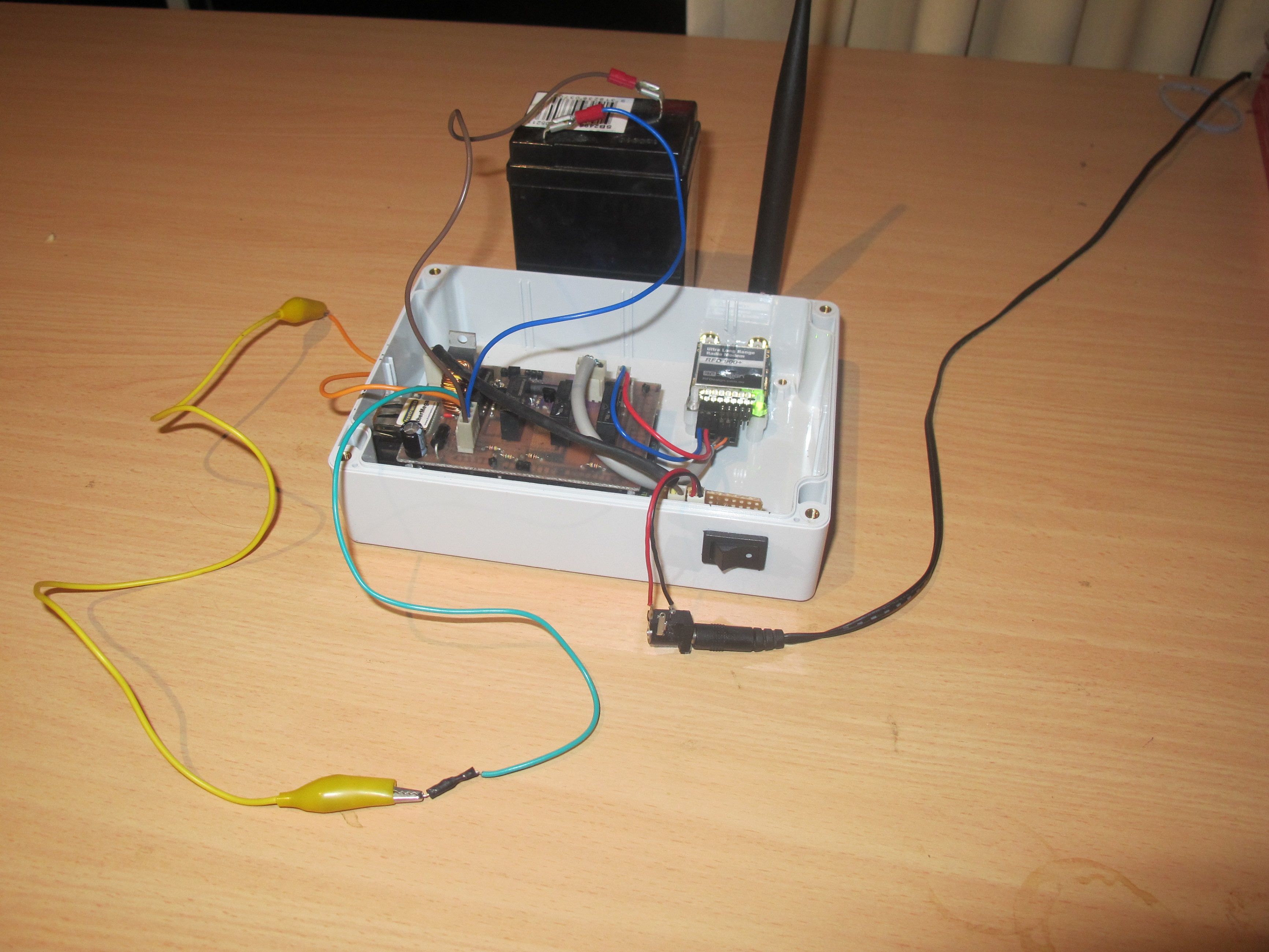
A lot of work has been done to date. This is the reason for very little activity on the Blog. Below are some some high level pictures.
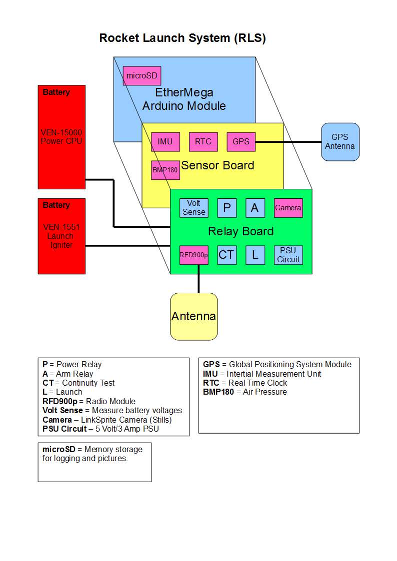
Rocket Launch System Components
The above picture is supposed to show that there are 2 boards stacked on top of the EtherMega Arduino board. The sensor board is a WIP. There is a huge amount of work still to do. The good thing is that the Sensor board is not required to use this purely as a wireless rocket launch system.
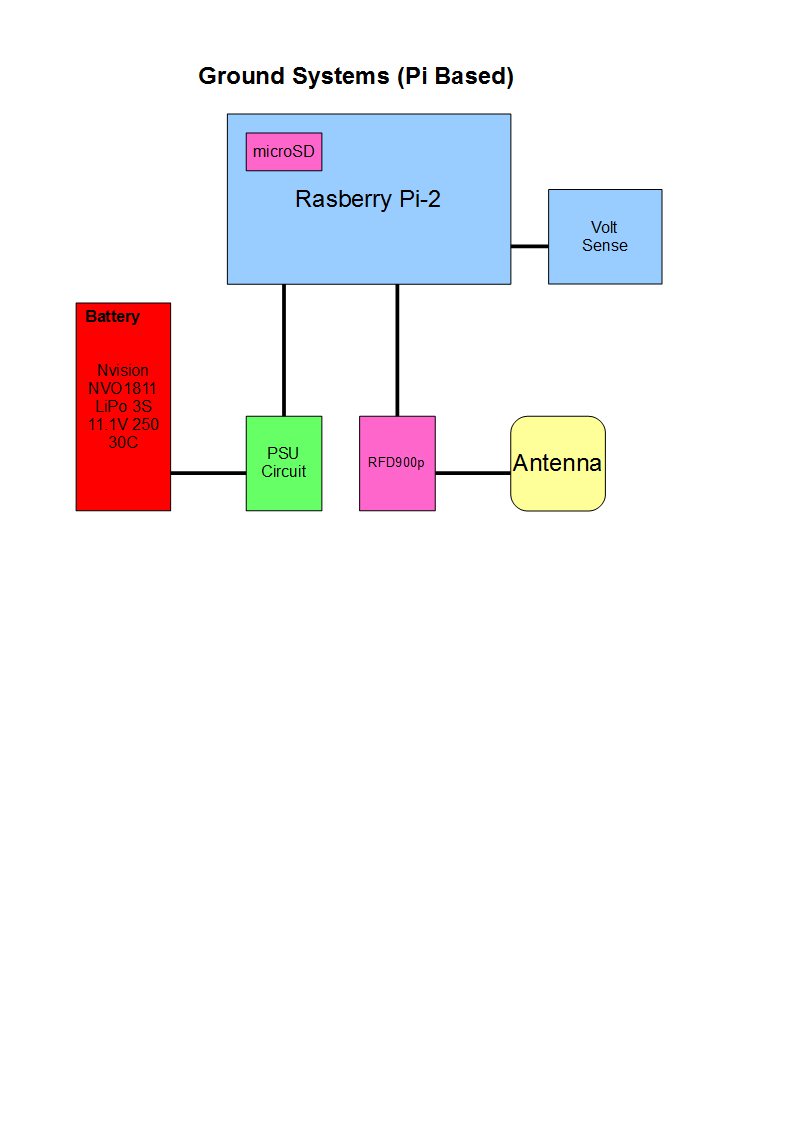
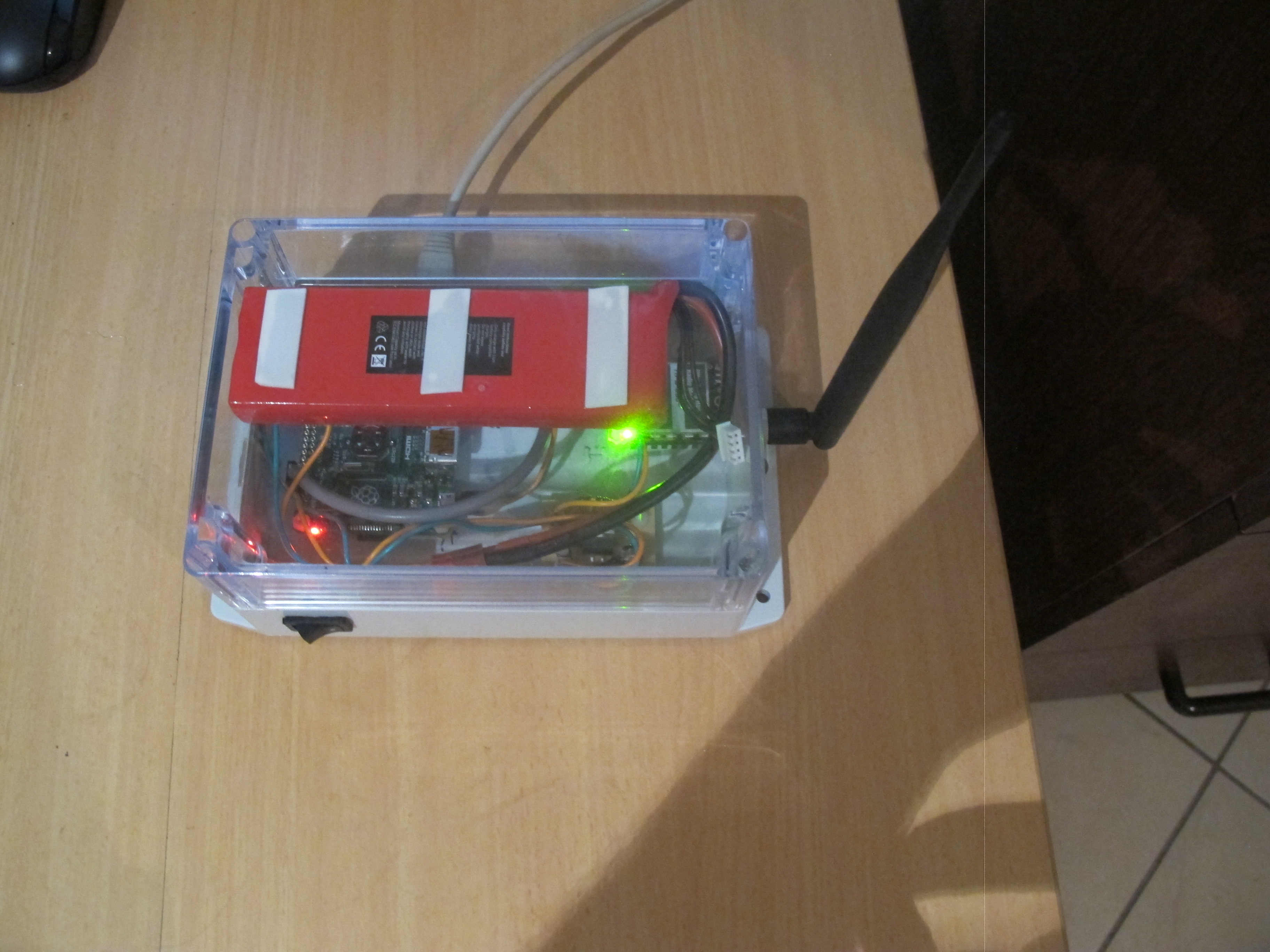
Ground Systems Components
Below are some pictures of it in action.
Rocket Launch System. Still a WIP
This is a picture taken prior to the install of the new batteries
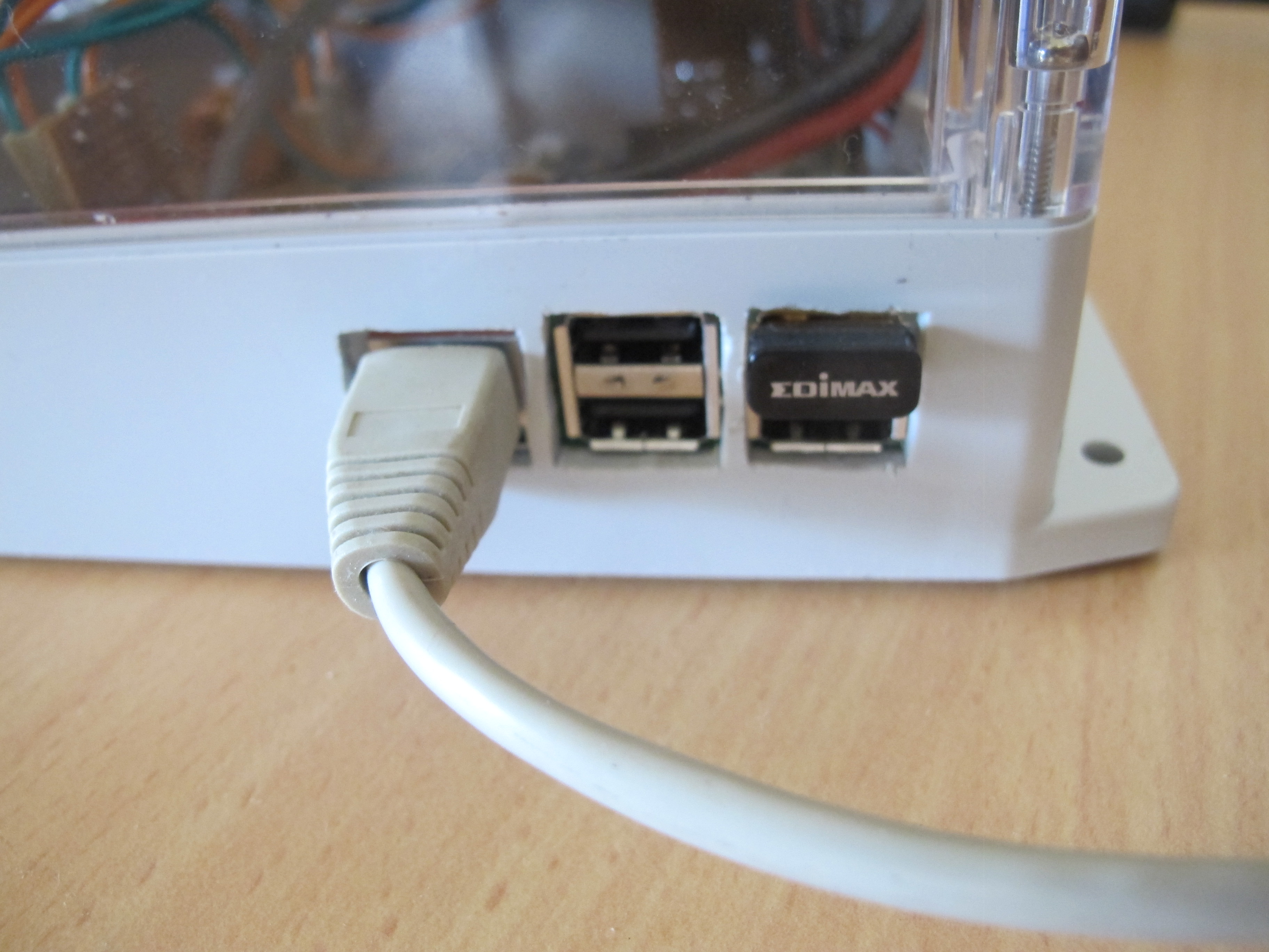
Ground Station – A WIP.
We can plug an Ethernet connection in to allow easy putty access into the Rasberry Pi to do our development. It is not required in normal operation. Below is a picture taken of back showing the Wireless dongle.
Showing wireless dongle
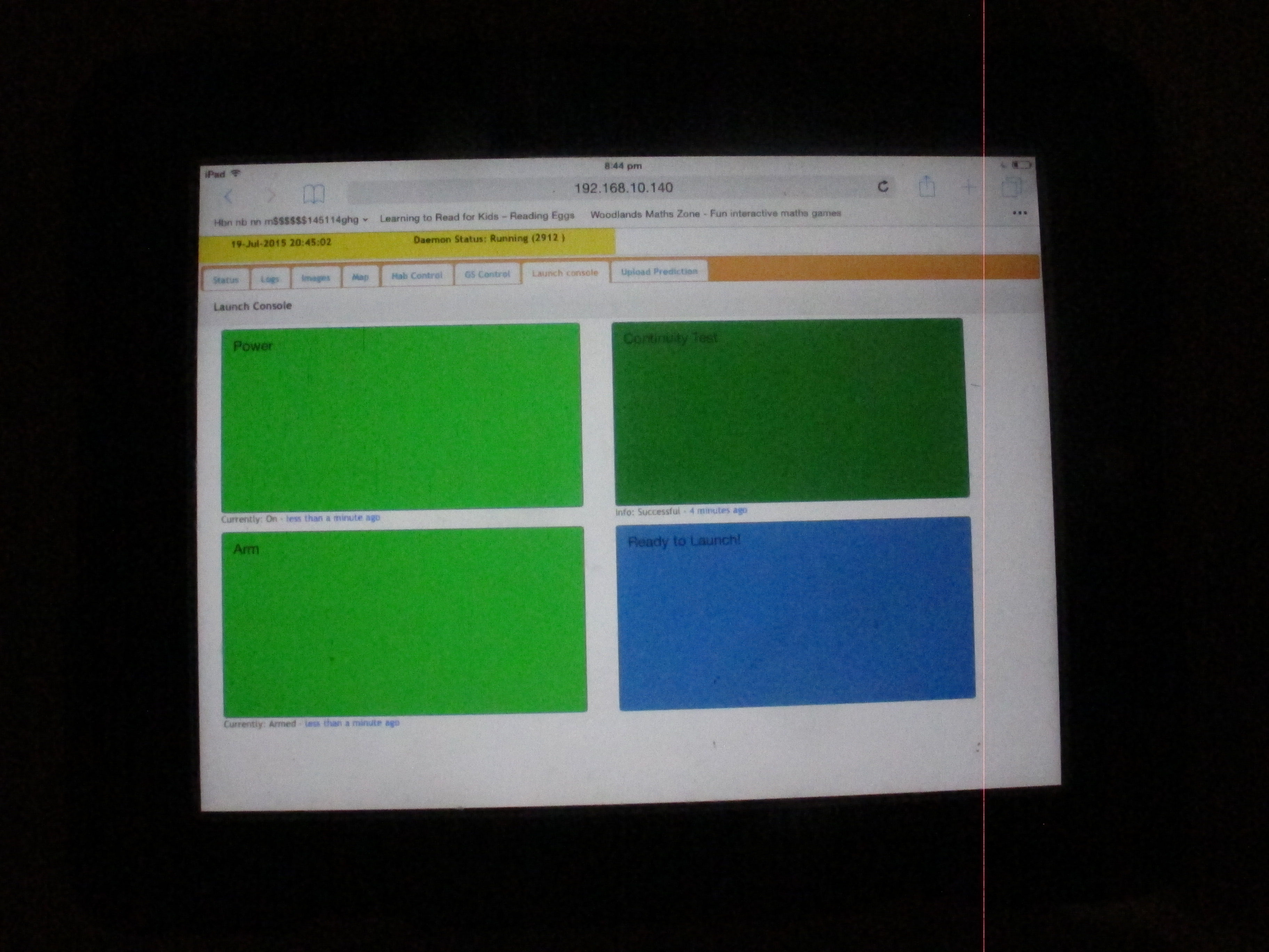
The two units can now commnicate across wireless link (900MHZ) while the ground station can communicate with an iPad, iPhone or other wireless device. Example of launch console screen is shown below.