Avionics – QA – Improvements

The success of the flight is reliant upon the ejection charges separate the components and this this all depends upon the integrity of the Avionics installation.

For this reason, we review the Avionics bay to ensure that risks are identified and addressed.  Some of these counter measures are shown in previous posts and no mention was made of how we arrived at the design here.  We do this here.

Risks with Counter Measures

Switch Terminals

We were going to solder tips of wire and screw them into the terminals of the lever switch. When screwing them in, it tends to twist the entire wire around. This is probably “fine” but I can imagine that there is stress on the wire. The washer/screw should remain in place, but it is far from ideal.

So, what I did was get some very thin copper plate and cut out a small strip, 5mm x 10mm. Then I drilled a 3mm hole at one end. I sanded down the copper pieces of both sides and on curled one end (not the end with the hole) a little. Then I soldered a wire to the copper, leaving a small gap at the end with the hole (so I don’t add excessive thickness). At the other end, (the curled end), I applied 5 minute epoxy to the wire/insulation. This provides a very strong connector which won’t turn around when being attached to the switch and minimal strain is put on the wire strands! The copper is a great conductor and is very easy to solder to. Copper can also be bent to whatever shape is required.

Below is a picture as it might be hard to visualize it from the description above.

Copper connector attached to switch

The curl is intentional. It reduces chance of wire rubbing against sharp edge.

Screws

Screws can rattle undone, so I applied LocTite equivalent to all screws. This includes:-

  • Bulkhead powder wells (PVC caps)
  • Bulkhead terminal blocks
  • Raven 3 PCB screws
  • Screw holding the switch right-angle
  • Screws holding the 3 x 2 black terminal block

Glue to some components

A lot of the components that are attached only have one screw. They are tightened a lot, but there is always the risk they could loosen/rotate. To reduce the chance of this, I applied a few drops of CA glue to them. The parts that had this done were:-

  • Bulkhead powder wells (PVC caps)
  • Bulkhead terminal blocks
  • MicroSwitch right-angle aluminium piece

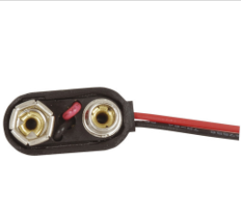
Nine Volt battery Clip

I was concerned that the 9 volt battery clip was not of sufficiently strong construction and the clip I used was recycled from another project. So what I did was purchase a replacement one from Jaycar.

Tough 9-volt battery clip

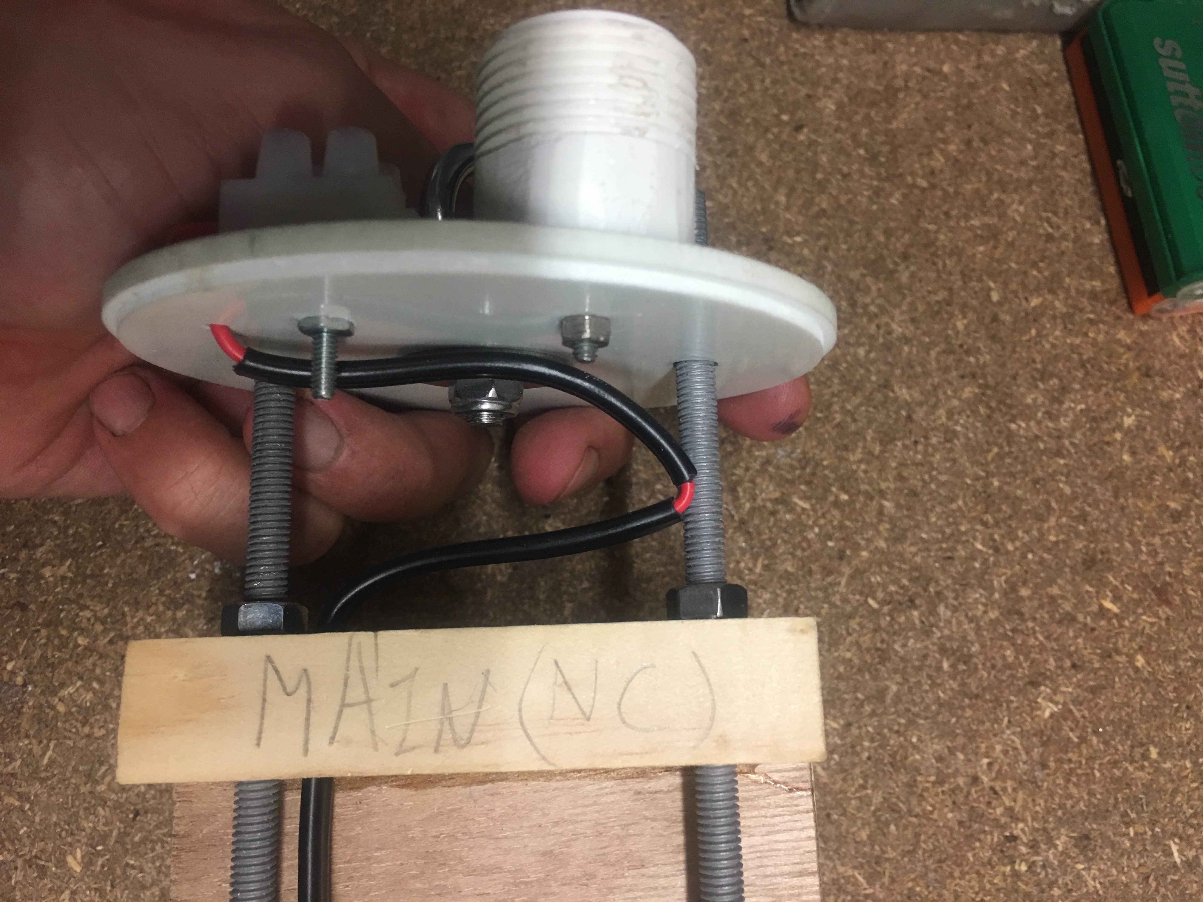
I was also concerned about the red/black wires getting into places they shouldn’t so I :-

  1. Cut the black wire to a length that meant it couldn’t possibly be a problem
  2. Applied small drops of CA glue to the red wire where I wanted it to rest, just to encourage it to stay there. It may come of in flight, but its insignificant weight means it should be okay.
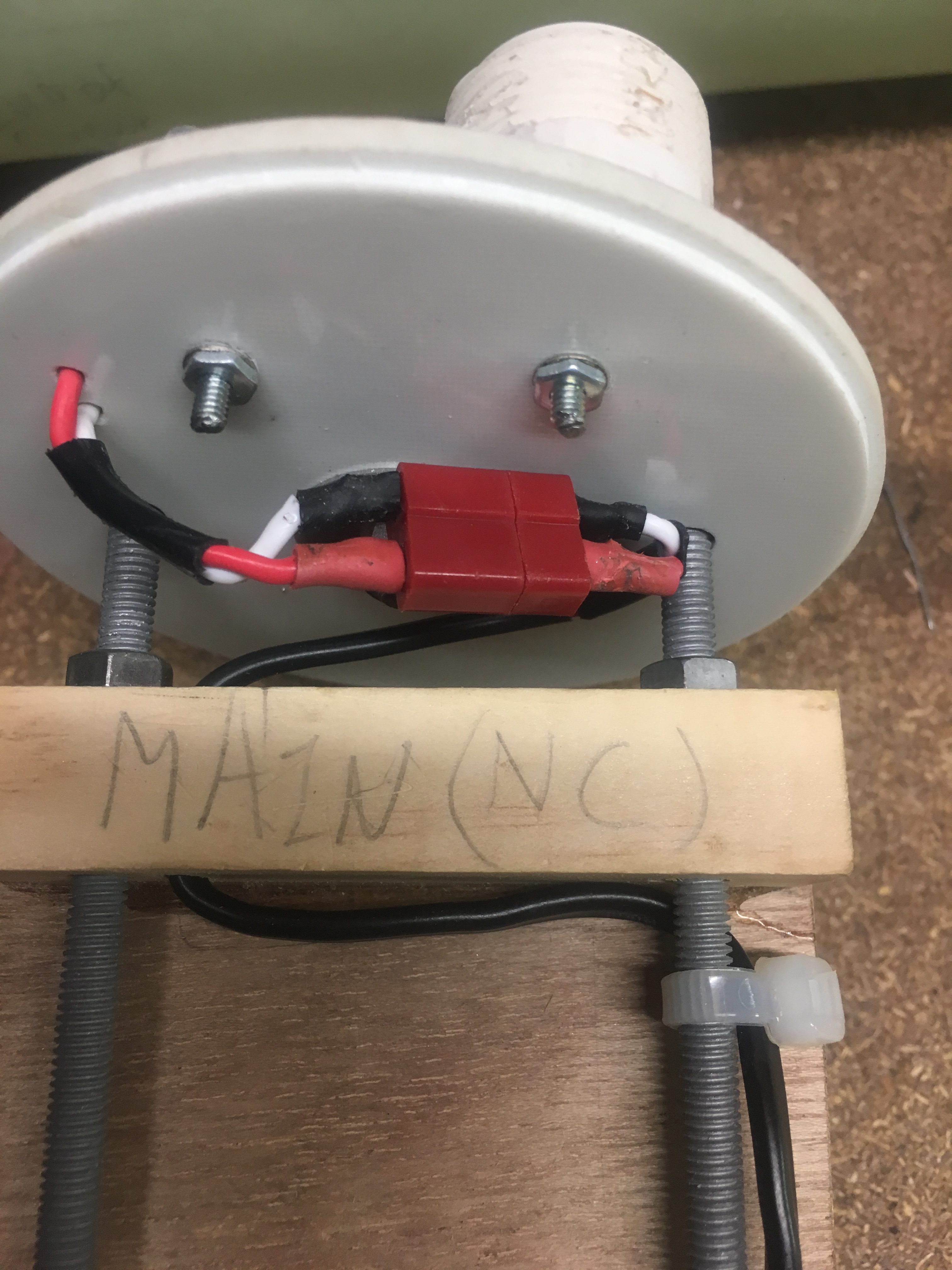
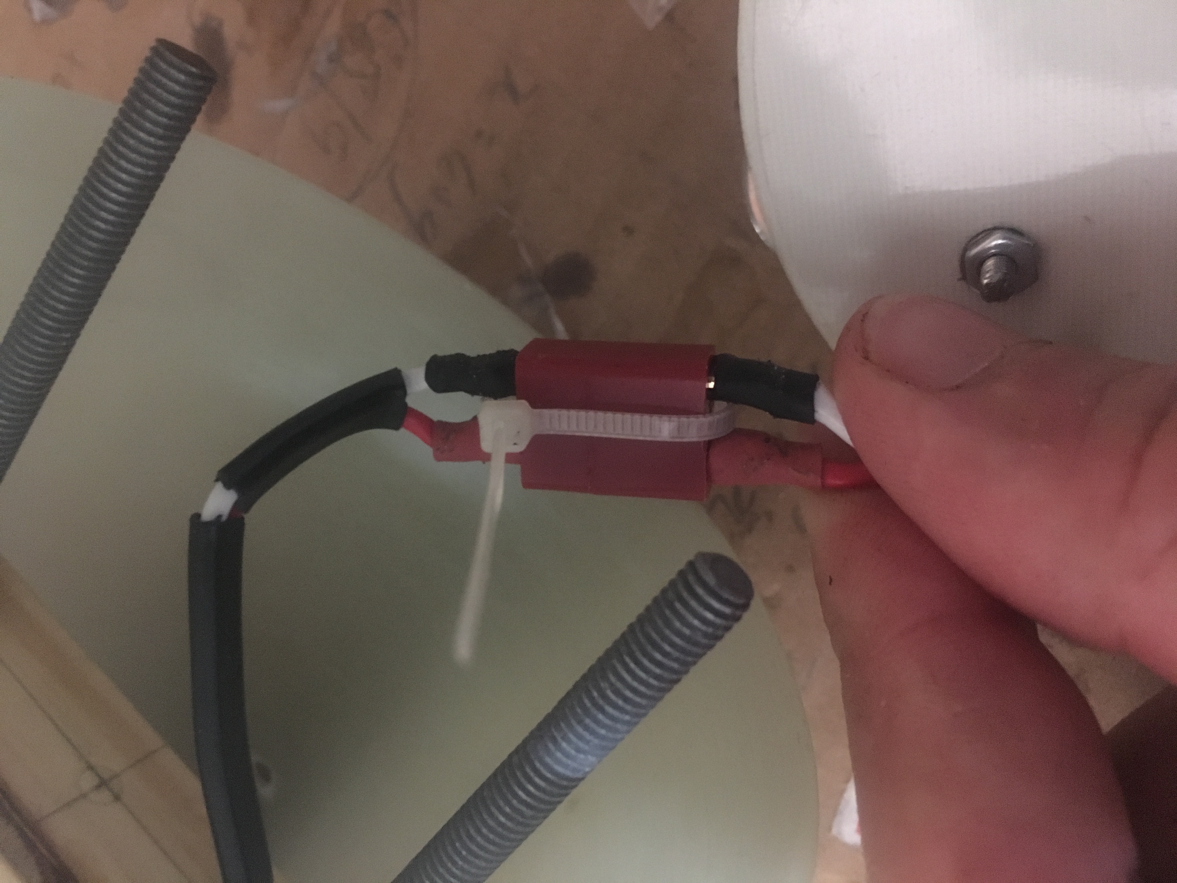
The Dean-Plug

I wanted to ensure that Dean-Plug would not separate in flight. So I will install a small cable tie as shown below.

Cable-tie to keep dean-plug attached.


Wires into Raven3

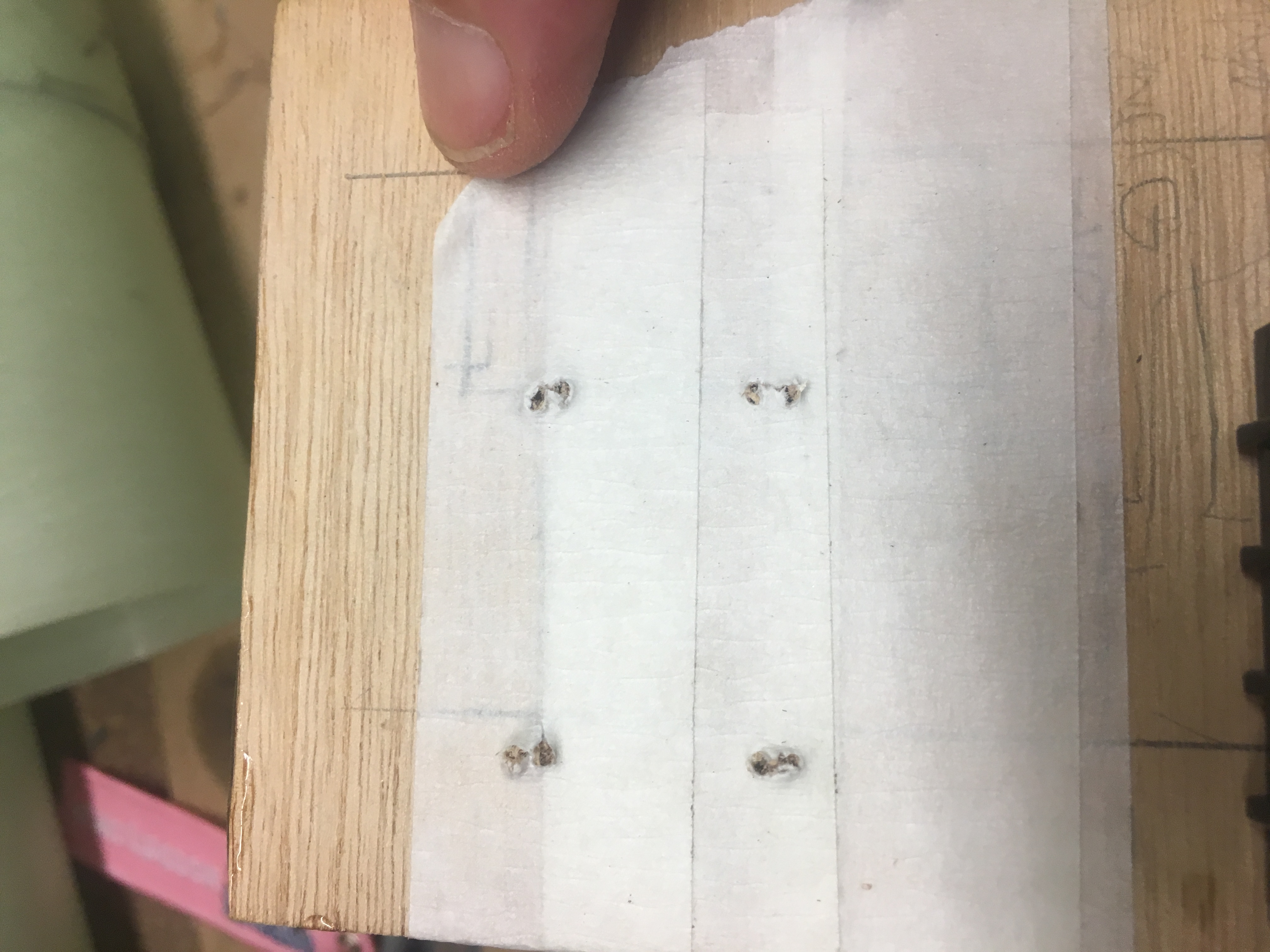
I removed a little more insulation then i should have on some of the wires that are screwed into the Terminal block on the Raven 3. As a consequences, some of the wire was visible. While it is extremely unlikely that we could have some short, I decided to cut the wire a little, to reduce the amount of bare wire showing. See the picture below.

Photo showing bare wire showing.

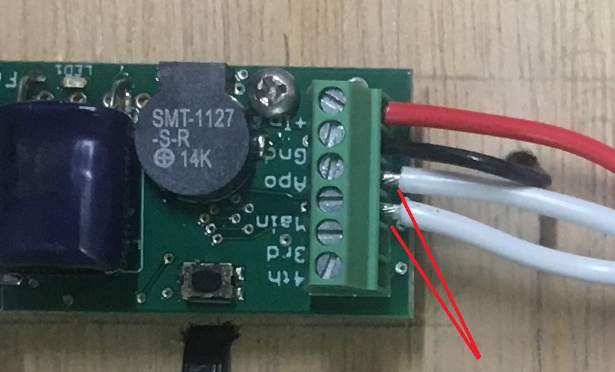
It is also about taking pride in the work that I do; keeping it look good as well.


SuperCap on Raven3

It is recommended that the SuperCap be glued down if the rocket is going experience high-G flights. My first flight of this rocket will not involve high-G’s, but subsequent flights may. Following instructions, I decided to apply a drop of Epoxy under the capacitor.


The Avonics Bay – Installing the Electronics

I received the Raven3 Altimeter, Shockcord, parachute bags and the RBF tag and so thought I should start installing the Avonics bay Electronics.

The thought process

Normally,  one would expect that installing the electronics would be easy to do.  Just mount battery,  mount the Altimer, run some wires using cable ties, etc. But, more thought is involved in terms of placement. So I spent much time playing around with places to put the components.

I also had to decide a few other things:-

  1. How to construct the switch
  2. What type of battery to use
  3. The type of wire to use.

Switch

I decided to use a 10amp/250volt (AC)  switch. This _should_ do the job, though I get the feeling that with DC voltages, it might not be as robust. That is okay, I will many tests to see how it fairs with setting off igniters.

Battery

I was going to use a LiPO battery, because they are so much more efficient than standard batteries. However I realised a LiPo does pose other issues. One being that I might need two LiPo batteries to supply required current and that I might have shipping/logistic issues with LiPo. So in the end, I decided to go for a 9 volt battery. I’ll probably use a Li/Mn Energizer battery (one of the blue ones).

Again, tests will tell me if my decision was a good one.

Wire

for the igniter wire, I choose wire that is rated 7.5Amps. This should be more then ample. I don’t expect it to pass this much current before the igniter does its job. I got twin wire (in a sheath). It makes for a neater job. This wire also fits inside the terminal block on the Raven 3 board. Very important!

Junction point

I wanted a 4 way splitter to allow the distribution of +9 volts to the igniters and the Raven 3. So I purchased 3×2 and used copper hook-up wire to link all three together.

Dean-Plug

I need to be able to disconnect the bulk-head without taking wire out of the terminal blocks mounted to the Bulkheads. I did this by installing a Dean-Plug. Then I’ll use a small cable-tie to ensure they don’t separate in flight.


Heat-Shrink

I wanted to guard against wires rubbing against the threaded rods and I wanted to reduce chance of shorts, so i employed heat-shrink over the rods. I didn’t bother to “shrink it” with heat, because I might want to remove them easily.


Here are some pictures of the Avionics bay

Altimeter side of the payload bay.
Battery side of the Avionics bay.
Dean Plug installed at Main Parachute end.

Using masking tape to improve quality of holes when drilling through plywood.

Using masking tape to improve quality of holes when drilling through plywood.

Sizing up Dean-Plug for Main parachute end.
Switch mounted to aluminium Right-Angle
Main Parachute Wiring. Notice removal of some insulation to encourage bending of electrical cable.


Here are a list of things that I did to ensure a good build:-

  • Put in Witness marks so I know how to assemble it back together, with everything in the right spot. This is very important for the Remove Before Flight Pin. We needed to align the Vent hole with the Pin hole.
  • The switch mounted to the Aluminium bracket is on a slight angle. This is done this way so that we have optimum lever position when pin is inserted. i.e. it is undeniably in the closed position
  • We have rounded the end of the pin – hemispherical. This is to make pin/switch work better
  • While the hole in the wood that the pin is pushed through is big enough for a loose fit, this hole was NOT done all the way. Part of the hole is a close fit, which means that the pin doesn’t just fall out. This is very important. We don’t want the system to be accidentally armed
  • With all screw/nuts, I used Loctite equivalent to ensure screws don’t accidentally come off!
  • For the 9 volt battery, I am using a higher quality clip, to reduce chance of failure here
  • For screw on to the switch, I’ve made up my own eye connectors using copper. I’ve bent the far end down a little to reduce chance of wire/insulation being ruined. I’ve applied plenty of solder to ensure a good connection and I’ve finished it off with some araldite to ensure that the soldered connection isn’t taking physical load.