Fin Work Preparations

The next step is to profile the fins and to score/sand the roots and tangs. Some important decisions to make are:-

  • How to evenly sand the surface of the fins (so it is symmetrical)
  • What profile is required – at leading edge and trailing edge.
  • How to score the fins

We concentrate on the first two here.

Fin Symmetry

When I examined the fins, the first thing I noted was that the chamfer in them is not symmetrical to begin with. This is unfortunate, but I’m just going to have to work with it.

Shaded view shows size of chamfer. Notice different width.


Notice the lack of symmetry.

Well, that is something we will need to work with. I had a vision of a semi-circle shaped leading edge, but this is probably not possible now. Will probably make them parabolic, or elliptical in shape.


The tools to sand down the fins

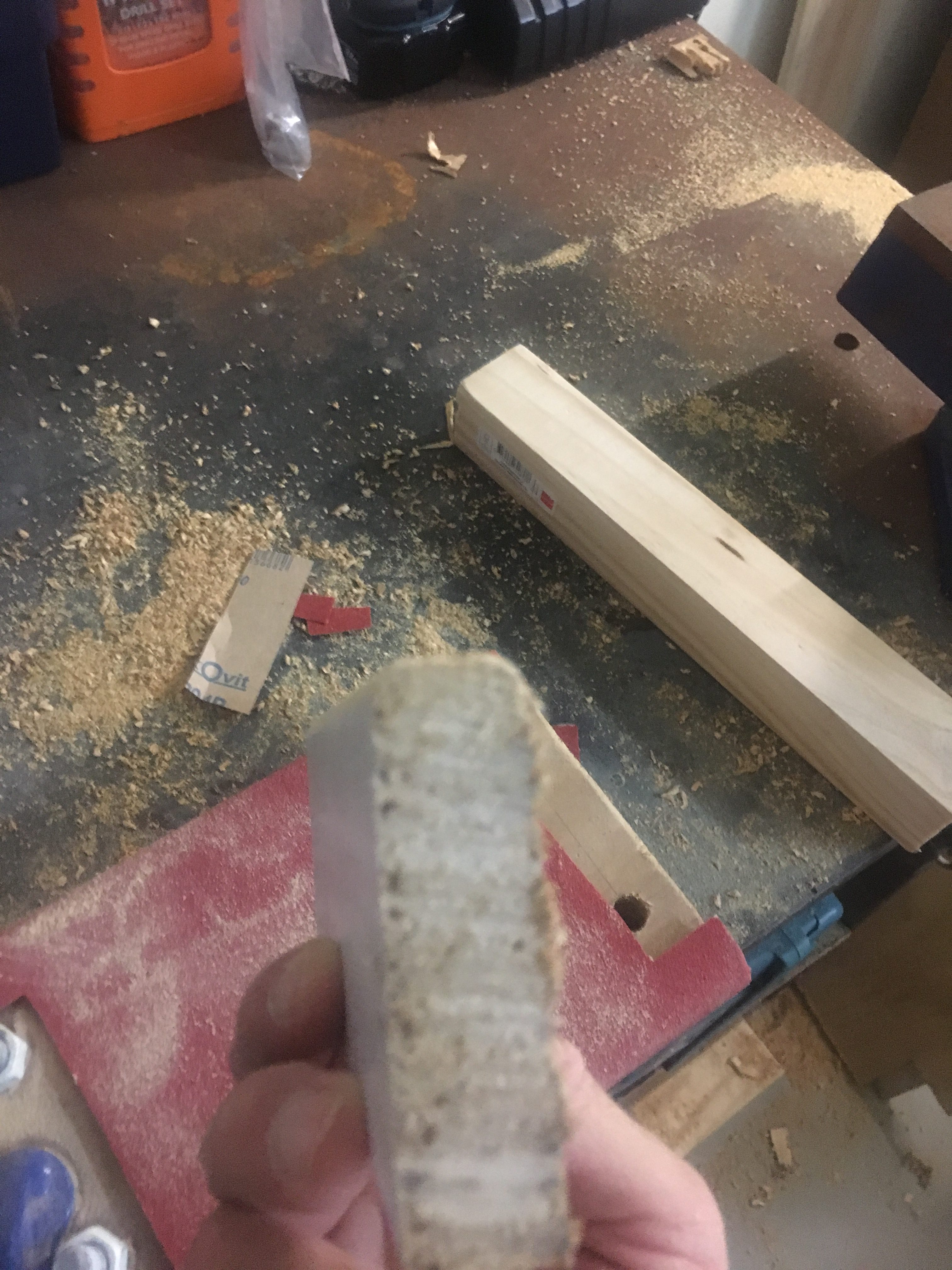
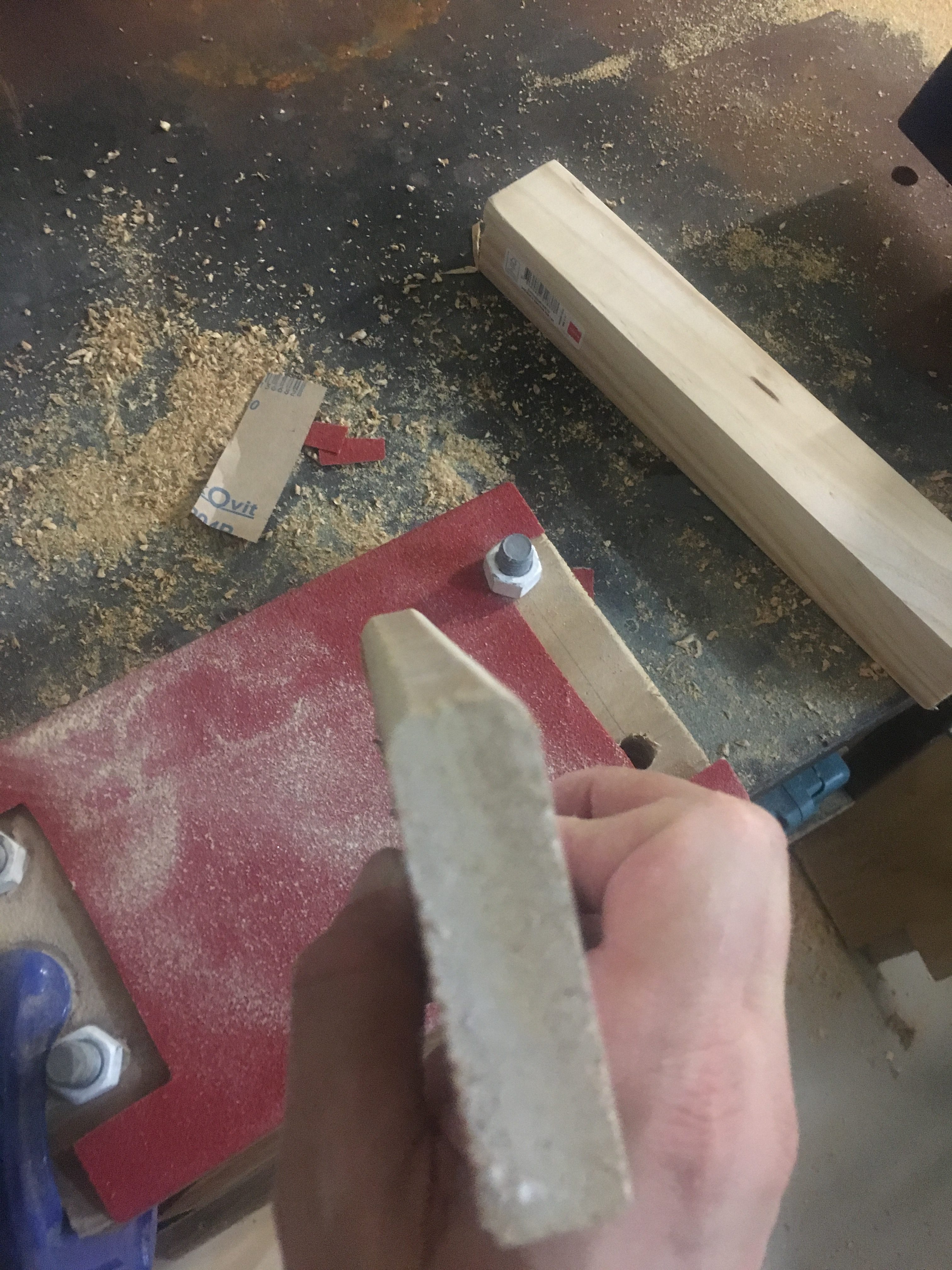
The first tool I created to sand down fins was the following:-


The problem with this is that the sandpaper lifts off from the surface and interferes with the sanding process. The area of sandpaper available sanding is reduced because it needs to be sandwiched between the pieces of wood. Because the longest section of fin to be sanded is 250mm, this means we can’t sand the edge down (along the whole length) in the same stroke. This is a big disadvantage, and was one of the identified issues we wanted to solve.

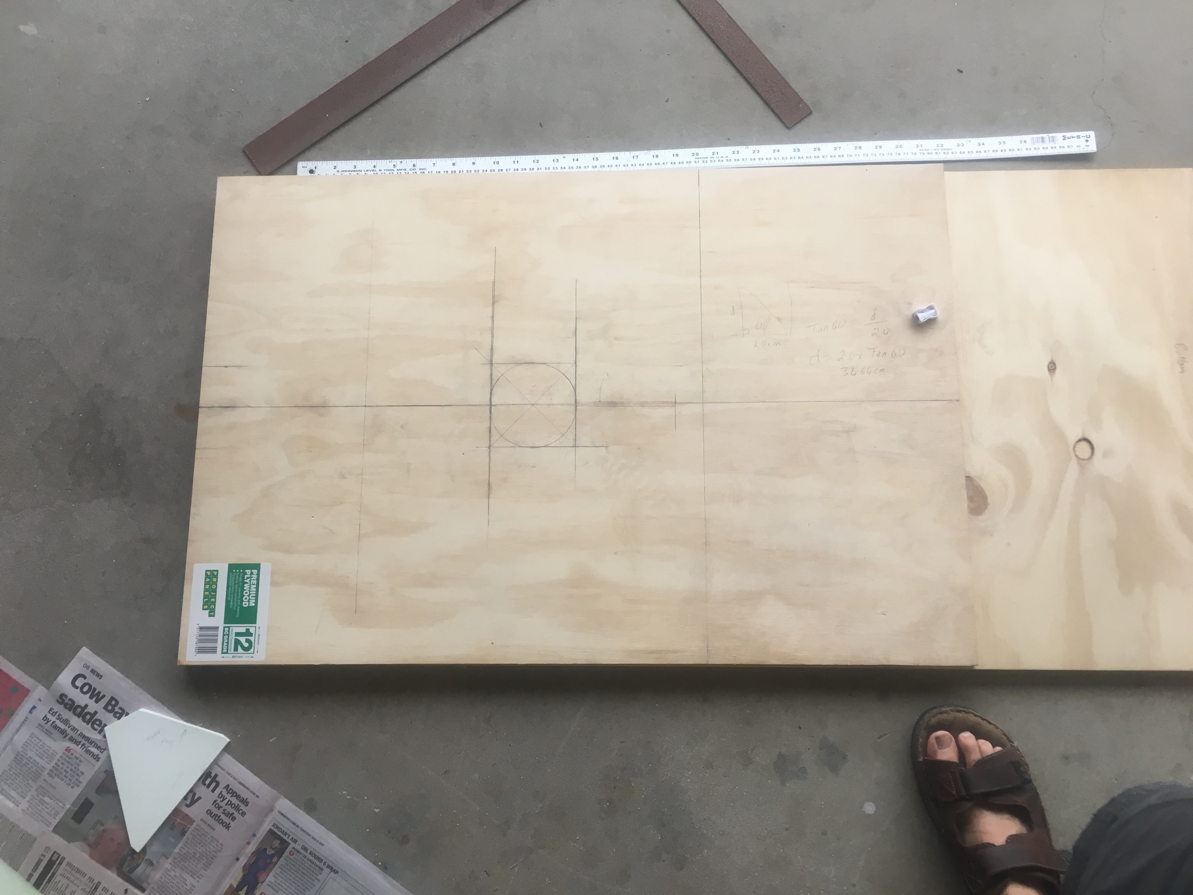
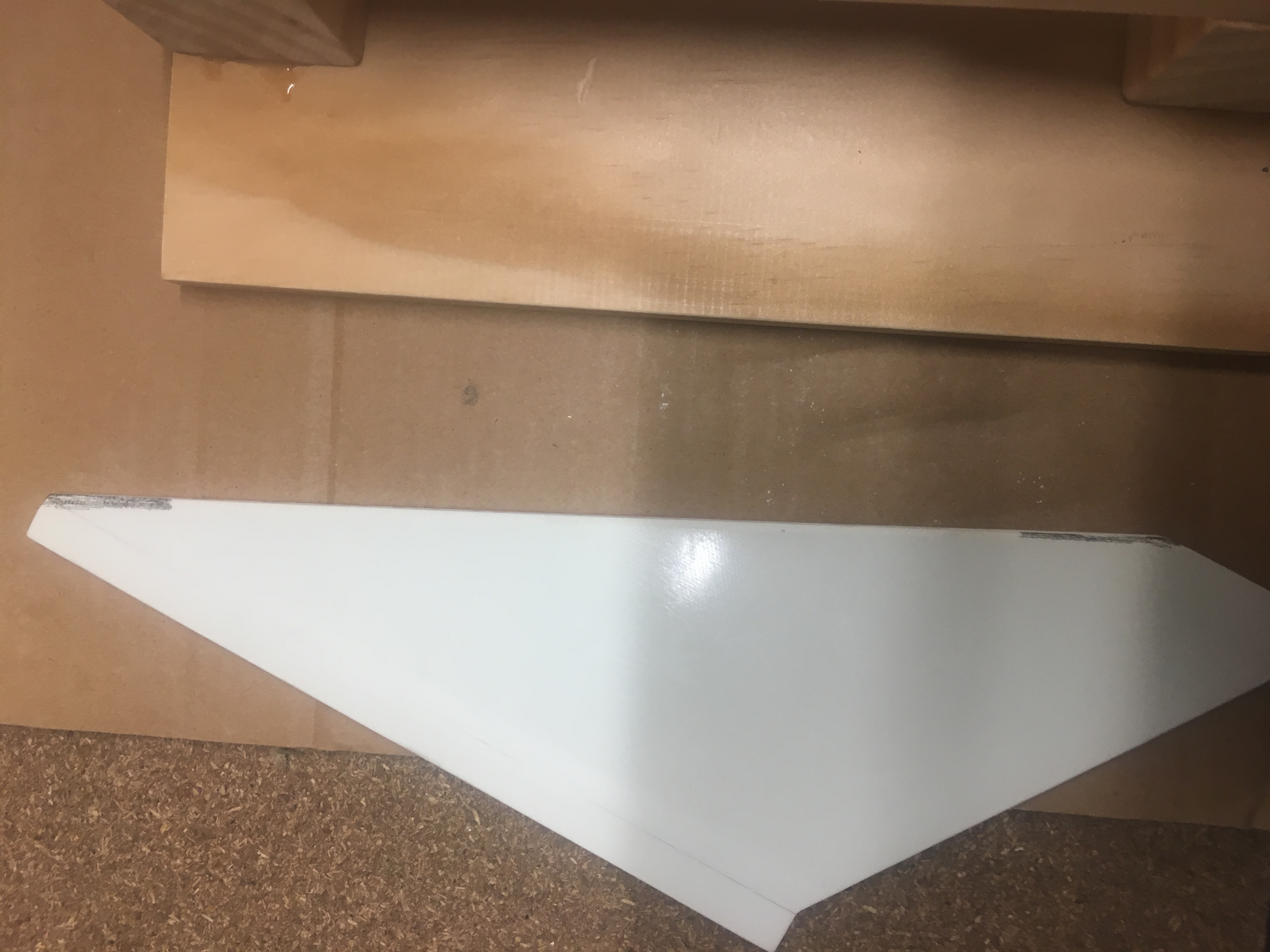
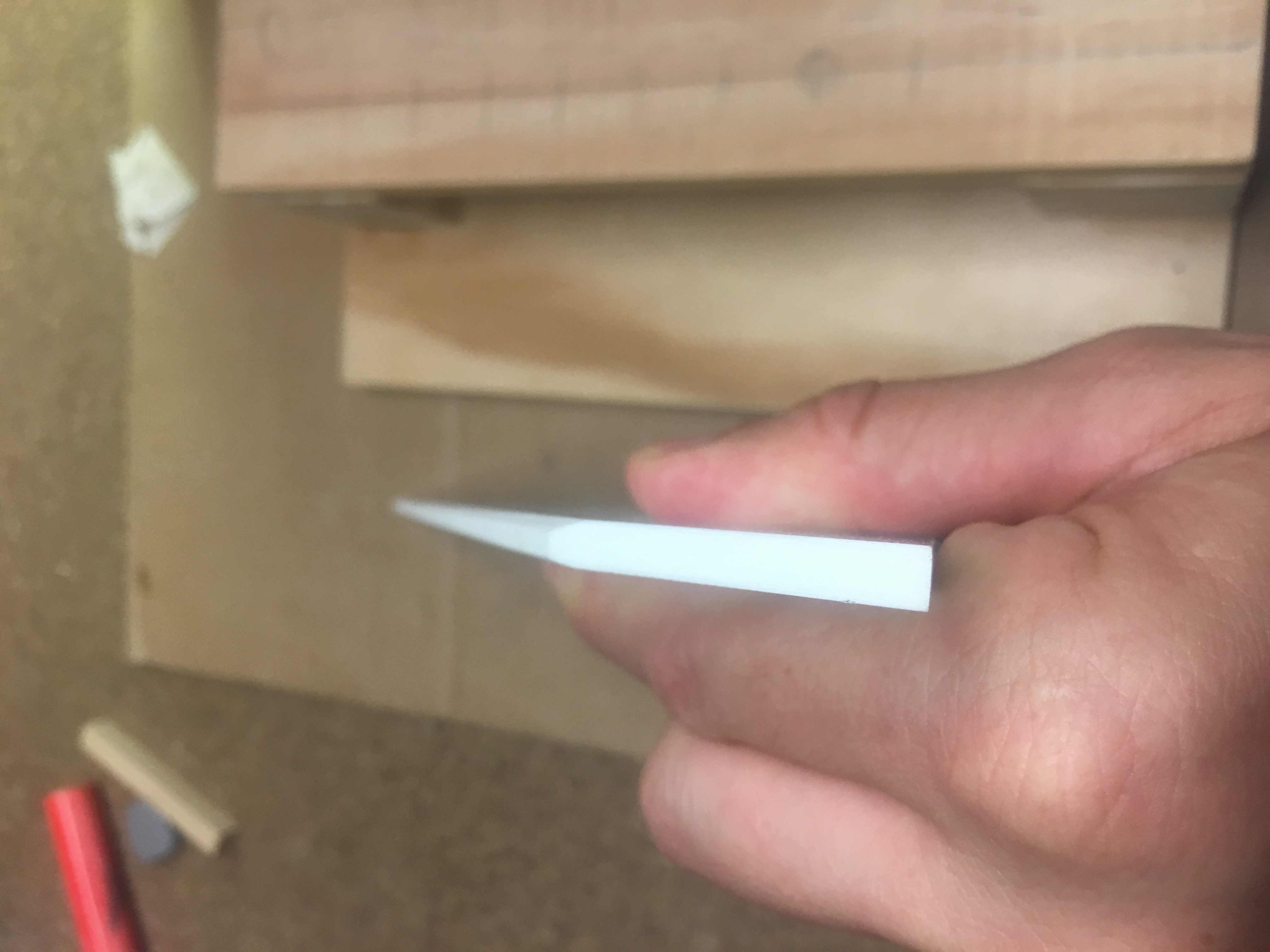
Some tests were done to see if we could get a nice job done using wood and it looks like it “should” work. See below:-

IMG_2925


Good finish on wood - both edges.
Good finish on wood – both edges.

As you can see, the edges look very well curved. I did this curve by doing sanding at ~30 degrees, ~45 degrees, ~60 degrees. Then I did a ‘curving’ action to try and get it rounded. This makes a ‘semi-circle’ like edge.

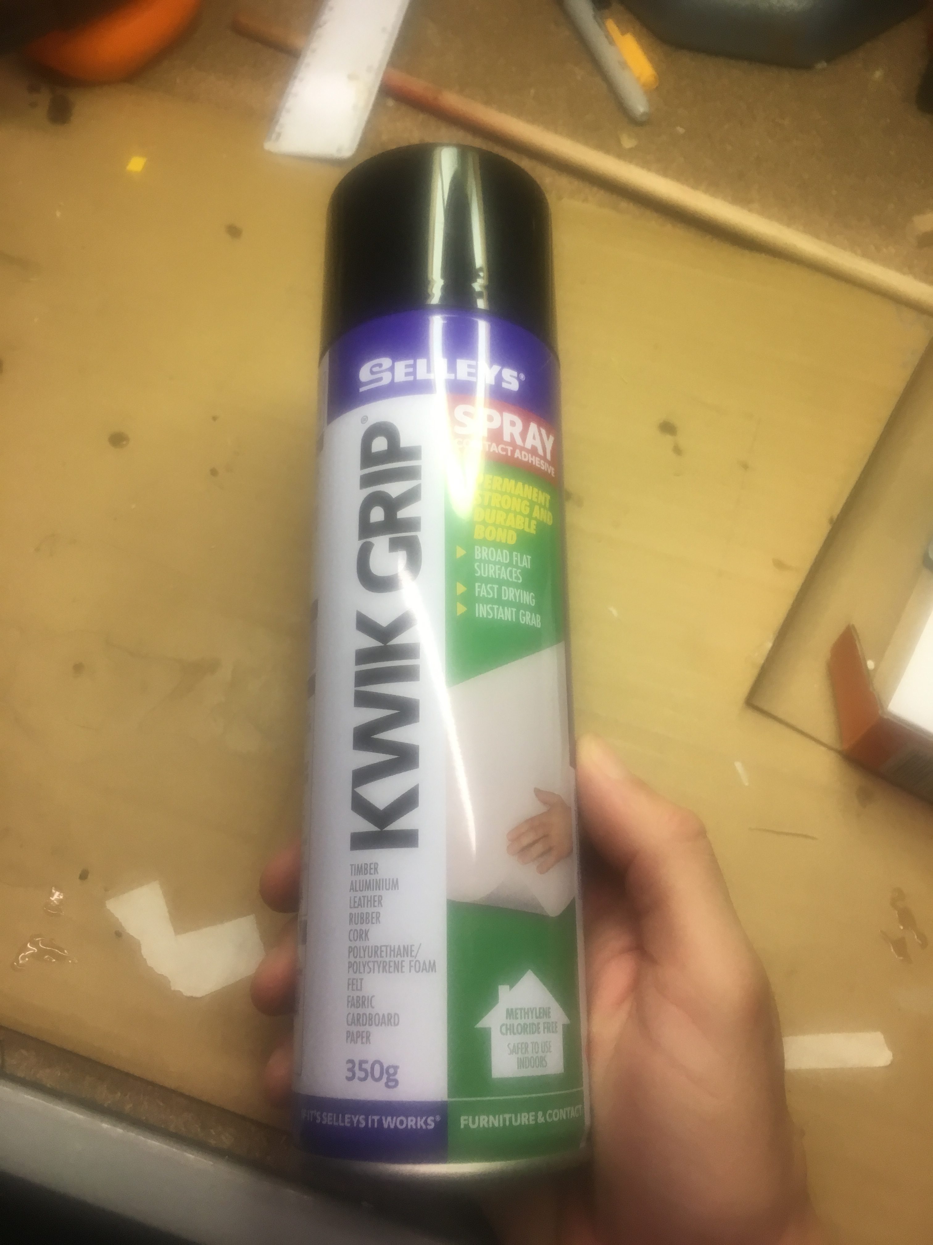
I decided to build a simpler sanding plate. I needed:-

  • Sandpaper
  • Spray Glue
  • Plywood
  • Clamps
Spray Glue
Spray Glue
Sand paper and Plywood

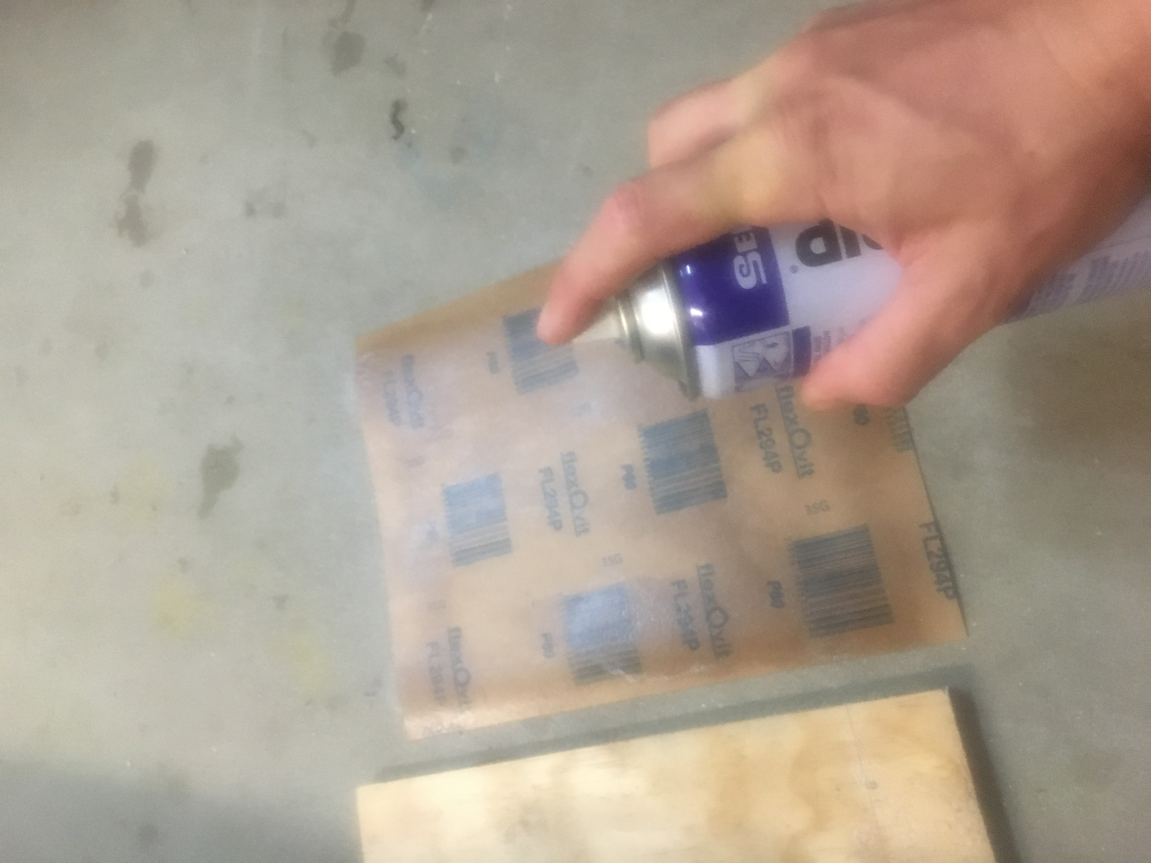
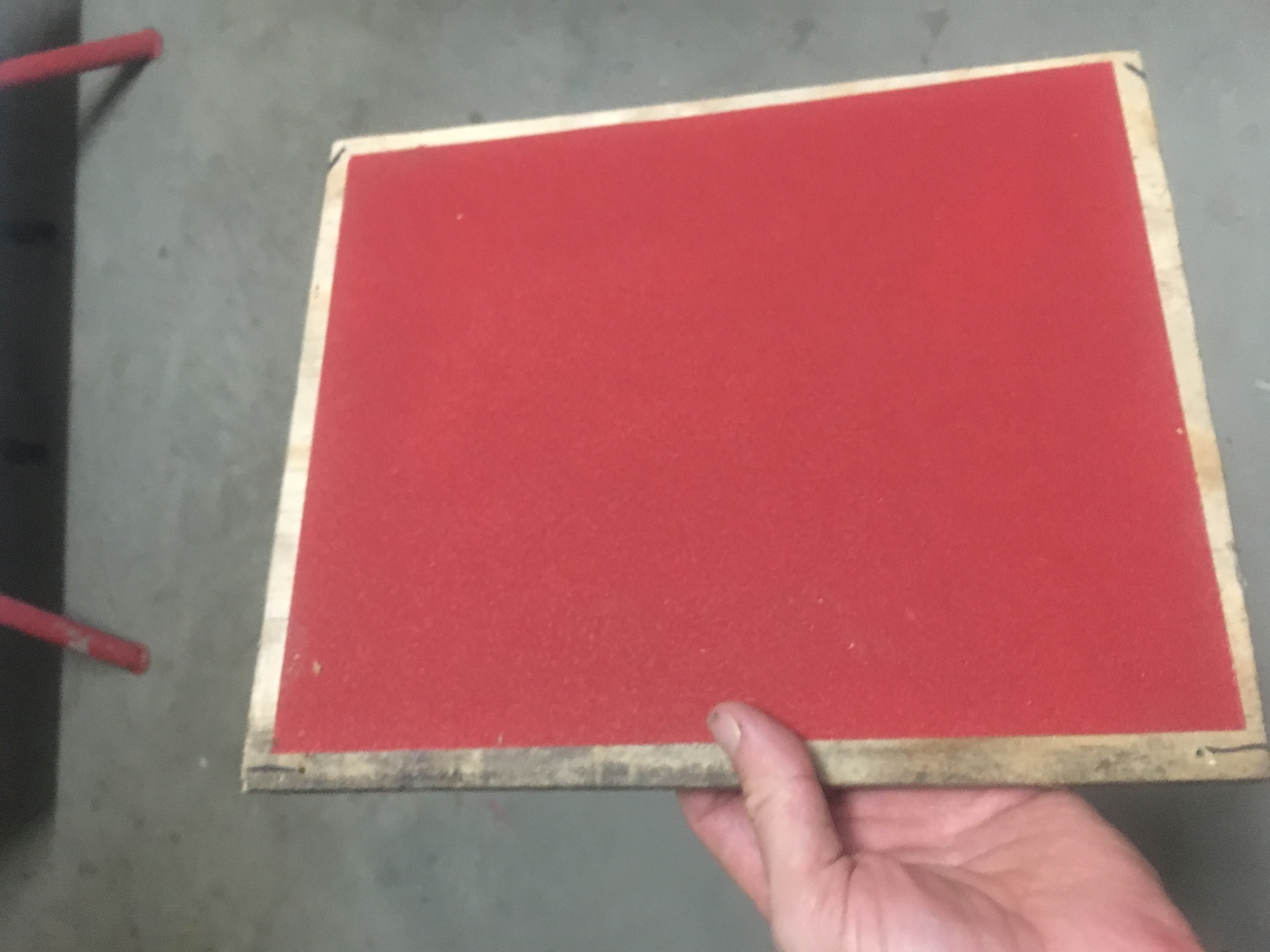
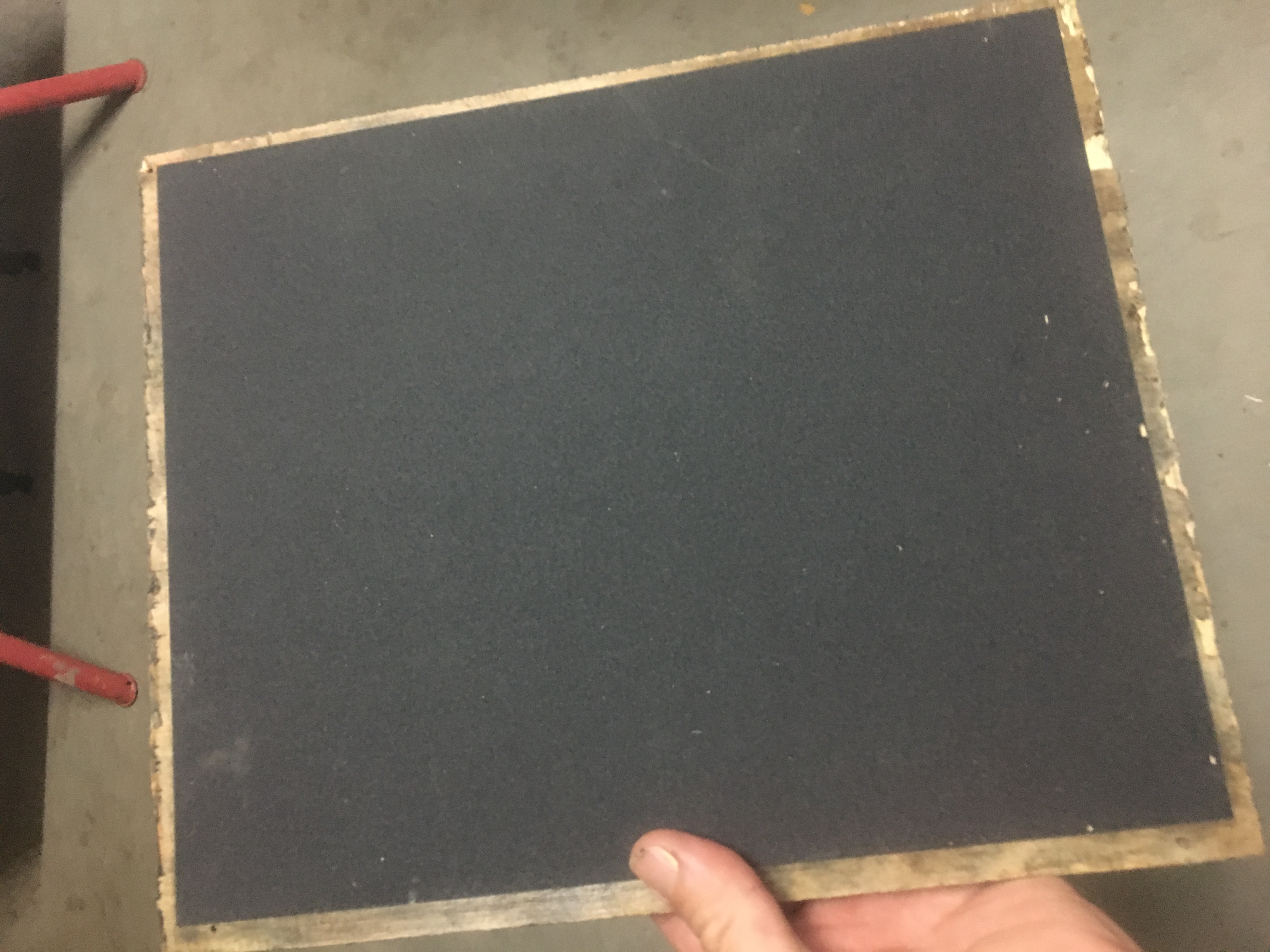
I followed the instructions very carefully. Spraying both the sandpaper and plywood, then letting them sit for 10 minutes. Then I put the two together and I clamped them over night. I decided to put 80-grit sand-paper on one side and 240-grit sand paper on the other side.

Applying Spray glue to sandpaper and to the plywood.
Letting sandpaper and plywood sit for 10 minutes.
Clamping sandpaper and plywood for overnight dry session.

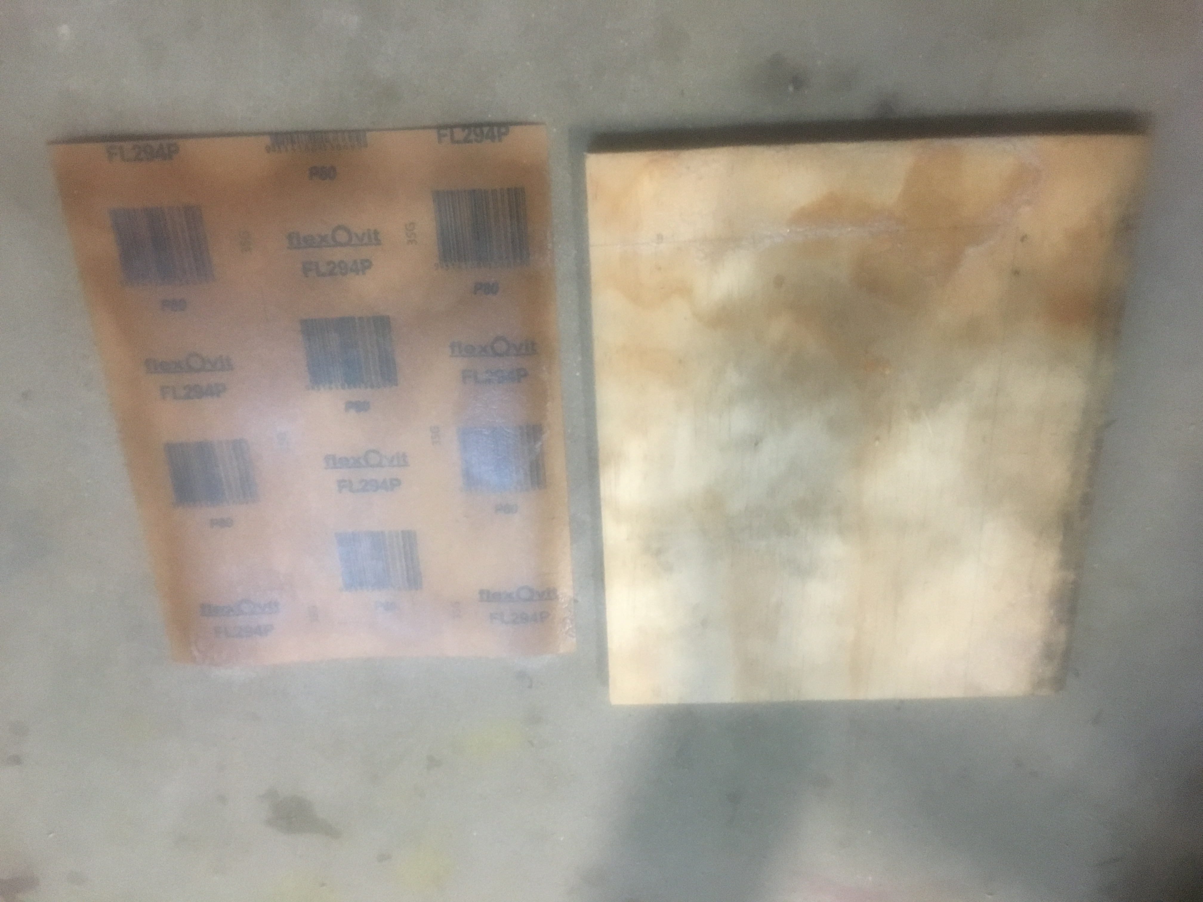
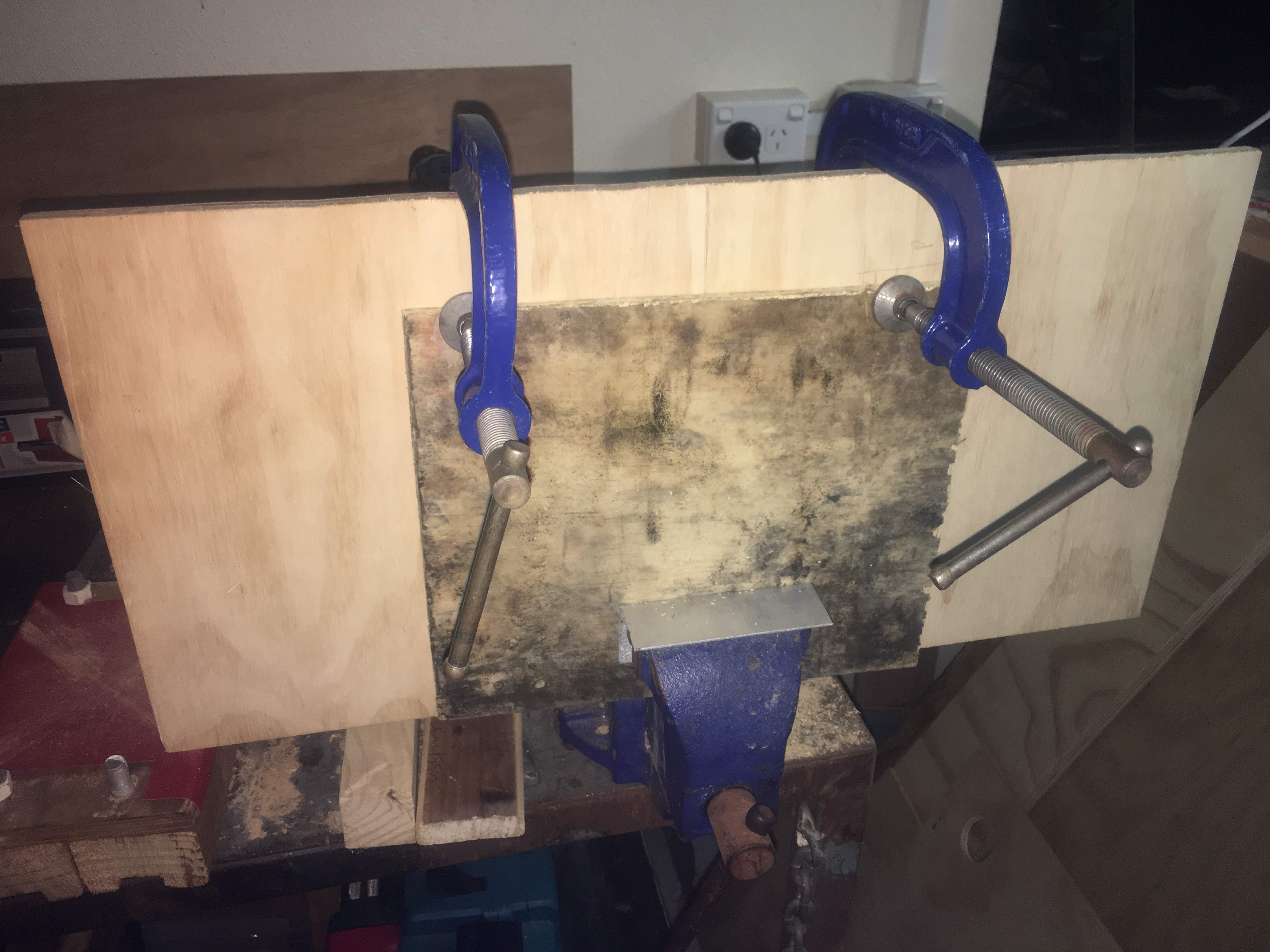
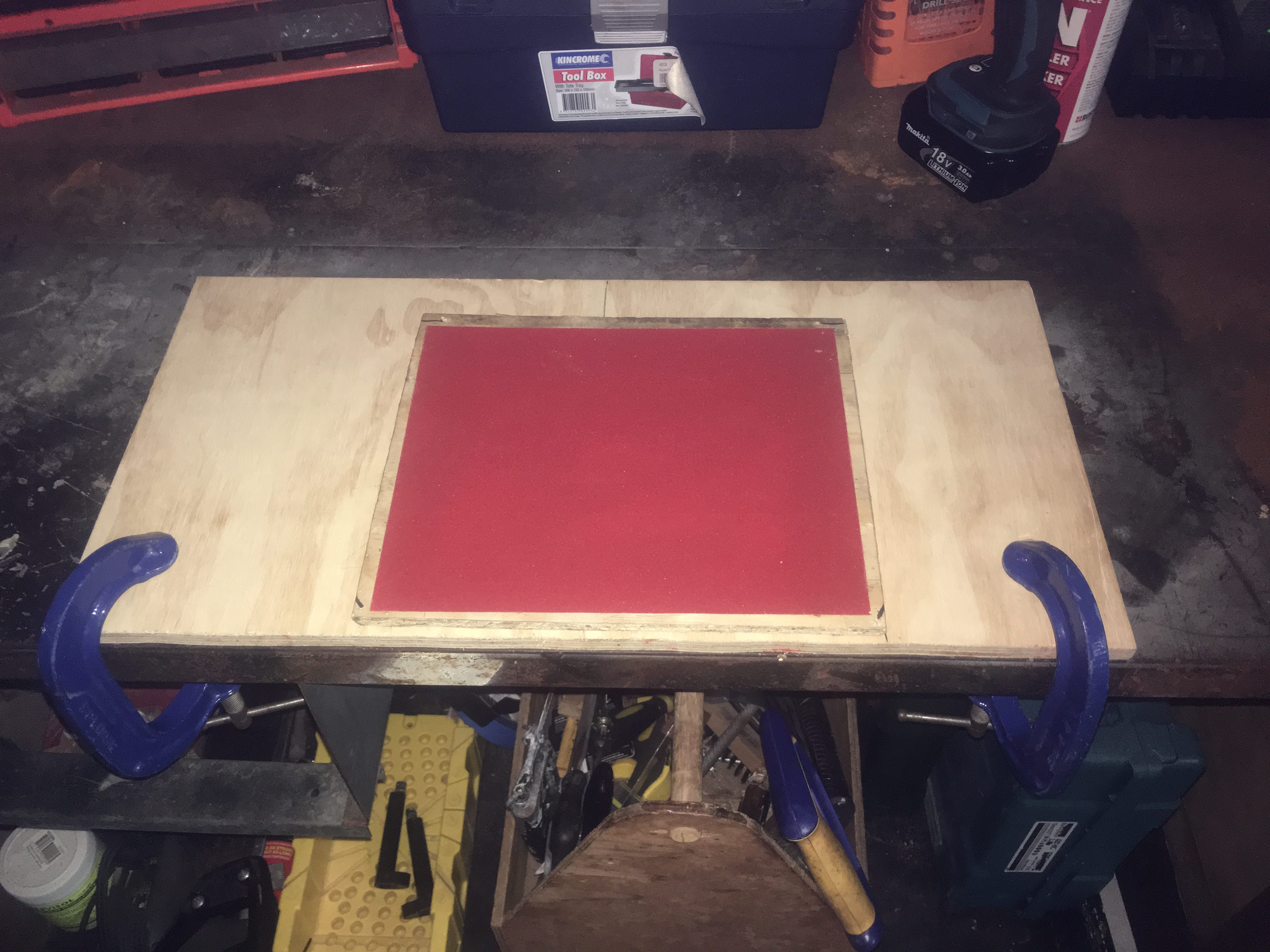
Here is the end result.

80-grit Sandpaper on one side.
240-grit Sandpaper on one side.

Notice how there is some bare plywood accessible on the edge of the sanding board. We have drilled some holes into this can can mount this to a large piece of plywood. This allows mounting the sanding board on a solid (non-moving) bench. See below.

Fix sanding board to big piece of plywood which in turn is clamped to desk


Assembly Jig for Attaching the Fins

One of the steps I’m coming up to is the attachment of the fins to the Air-frame/Motor Mount. For a good join and a good rocket build it is important that we:-

  • Sand/score the root of the fins
  • Sand the Motor Mount where they are going to be glued
  • Sand/score the Tang of the Fins for the fillets later on
  • Important that the Fin/rocket do not move for 3 days while it dries
  • Very important that the fins are precisely 120 degrees apart and are perpendicular to the air-frame

The the last two bullet points, we have build up a “jig” to hold everything in place. Below are some pictures of it.

Marking where to cut out circle


Two pieces of wood assembled so we can cut out circle sections together.
Cut out circle and marking where cut-outs are going to be for protruding fins.


Fin Assembly from back. Notice the right-angle bracket to keep it vertical.
Fin Assembly from front


Side view showing how fins are kept in line with two pieces of wood and three bolts.


We want to hold the fins completely still while it is drying. For this, we have used two square pieces of timber and some G-clamps to keep the fins steady. See the photo below.

Fins held in position using wood braces/G-clamps.