38mm CTI and AeroPak motors come buy default with approx 1.4 grams of Black Powder for their ejection charges. Based on this and the fact my rocket has half of volume blocked off by engine block, I decided to start my ejection charge tests at 0.75 grams. Ultimately I got up to 1.76 grams of BP. This post discusses this in detail.
How the system is packed.
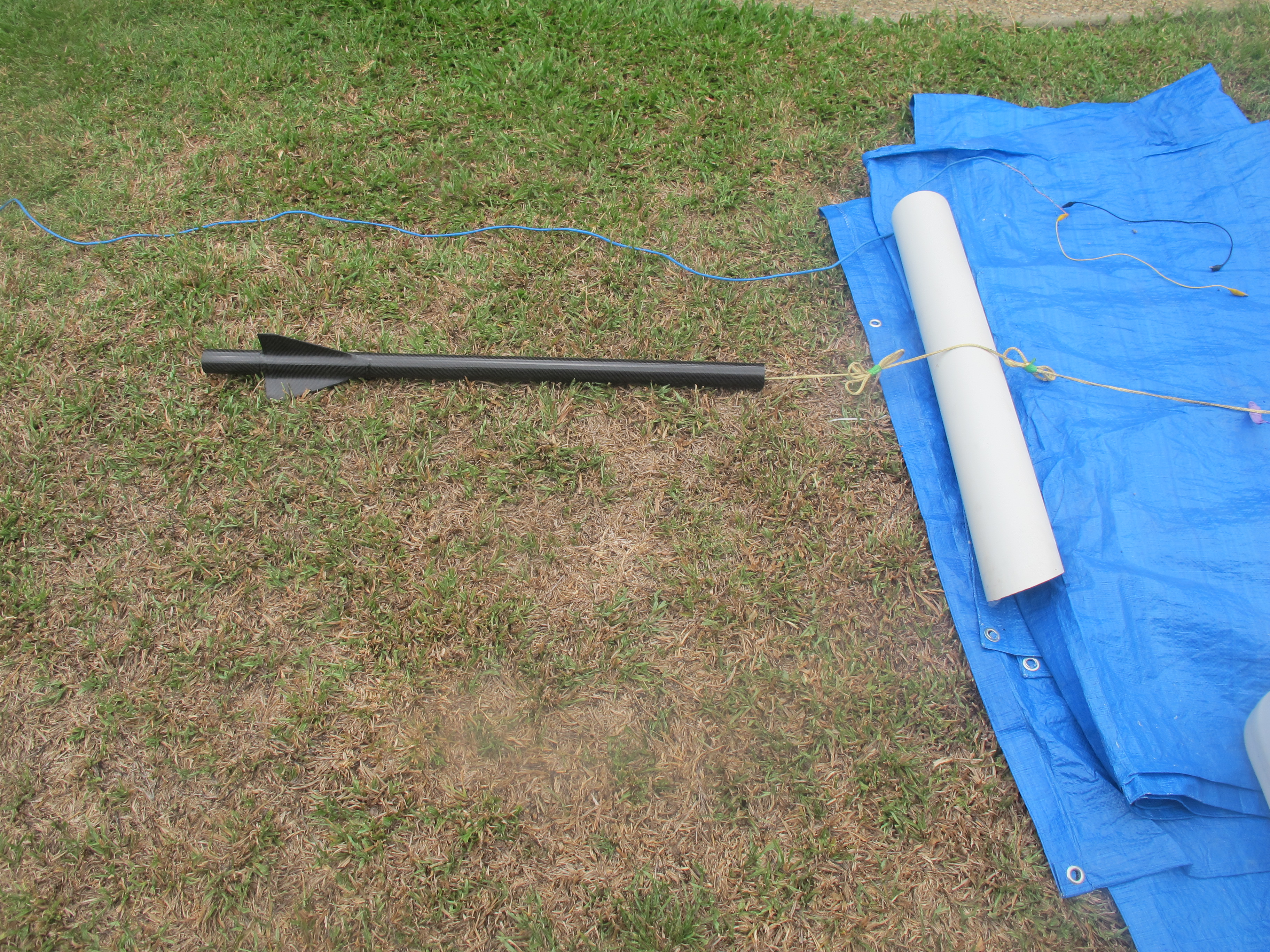
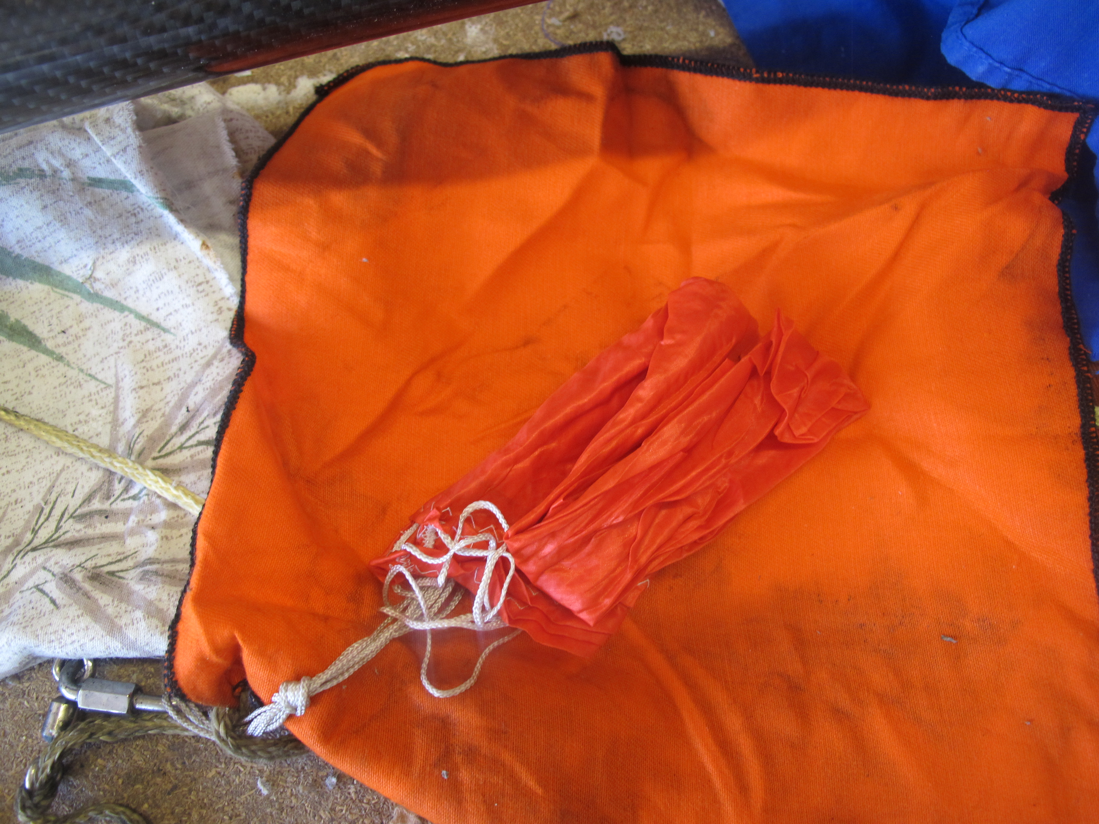
This is probably the best place to describe how the recovery system was packed, because the tests identified a possible issue with the set-up.
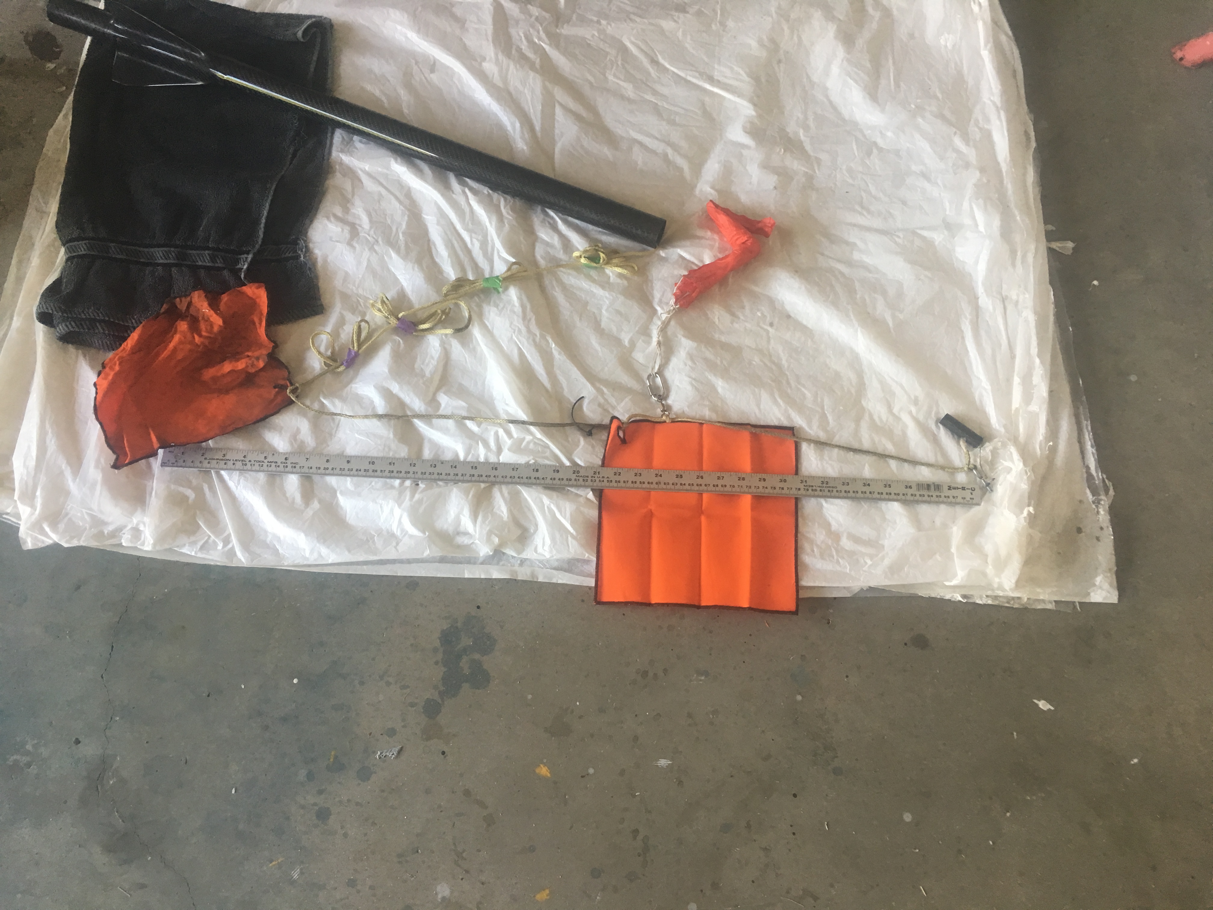
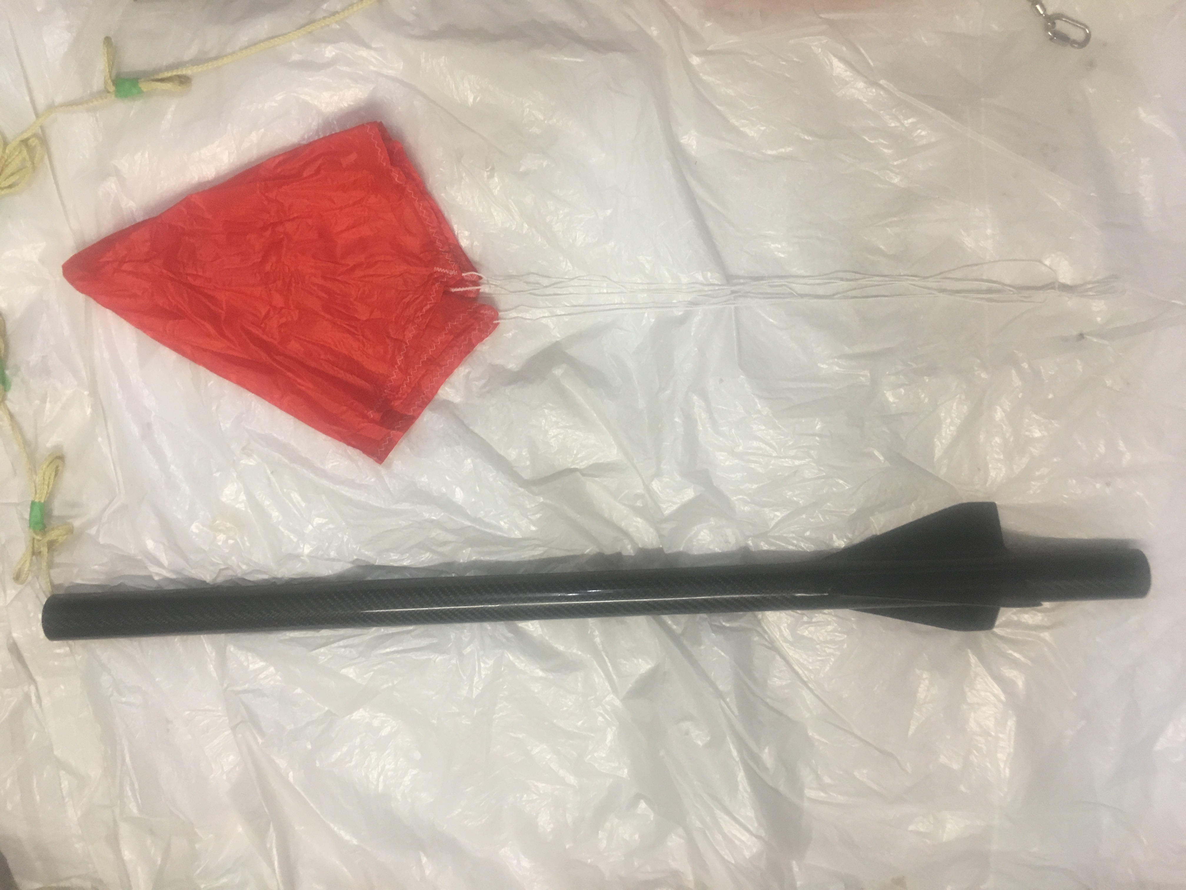
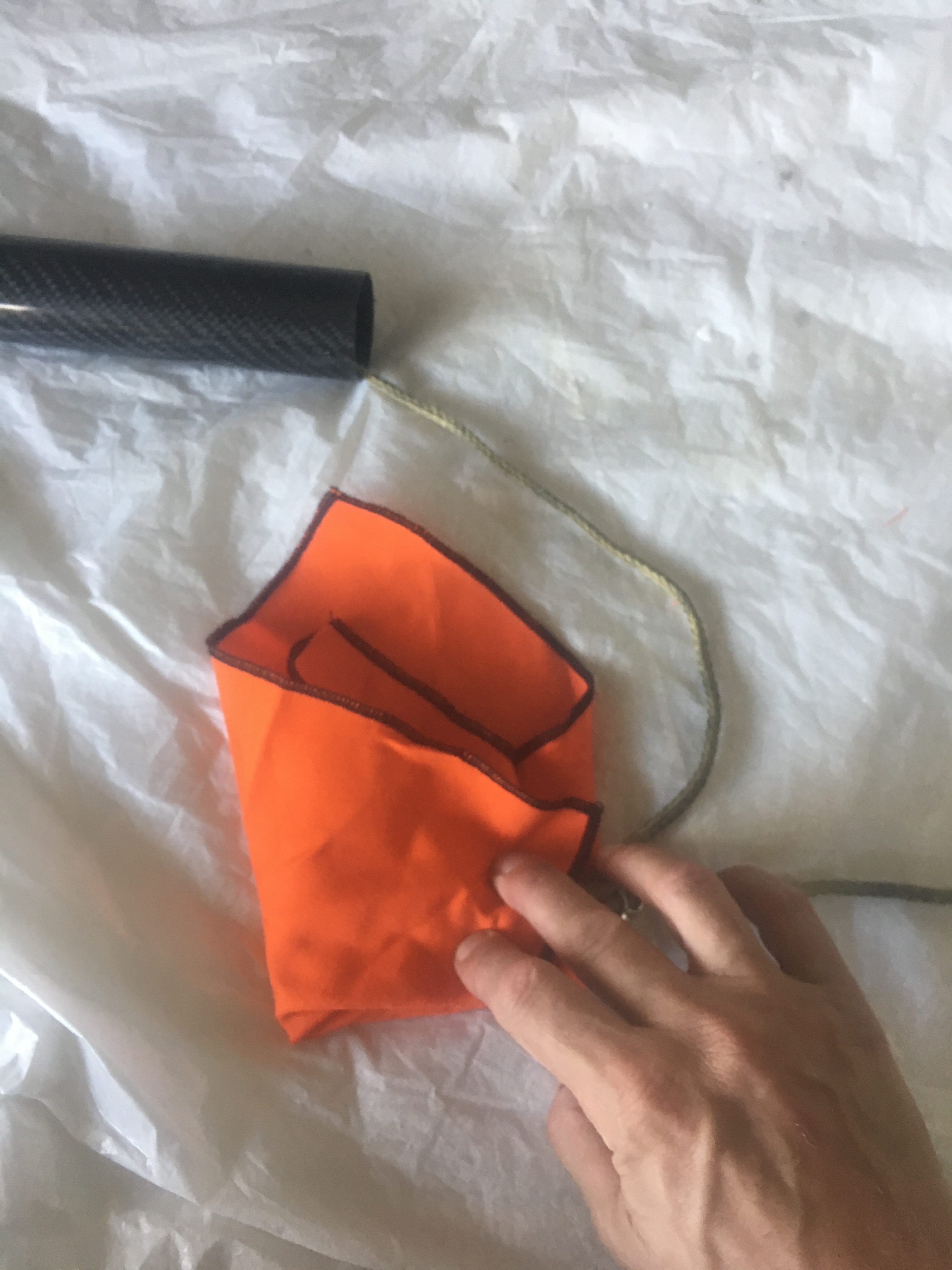
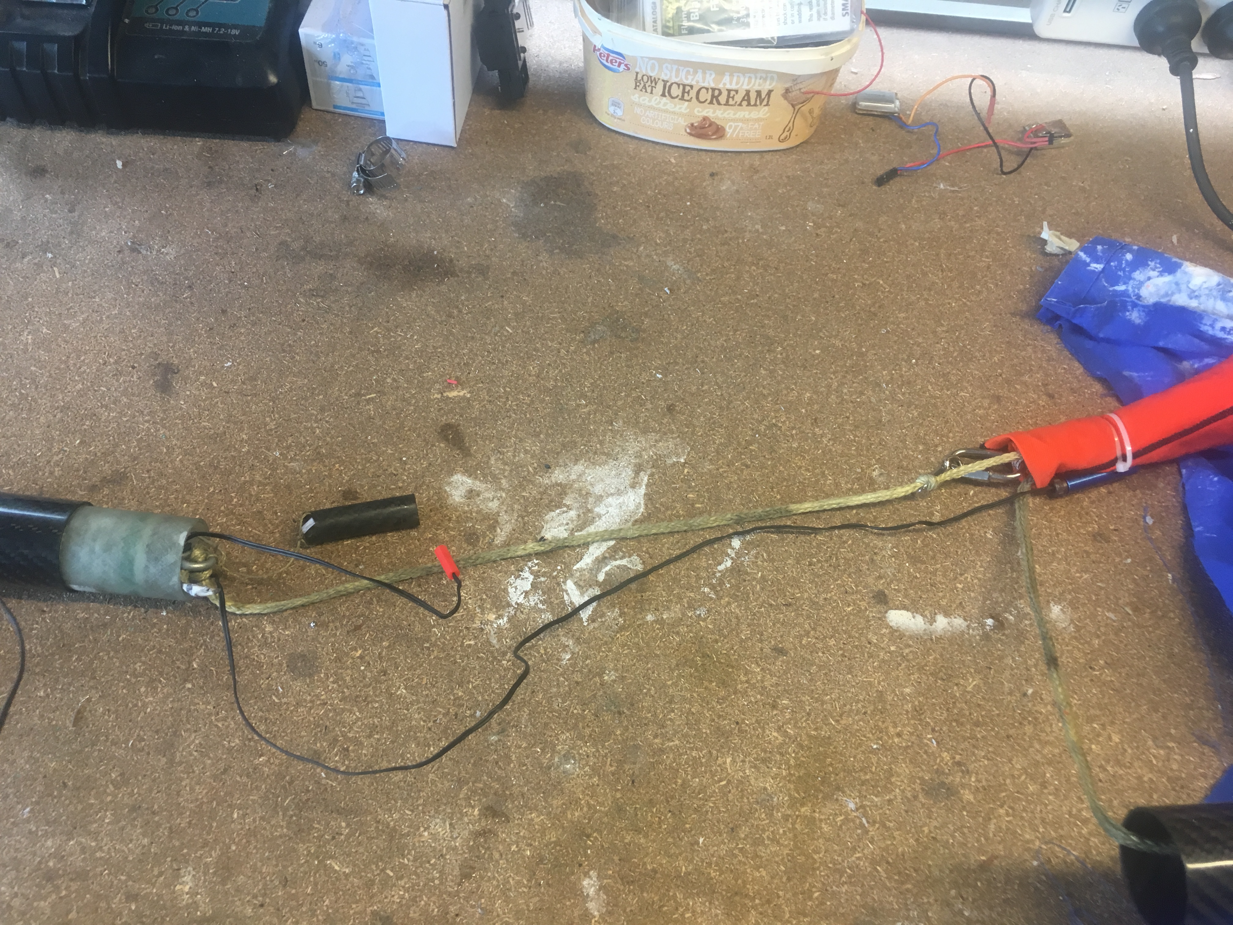
View of all the components to be packed into air-frame – prior to folding and attaching igniters, cable cutter.
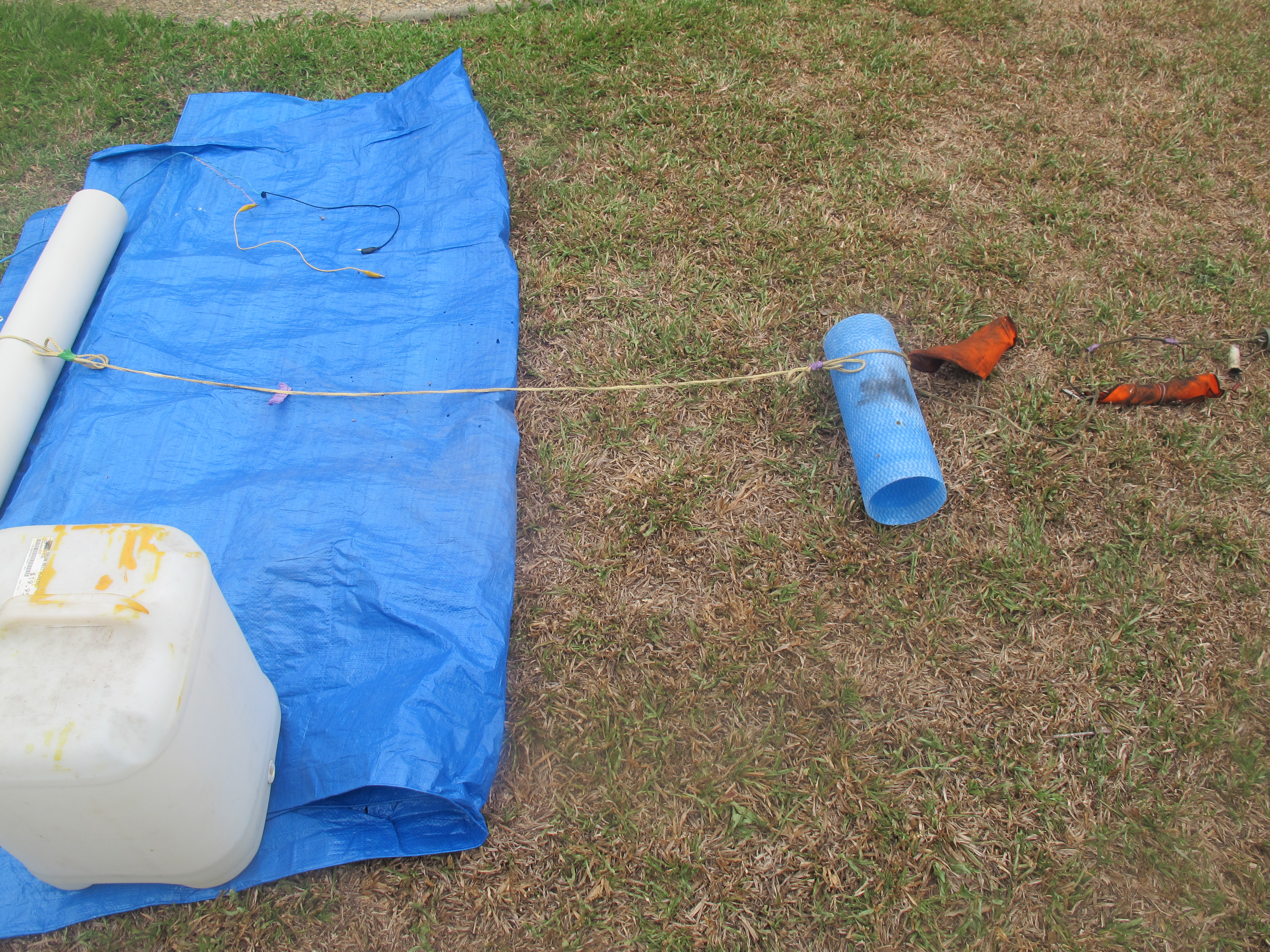
You will notice in this photo there are TWO Nomex blankets. The left one covers the shock-cord (but its primary purpose is add additional drag) and the other Nomex blank protects the parachute. The right Nomex blanket is held in place with a Cable Cutter, the right is simply wrapped into a bundle.
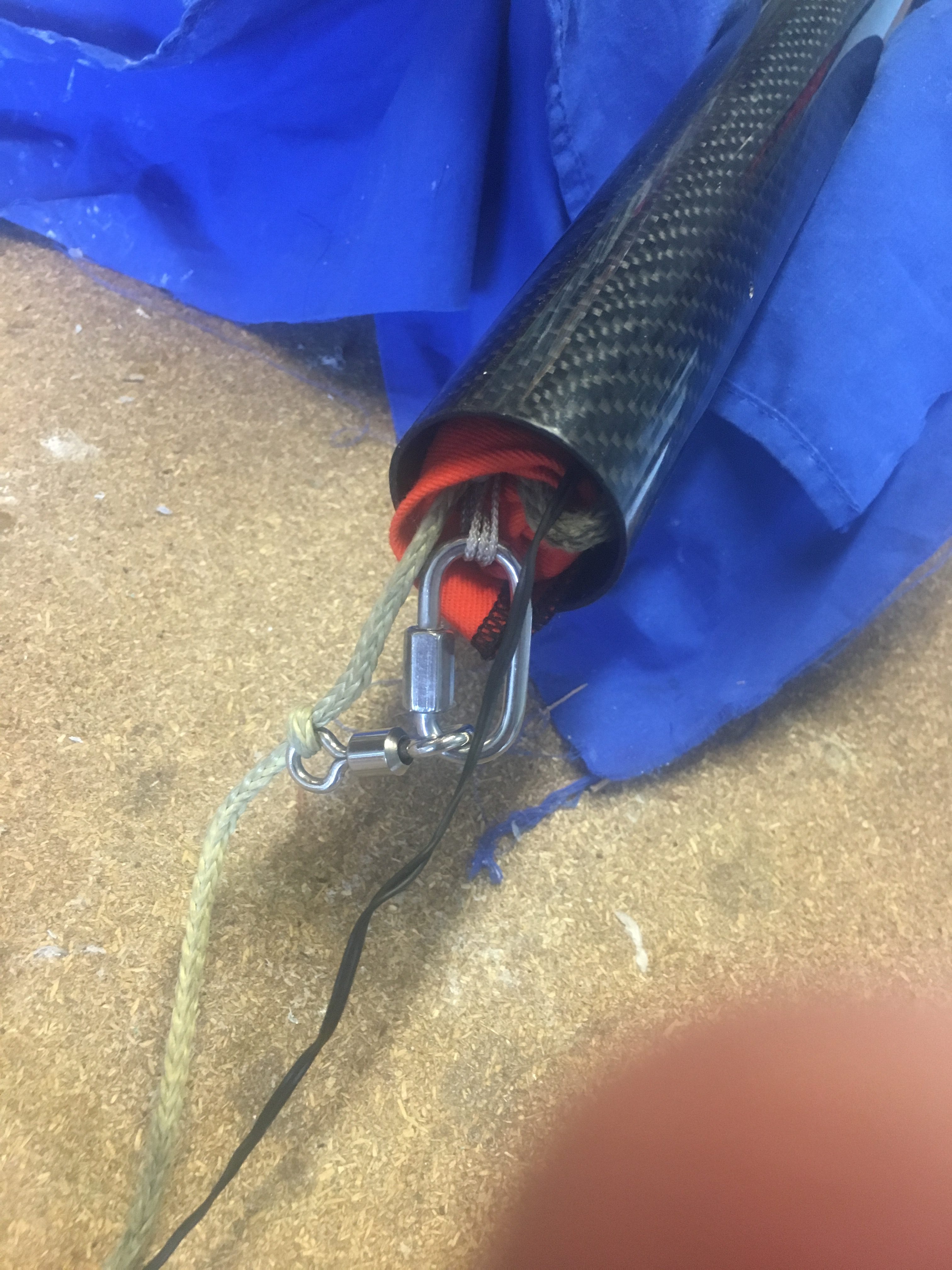
The parachute is on a Swivel and uses a 4mm Quick-Link. The Shock-cord is 5 metres in length, with 0.5 meters inside the air-frame. Notice the use of Z-Folds.
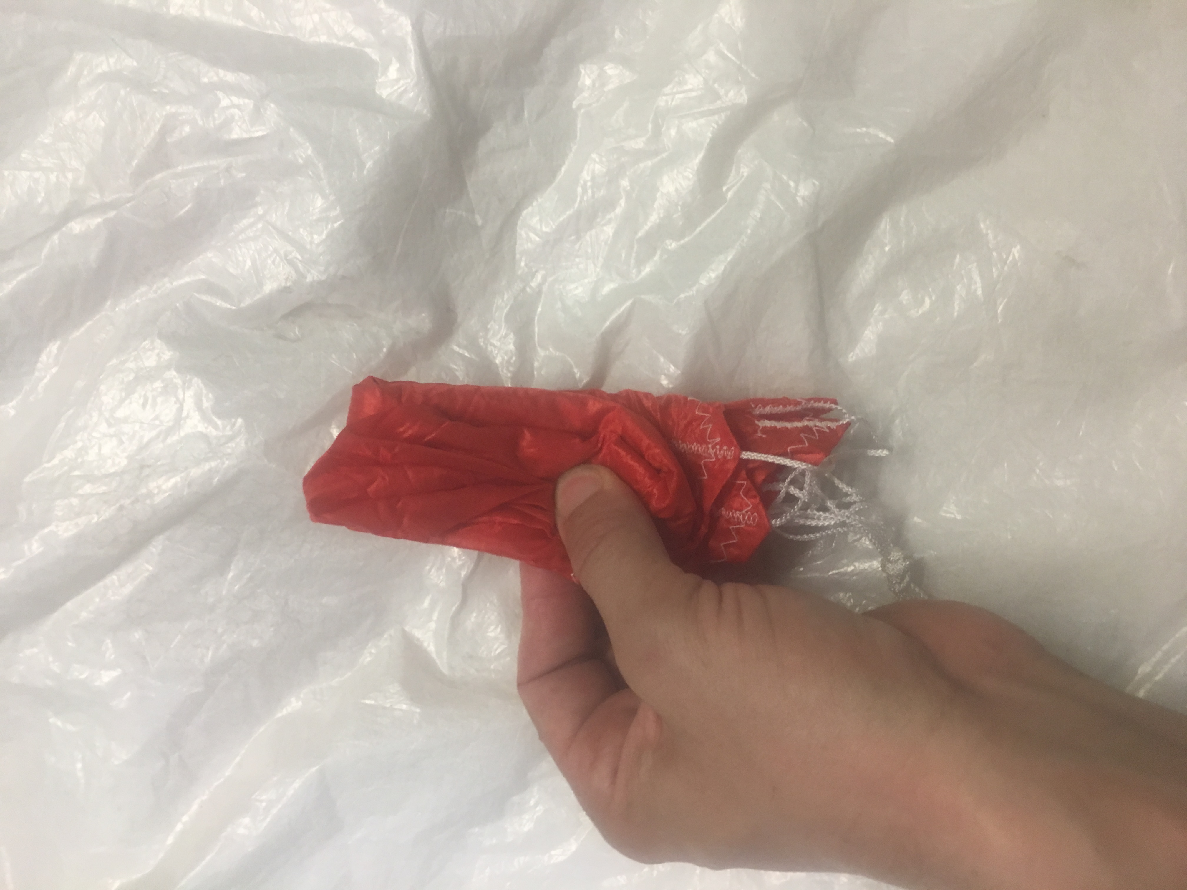
How the Parachute is folded
Here are some photos of how it was folded.
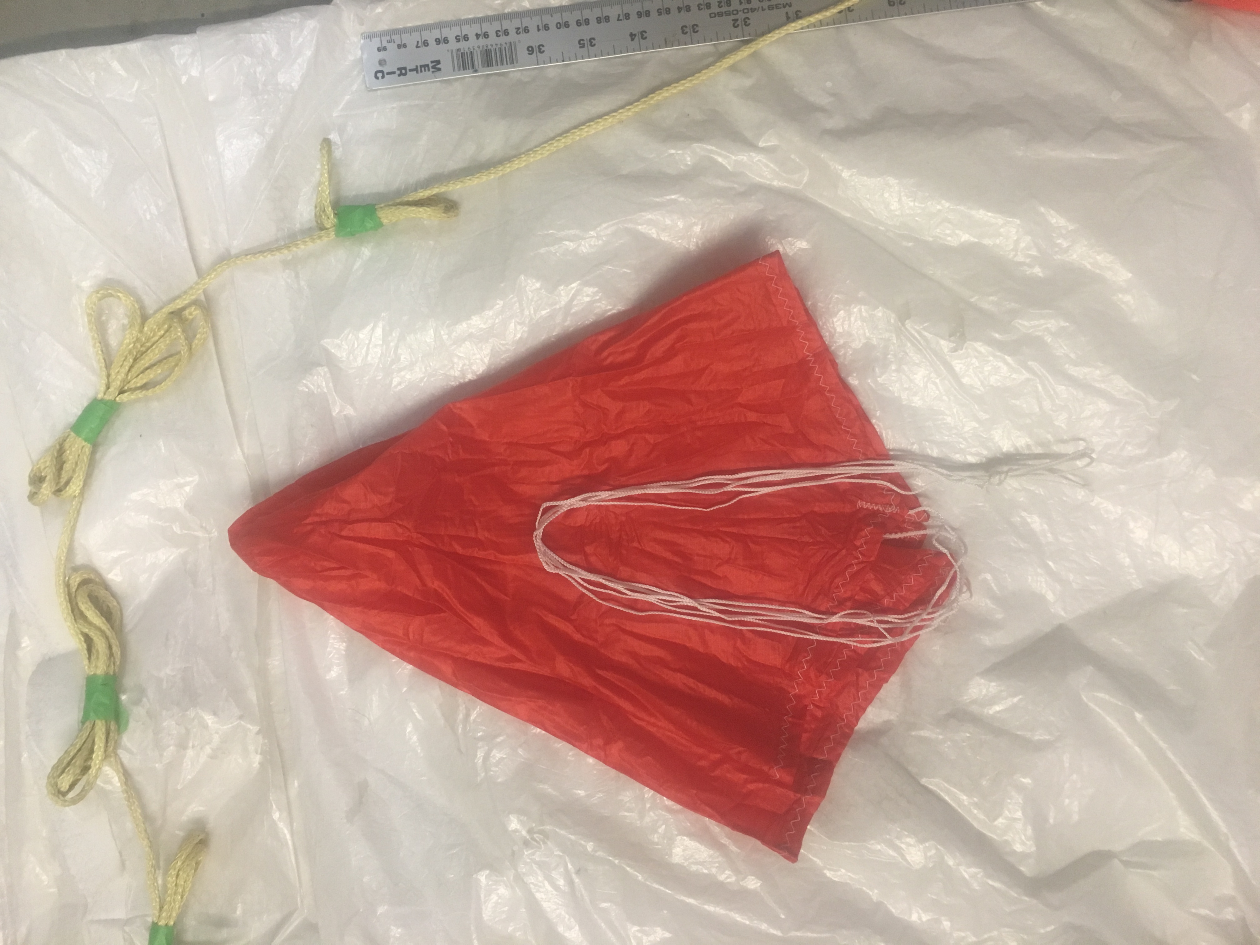
Making sure parachute has no damage and shroud lines are not tangled.Laying out the parachute, shroud lines taut.
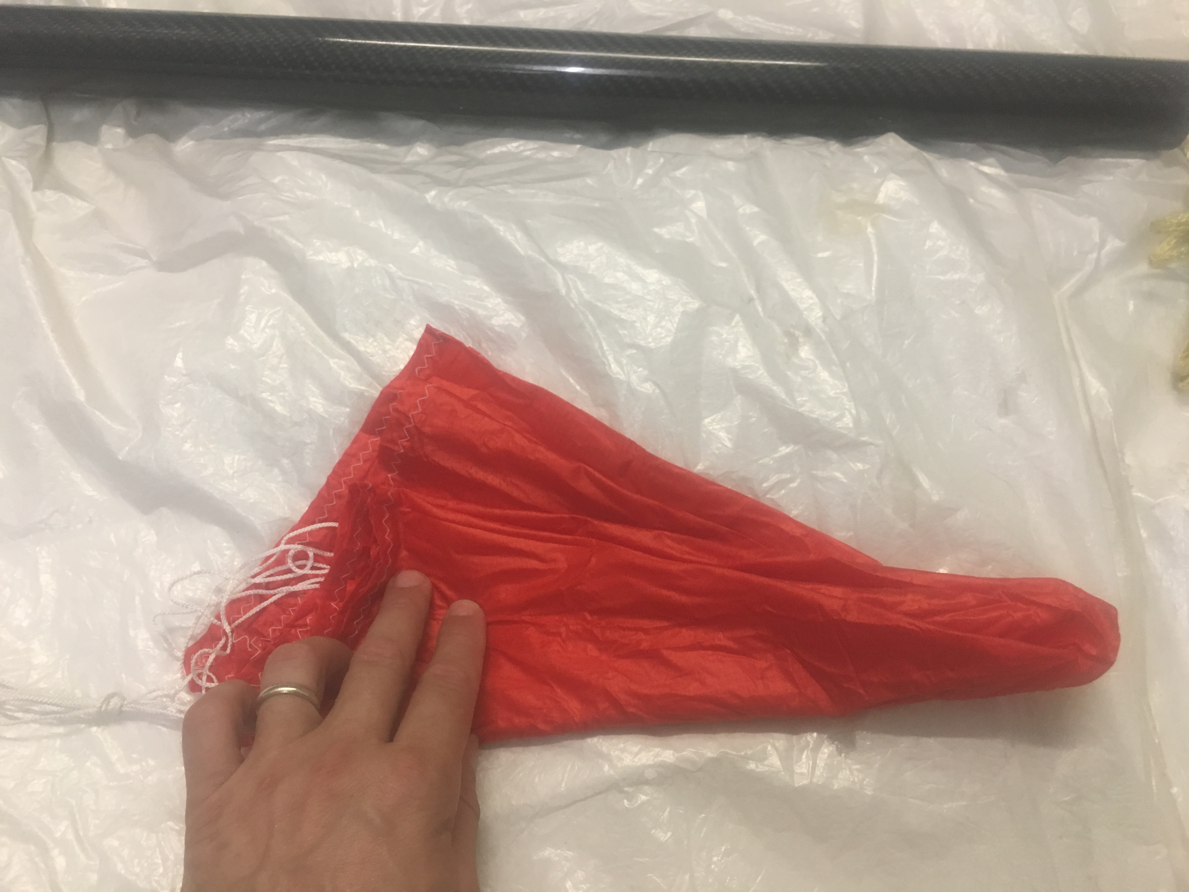
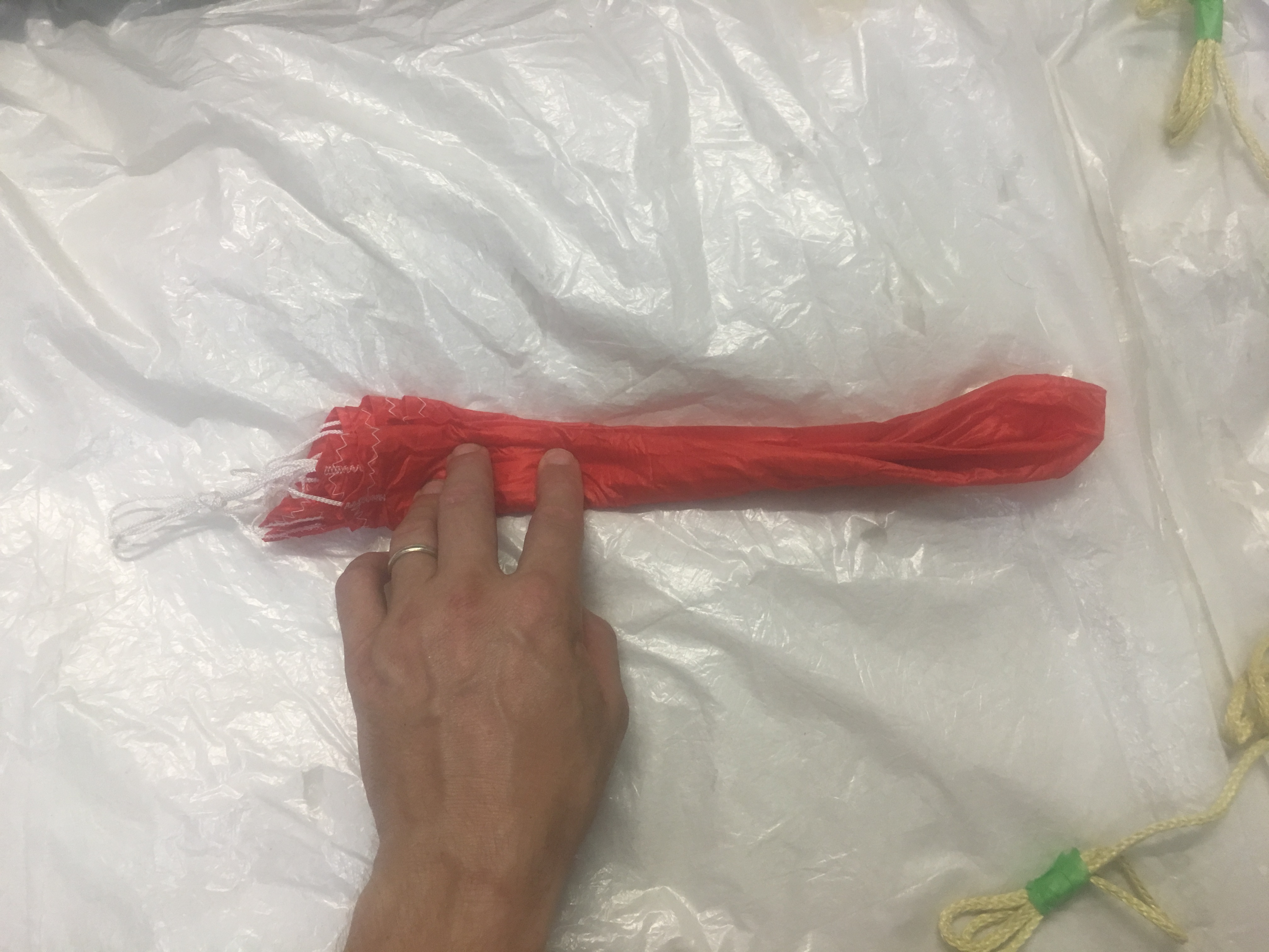
Making sure all the parachute gores are equally aligned and neat.Ensuring all gores are split evenly on each side of the shroud lines.Putting most of shroud lines about 3/4 up the parachute skirt.Folding bottom “third” up….and then top third down.Folding over again.z-folding into three.
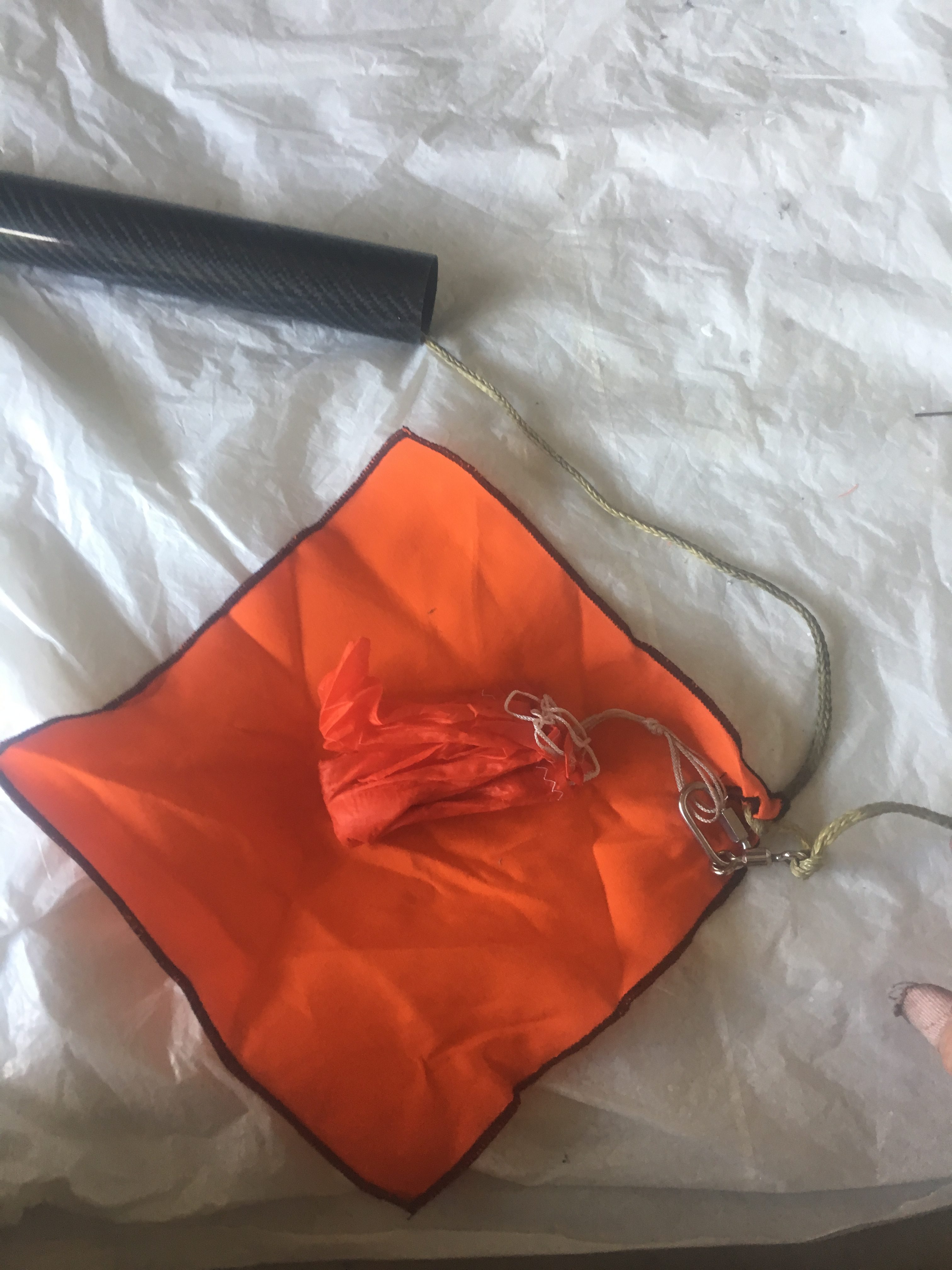
Protecting Parachute with Nomex Blanket
Place bundle in the centre of the Nomex blanket, with the shroud lines pointing to the right. Make sure the quick link is just outside the bundle.
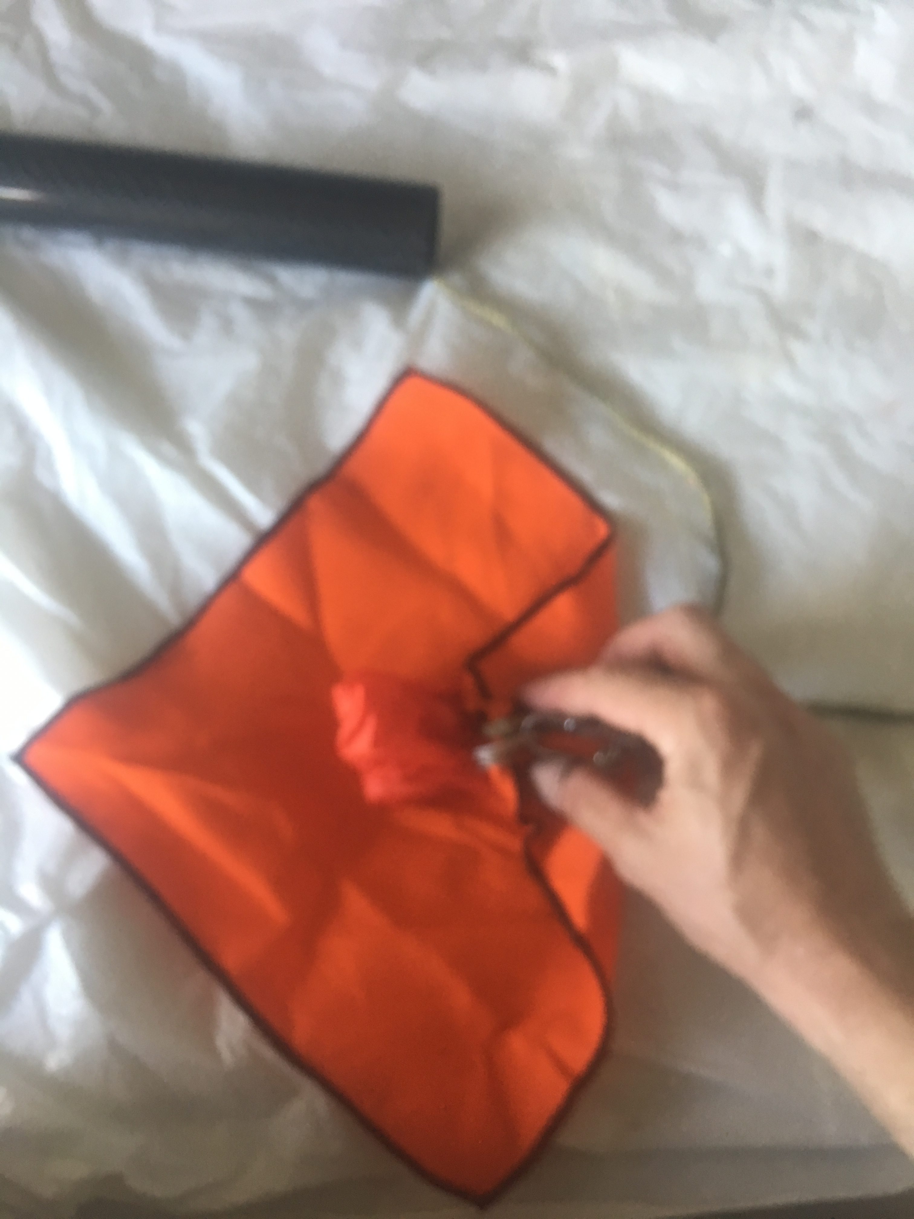
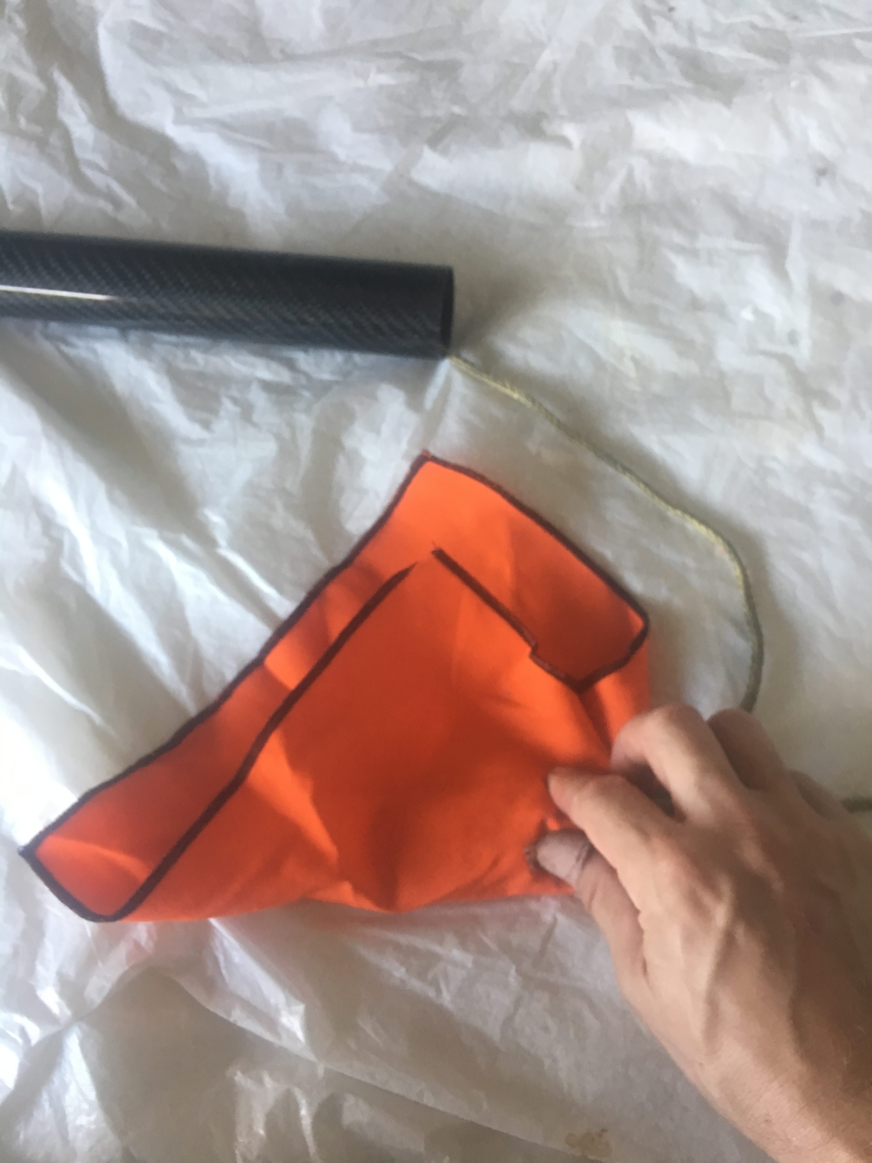
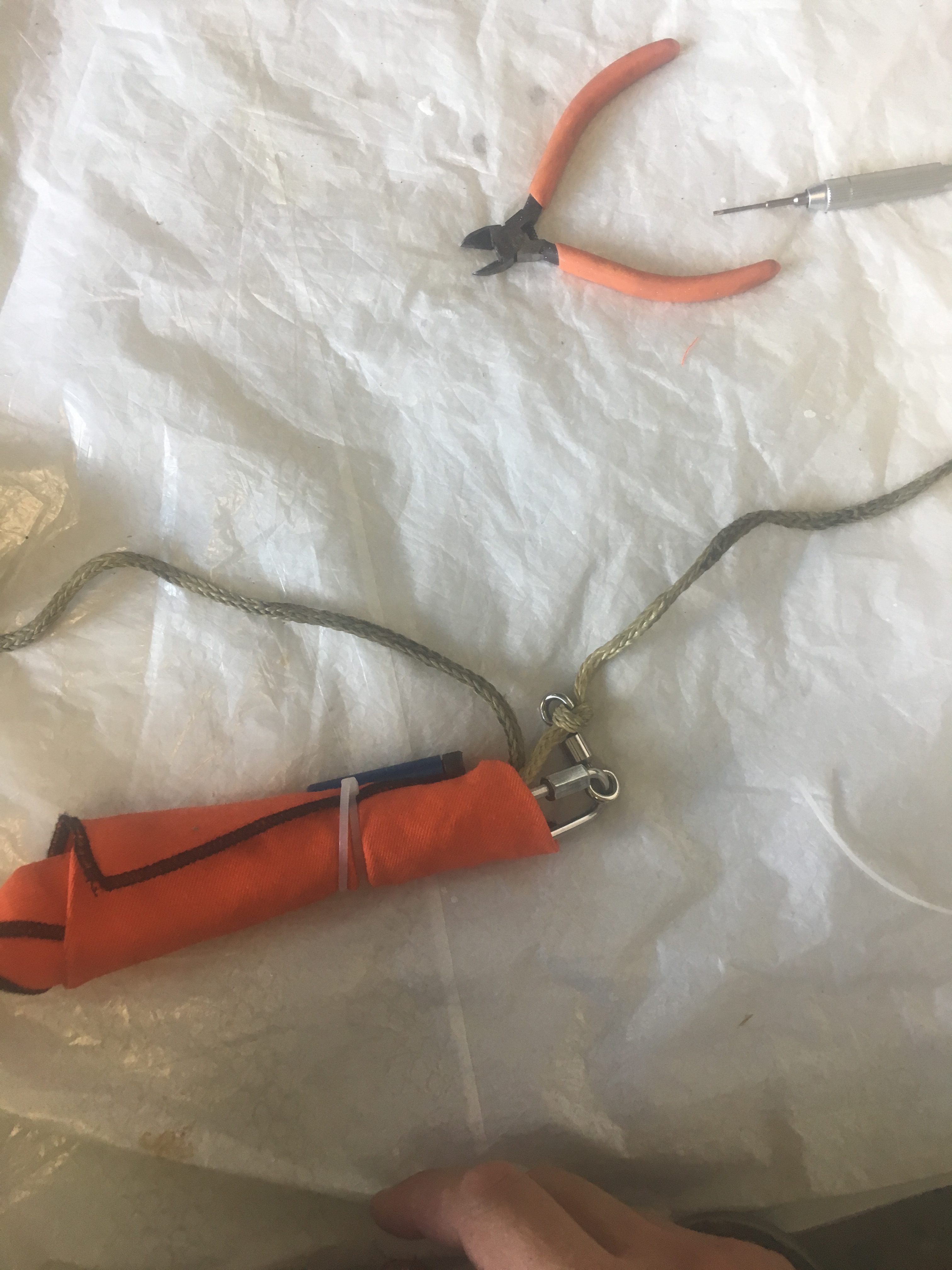
Pardon for lack of focus. Fold from RHS to about 1/3 way left.Fold bottom upFold Left piece to the right. The tightly role up.Place the Cable Cutter/cable Tie around it. Make sure the screw/end is at shroud end.
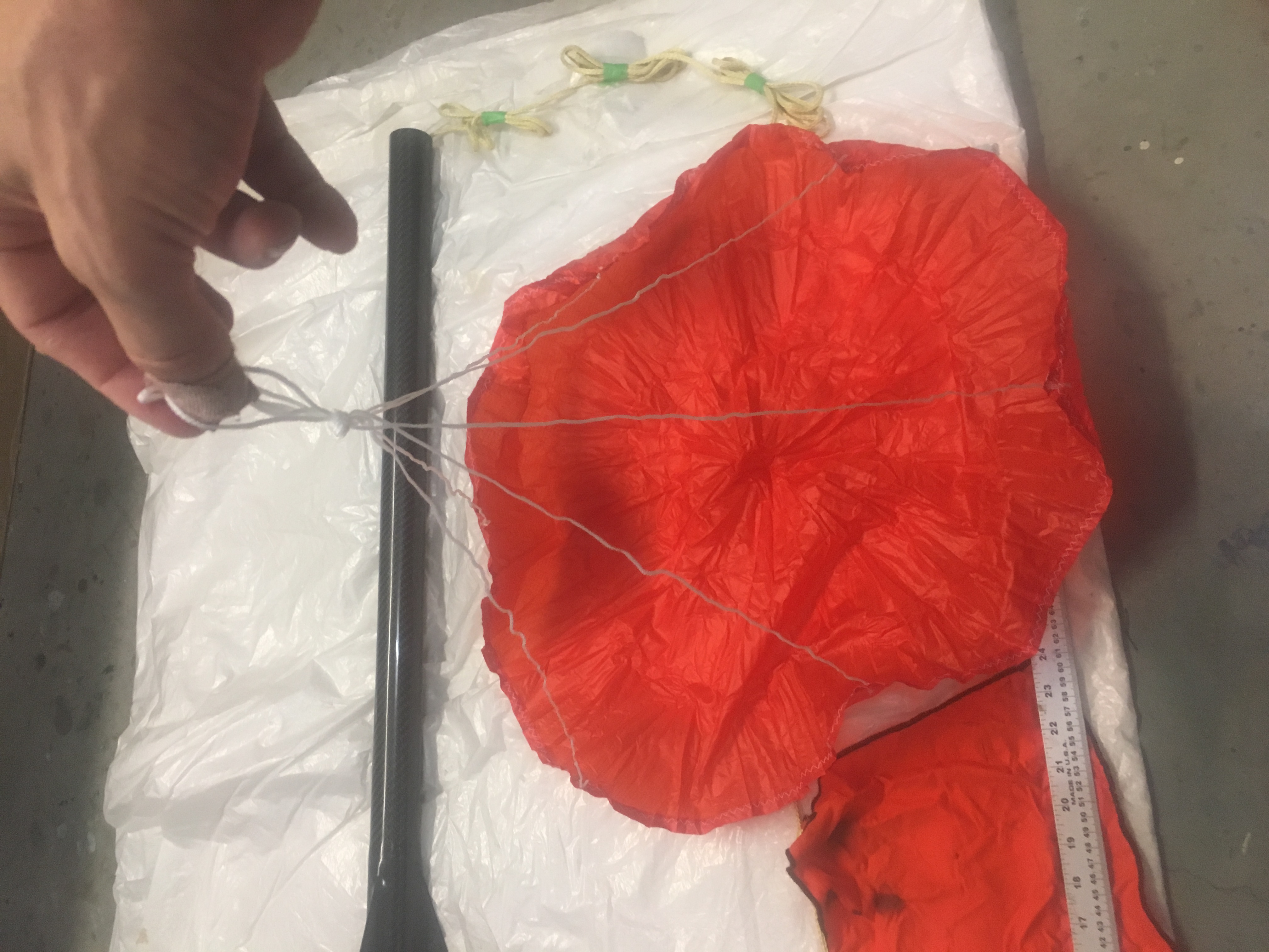
I made double sure that the parachute was attached to the shock-cord and the quick link was taped up.
Loading the recovery systems into the Air-frame.
Here are some photos of how I did it.
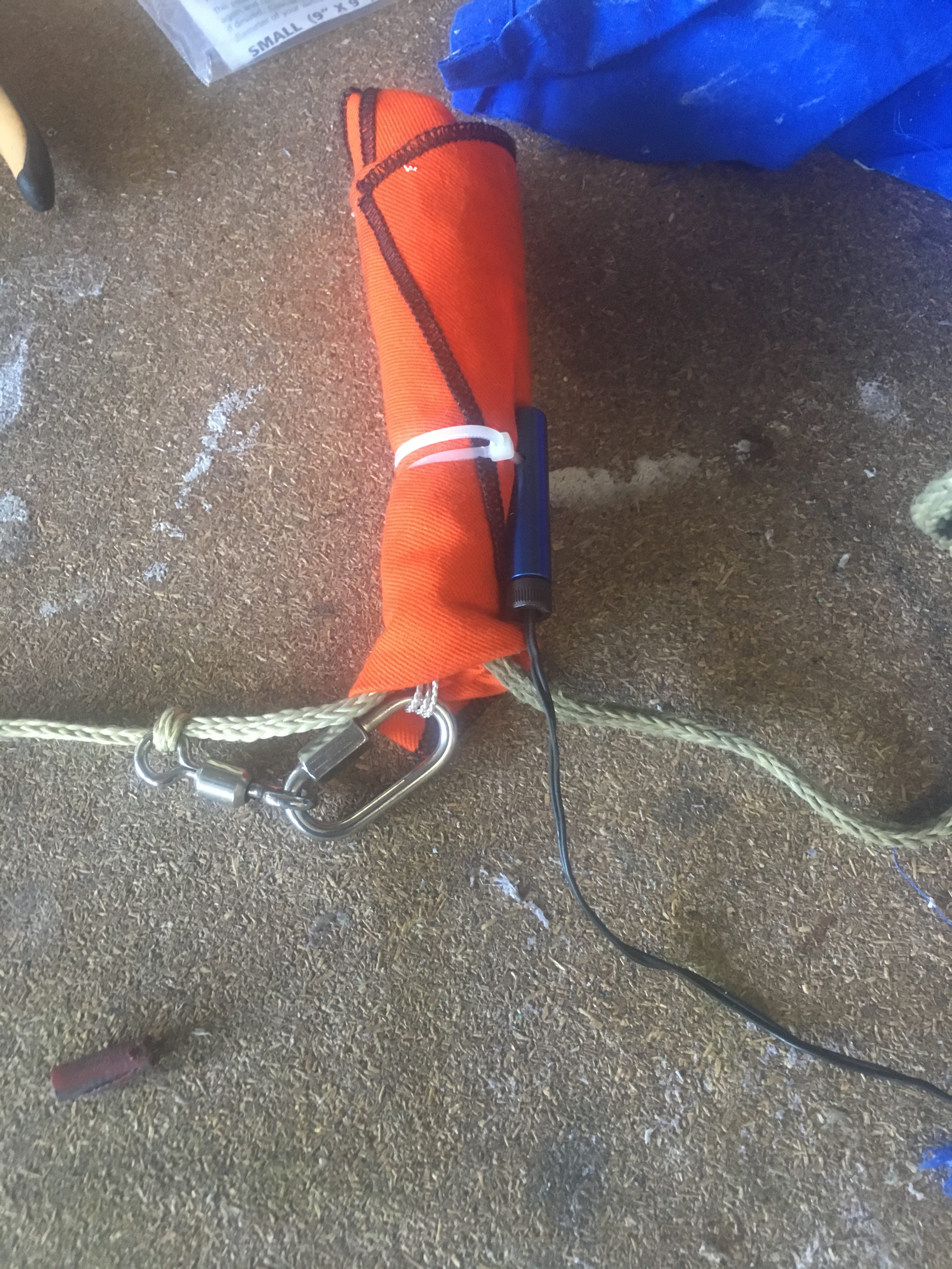
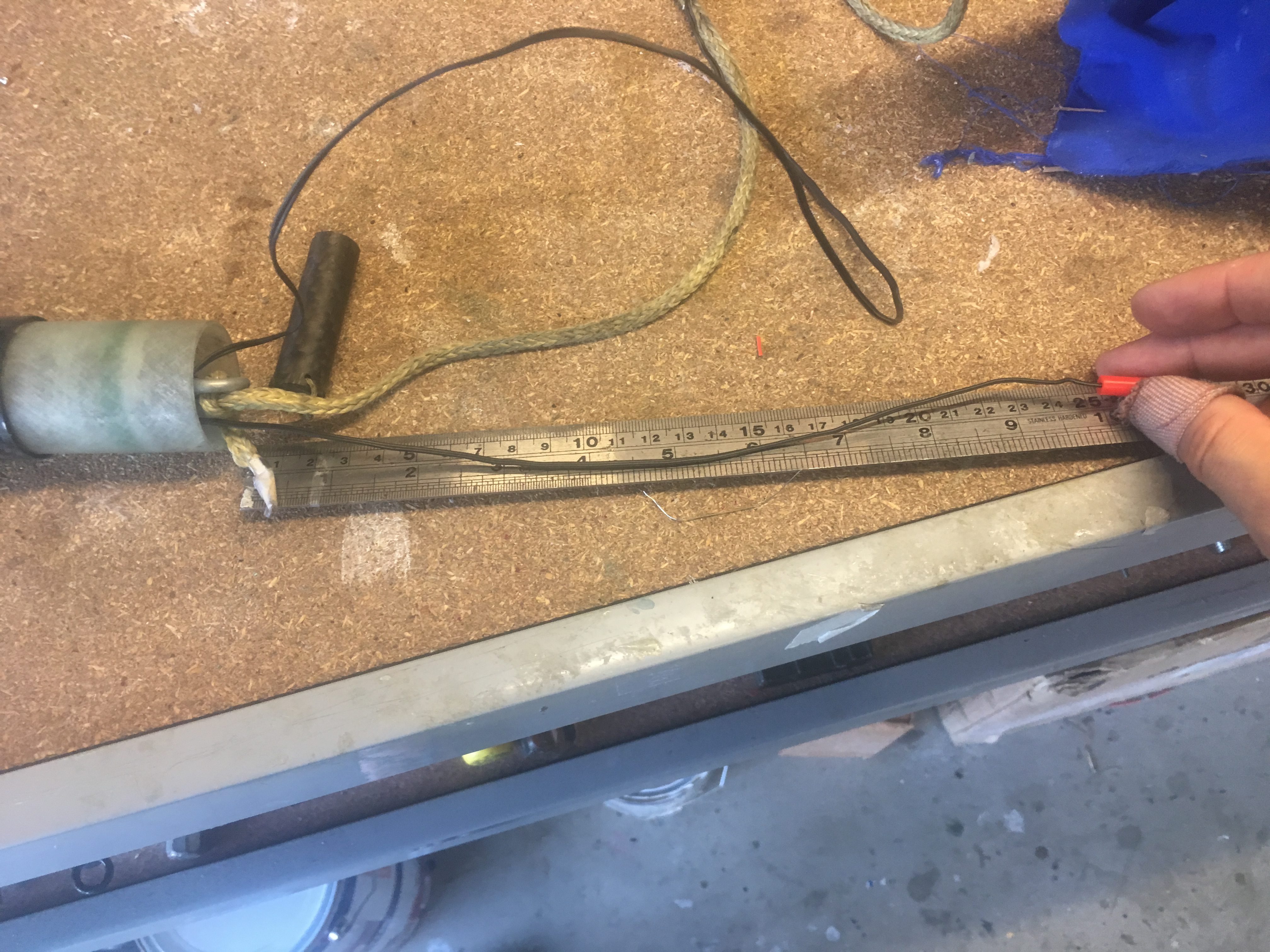
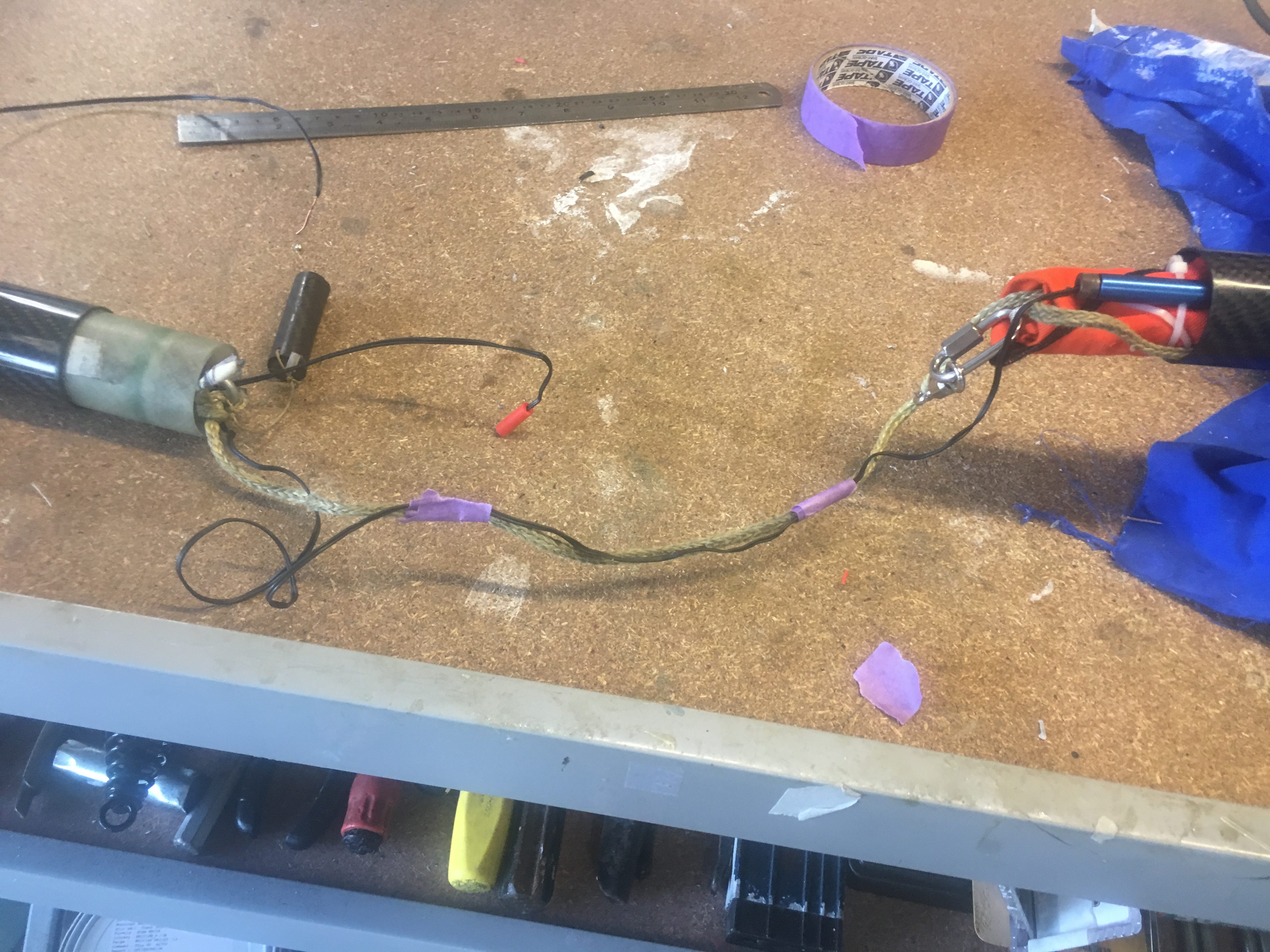
3rd test: Checking that there is chance of cable cutter migrating further away from the nose cone.3rd Test: Measuring length of igniter for Black Powder Charge well. Should be about 27cm.Determining any potential issues with igniters/charge well/shock cord.3rd Test: Tape igniter cable to shock cord, at two points with painting tape. Just trying to keep things orderly.3rd Test: Packing parachute bundle into air-frame.
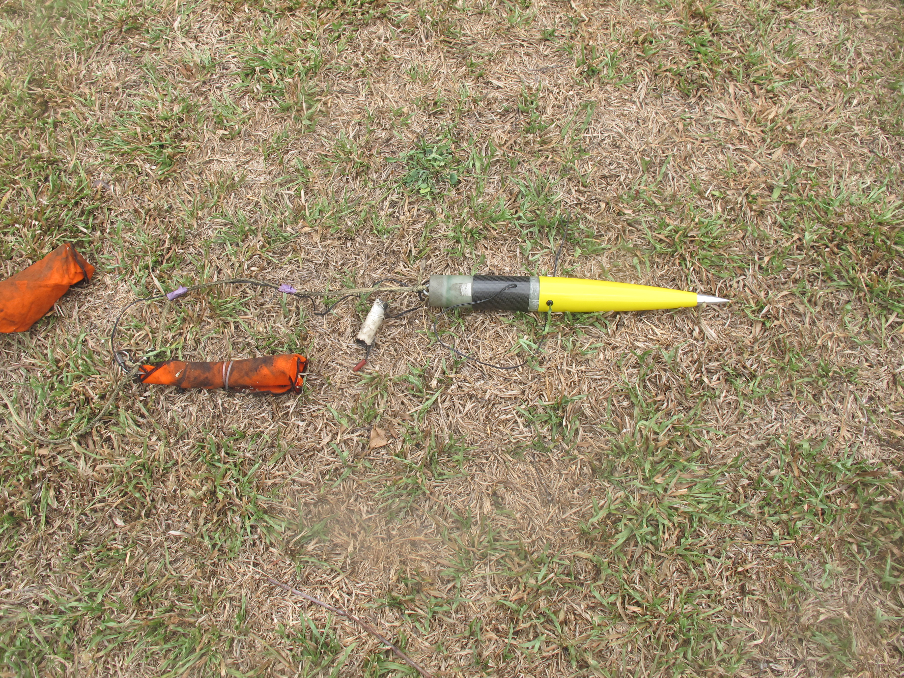
Results of the Ejection Test
After the test we observed:-
No tangles. Great!
One of the Z-folds opened up, two left to open up (This is good). The reason this is good is because we expect the load to be “fairly” significant when the parachute inflates and these Z-folds will help reduce load on the rocket components.
There was no damage to any component (though the charge well is showing some wear after three tests. It is still in good enough condition for use in launches.
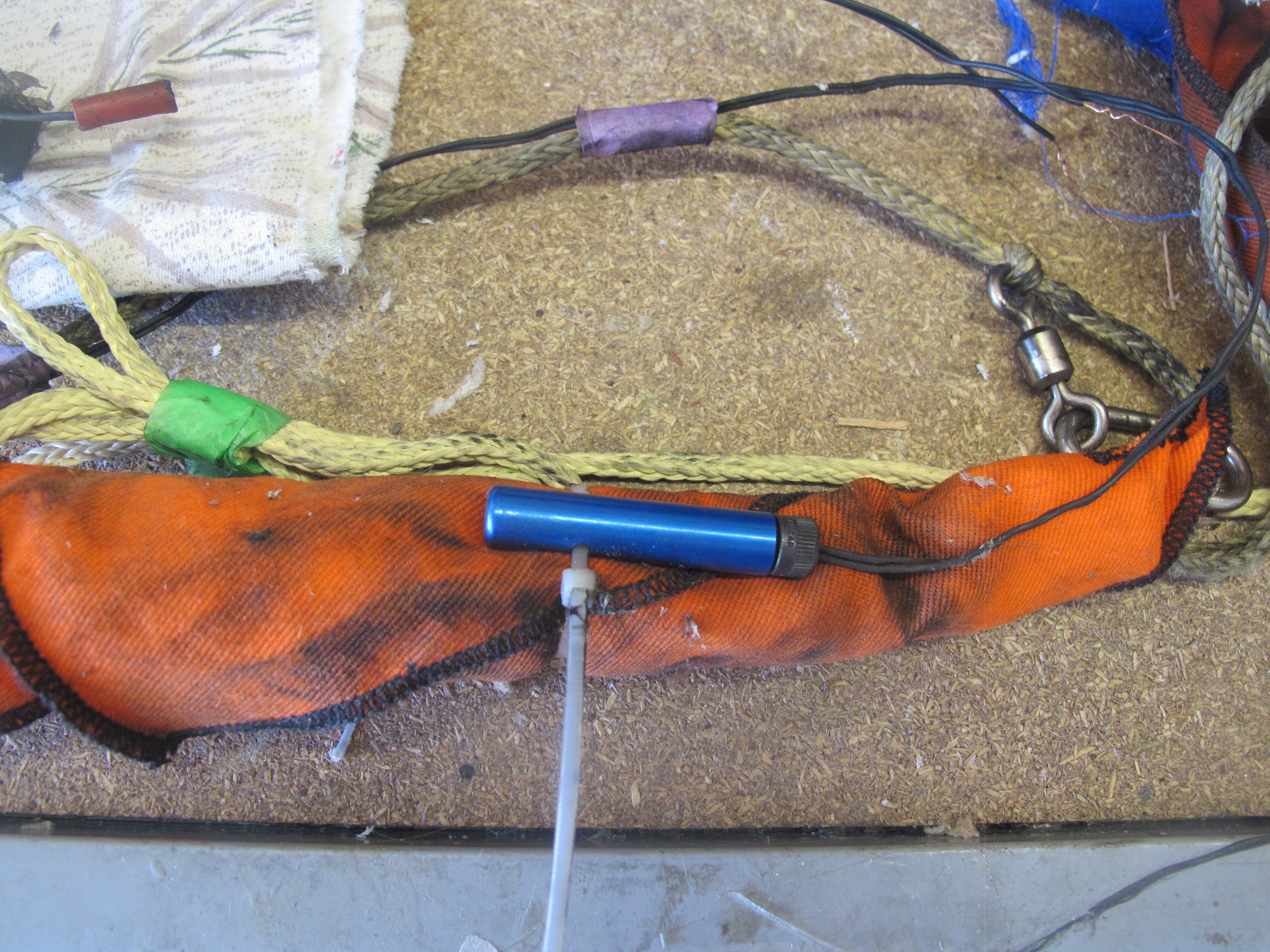
The Cable Cutter still attached to the parachute
The e-match wiring in-tact
Here are some photos and a movie.
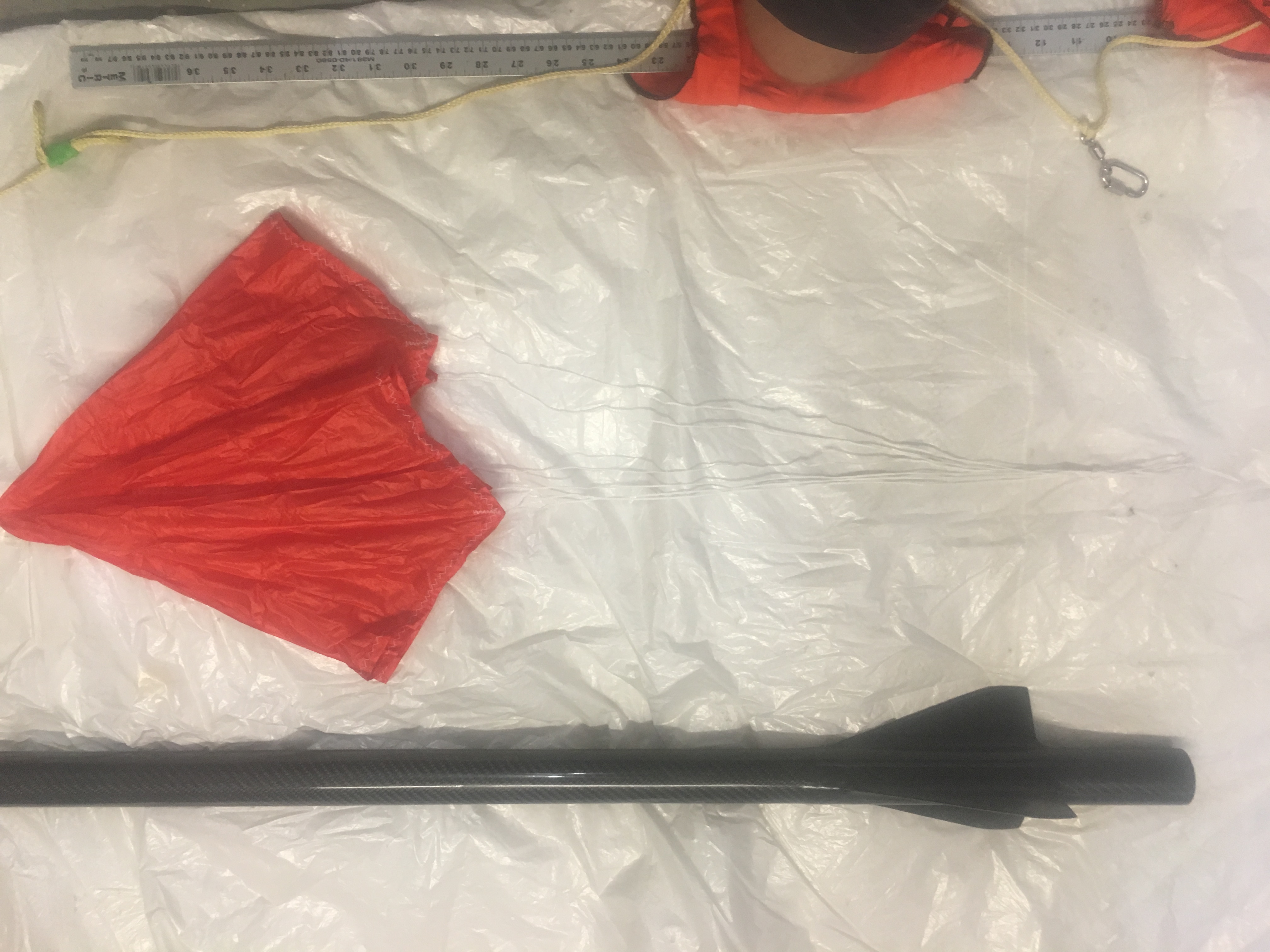
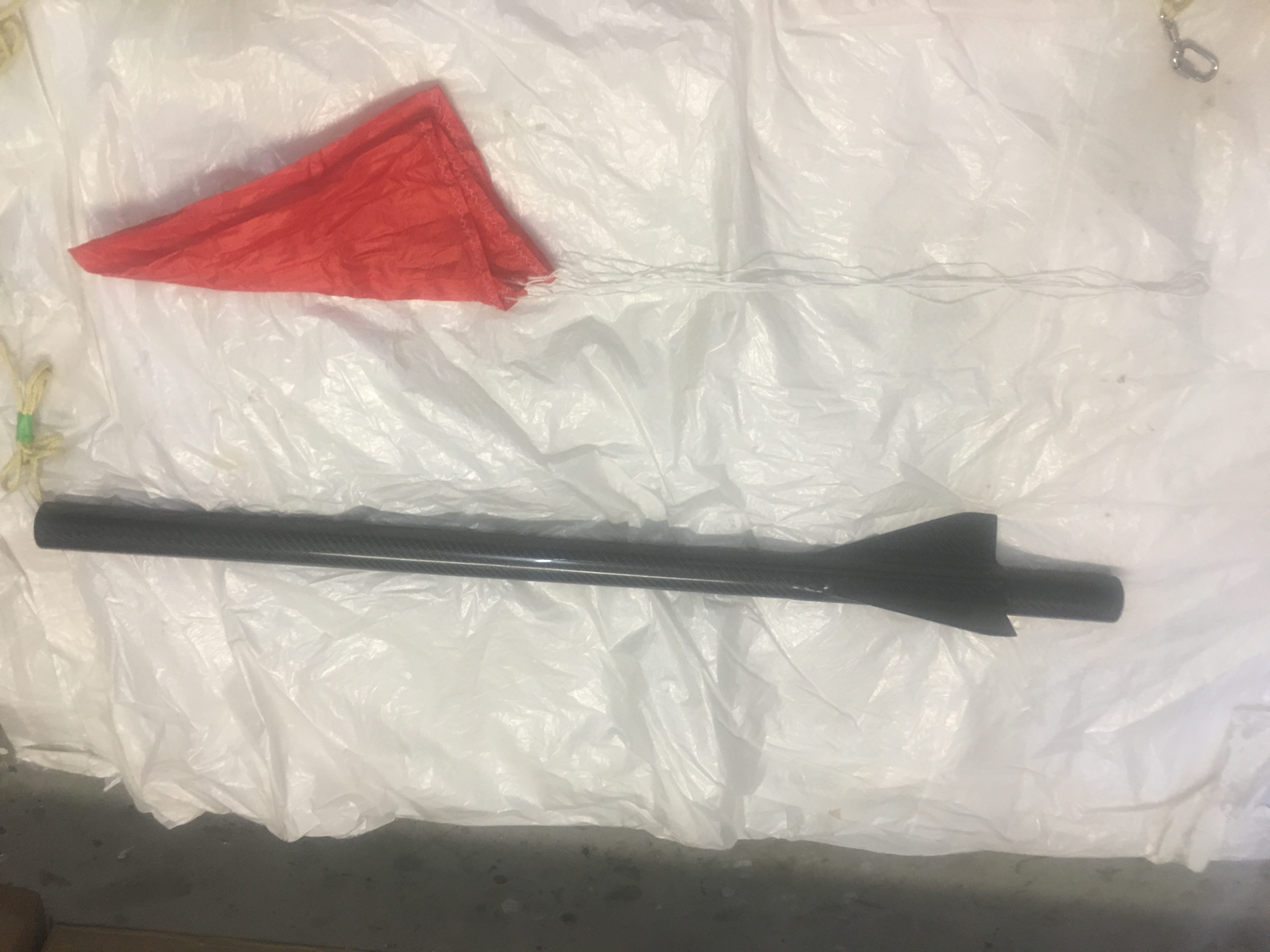
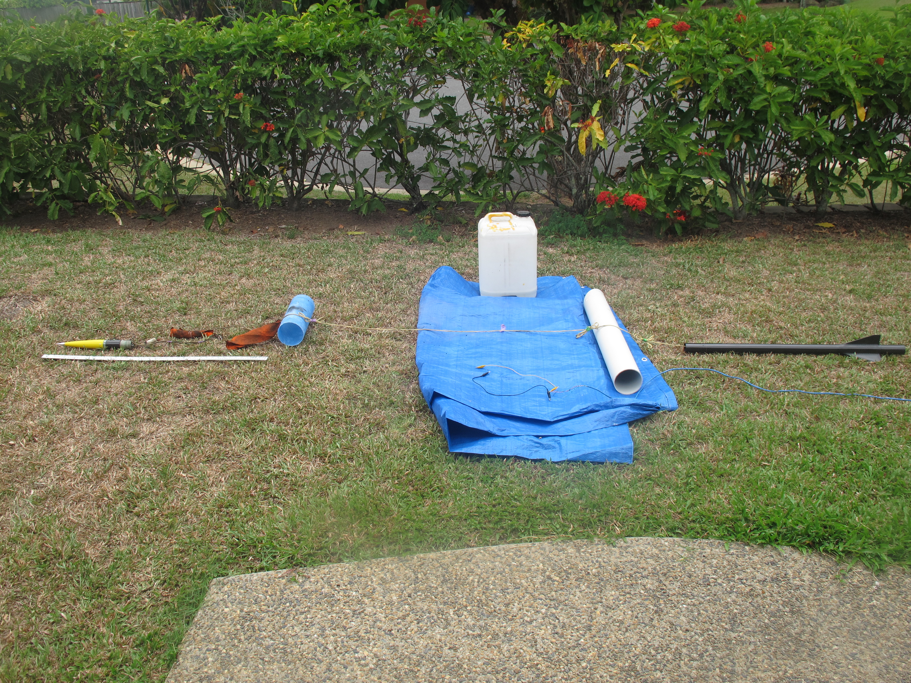
Showing off parts after ejection – side view. Take note of ruler.Inspection reveals no issues.Inspection reveals no issues.Inspection of nose cone end reveals no damage and cable cutter igniter intact. No tangles.Inspecting Cable Cutter and parachute/Nomex blanket. Seems to be intact.Inspecting parachute – no damage.
The recommended firing current is 1 Amp. The Duracell battery I want to use should be able to supply this without any trouble. I wish to conduct three tests:-
Test 1 – firing igniter standalone
Test 2 – Fire igniters from the Raven 3
Test 3 – Ejection test of drogue parachute.
Test 4 – Ejection test of main parachute.
To perform all these tests I created a test-fire box using old Cat-5 cable and some old parts lying around. Here is a movie describing what I made.
It isn’t neat/tidy, but very functional and safe. I can install all deployment charges without having the battery connected at all.
Test 1
I wanted to convince myself that the igniter would work on one of these nine volt batteries with this ignition system. Below is a video showing this.
The success of the flight is reliant upon the ejection charges separate the components and this this all depends upon the integrity of the Avionics installation.
For this reason, we review the Avionics bay to ensure that risks are identified and addressed. Some of these counter measures are shown in previous posts and no mention was made of how we arrived at the design here. We do this here.
Risks with Counter Measures
Switch Terminals
We were going to solder tips of wire and screw them into the terminals of the lever switch. When screwing them in, it tends to twist the entire wire around. This is probably “fine” but I can imagine that there is stress on the wire. The washer/screw should remain in place, but it is far from ideal.
So, what I did was get some very thin copper plate and cut out a small strip, 5mm x 10mm. Then I drilled a 3mm hole at one end. I sanded down the copper pieces of both sides and on curled one end (not the end with the hole) a little. Then I soldered a wire to the copper, leaving a small gap at the end with the hole (so I don’t add excessive thickness). At the other end, (the curled end), I applied 5 minute epoxy to the wire/insulation. This provides a very strong connector which won’t turn around when being attached to the switch and minimal strain is put on the wire strands! The copper is a great conductor and is very easy to solder to. Copper can also be bent to whatever shape is required.
Below is a picture as it might be hard to visualize it from the description above.
Copper connector attached to switch
The curl is intentional. It reduces chance of wire rubbing against sharp edge.
Screws
Screws can rattle undone, so I applied LocTite equivalent to all screws. This includes:-
Bulkhead powder wells (PVC caps)
Bulkhead terminal blocks
Raven 3 PCB screws
Screw holding the switch right-angle
Screws holding the 3 x 2 black terminal block
Glue to some components
A lot of the components that are attached only have one screw. They are tightened a lot, but there is always the risk they could loosen/rotate. To reduce the chance of this, I applied a few drops of CA glue to them. The parts that had this done were:-
Bulkhead powder wells (PVC caps)
Bulkhead terminal blocks
MicroSwitch right-angle aluminium piece
Nine Volt battery Clip
I was concerned that the 9 volt battery clip was not of sufficiently strong construction and the clip I used was recycled from another project. So what I did was purchase a replacement one from Jaycar.
Tough 9-volt battery clip
I was also concerned about the red/black wires getting into places they shouldn’t so I :-
Cut the black wire to a length that meant it couldn’t possibly be a problem
Applied small drops of CA glue to the red wire where I wanted it to rest, just to encourage it to stay there. It may come of in flight, but its insignificant weight means it should be okay.
The Dean-Plug
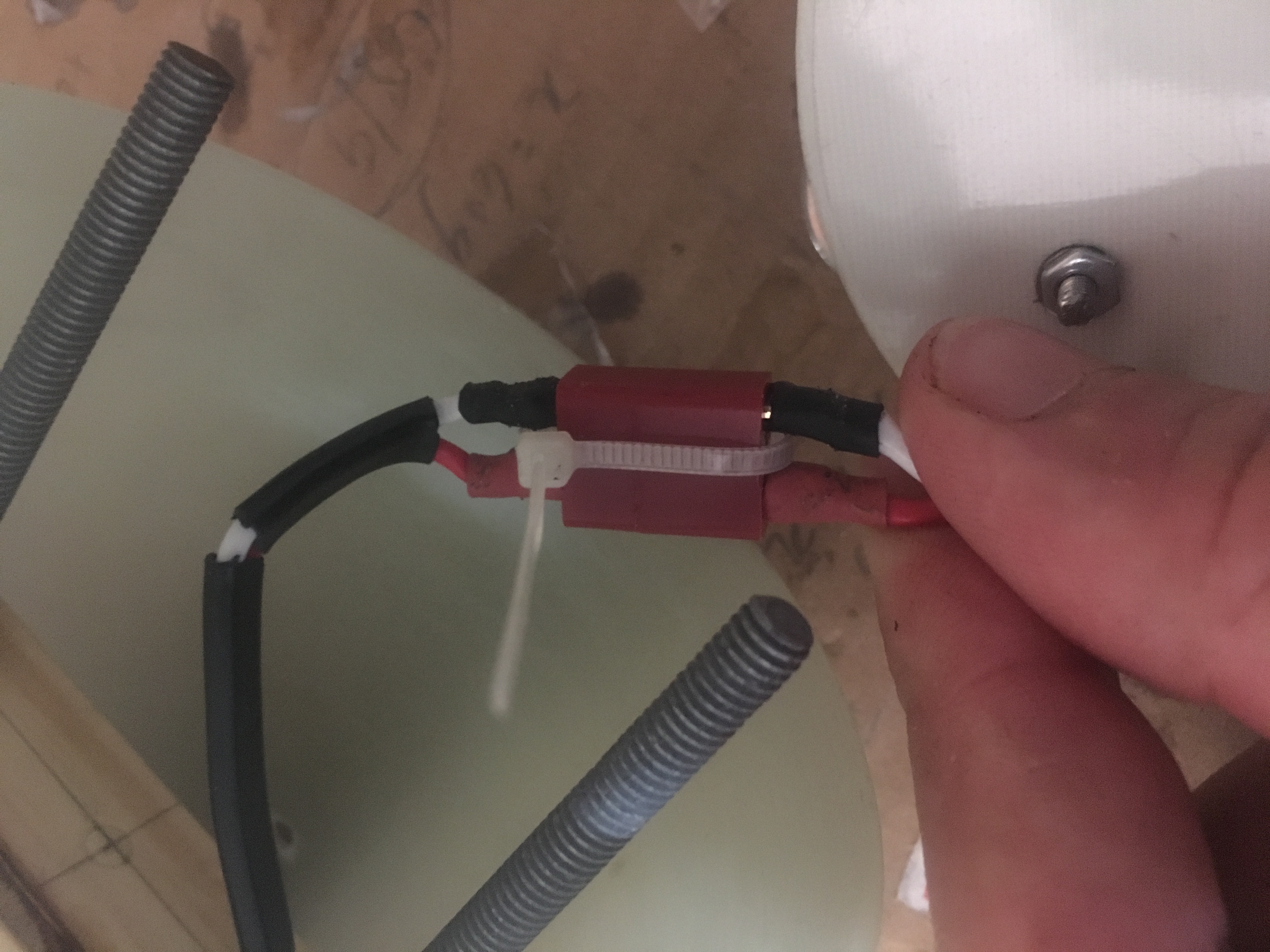
I wanted to ensure that Dean-Plug would not separate in flight. So I will install a small cable tie as shown below.
Cable-tie to keep dean-plug attached.
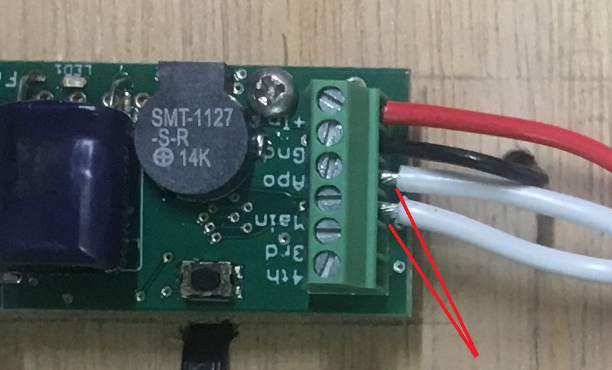
Wires into Raven3
I removed a little more insulation then i should have on some of the wires that are screwed into the Terminal block on the Raven 3. As a consequences, some of the wire was visible. While it is extremely unlikely that we could have some short, I decided to cut the wire a little, to reduce the amount of bare wire showing. See the picture below.
Photo showing bare wire showing.
It is also about taking pride in the work that I do; keeping it look good as well.
SuperCap on Raven3
It is recommended that the SuperCap be glued down if the rocket is going experience high-G flights. My first flight of this rocket will not involve high-G’s, but subsequent flights may. Following instructions, I decided to apply a drop of Epoxy under the capacitor.