Category Archives: Planning

Performing Ejection Tests

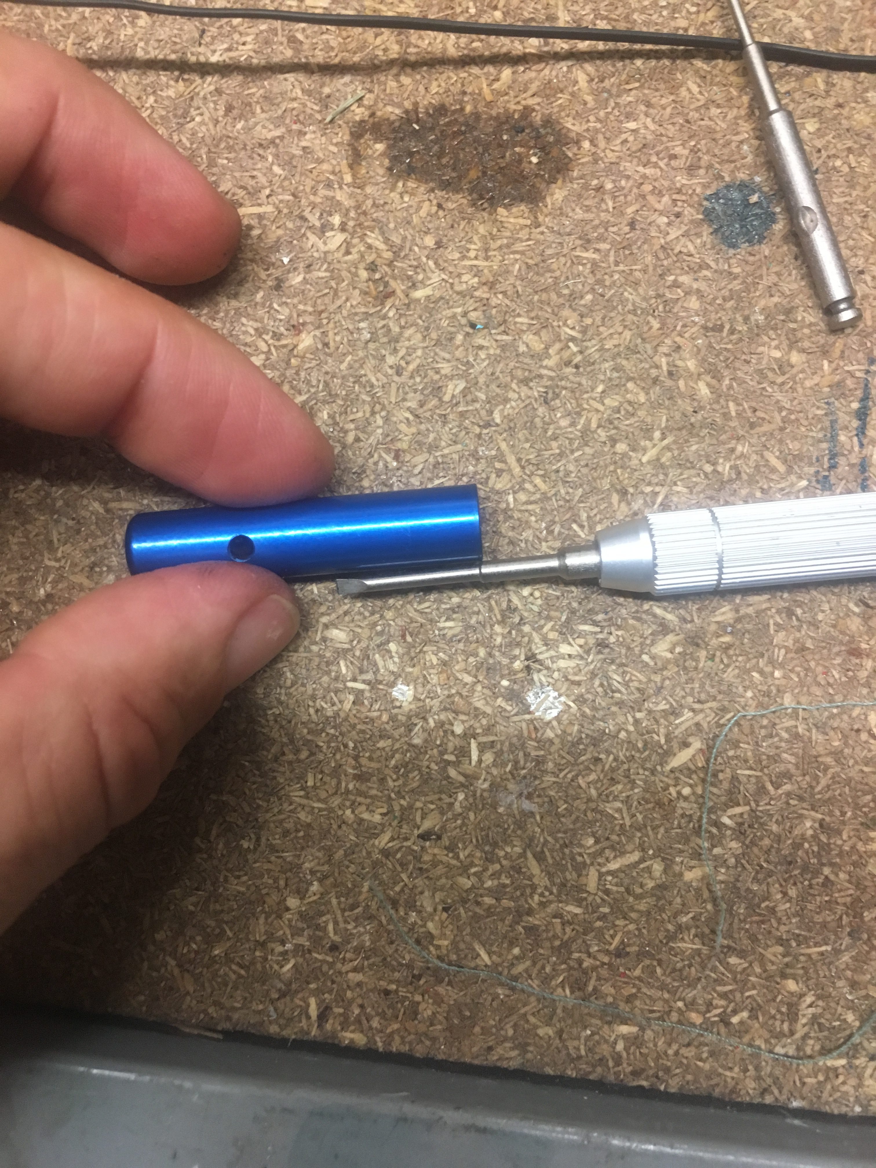
38mm CTI and AeroPak motors come buy default with approx 1.4 grams of Black Powder for their ejection charges. Based on this and the fact my rocket has half of volume blocked off by engine block, I decided to start my ejection charge tests at 0.75 grams. Ultimately I got up to 1.76 grams of BP. This post discusses this in detail.


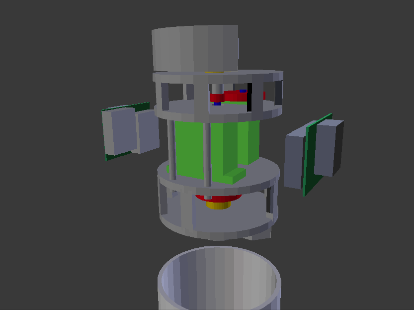
How the system is packed.

This is probably the best place to describe how the recovery system was packed, because the tests identified a possible issue with the set-up.

View of all the components to be packed into air-frame - prior to folding and attaching igniters, cable cutter.
View of all the components to be packed into air-frame – prior to folding and attaching igniters, cable cutter.

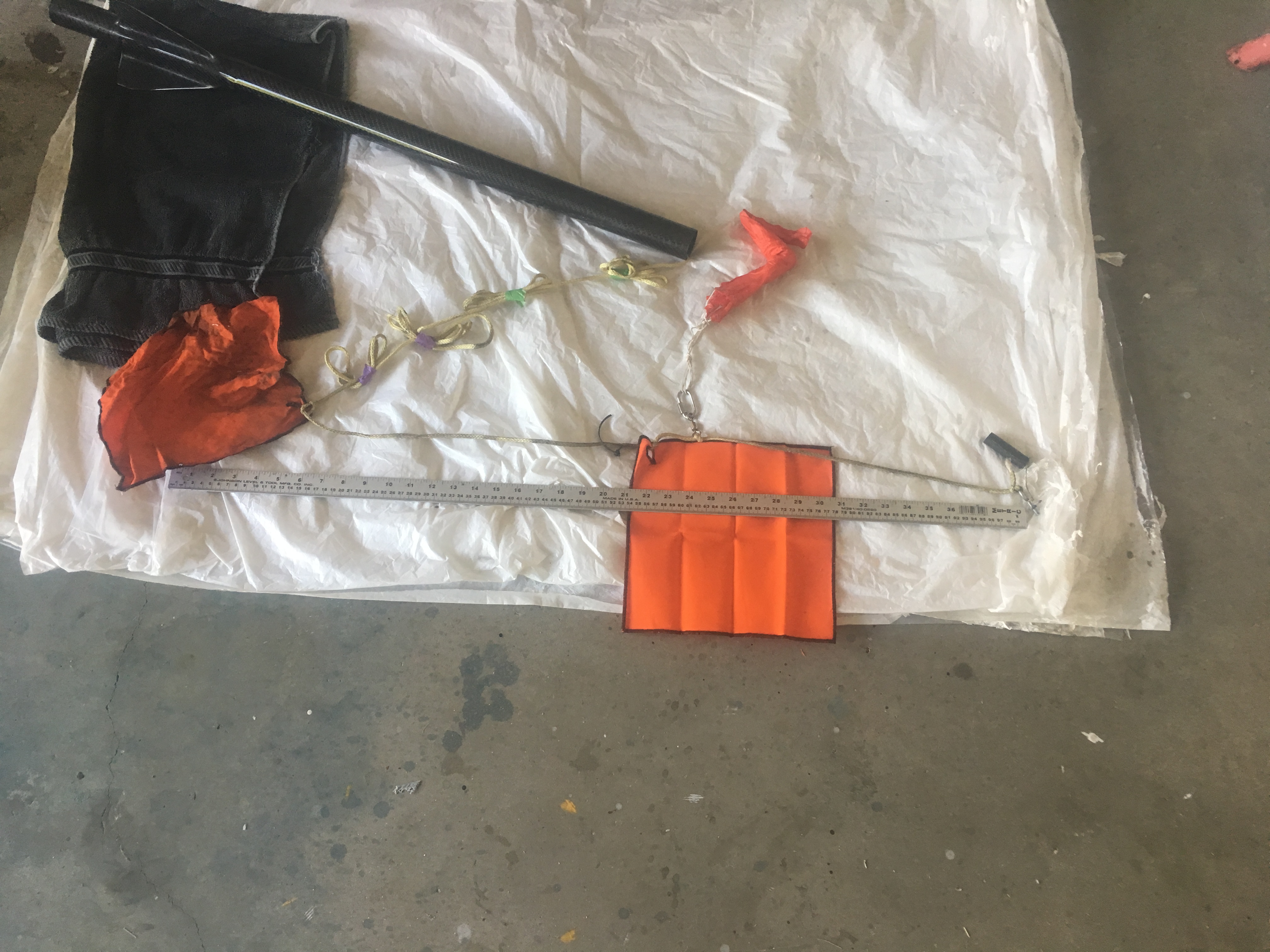
You will notice in this photo there are TWO Nomex blankets. The left one  covers the shock-cord (but its primary purpose is add additional drag) and the other Nomex blank protects the parachute. The right Nomex blanket is held in place with a Cable Cutter, the right is simply wrapped into a bundle.

The parachute is on a Swivel and uses a 4mm Quick-Link. The Shock-cord is 5 metres in length, with 0.5 meters inside the air-frame. Notice the use of Z-Folds.


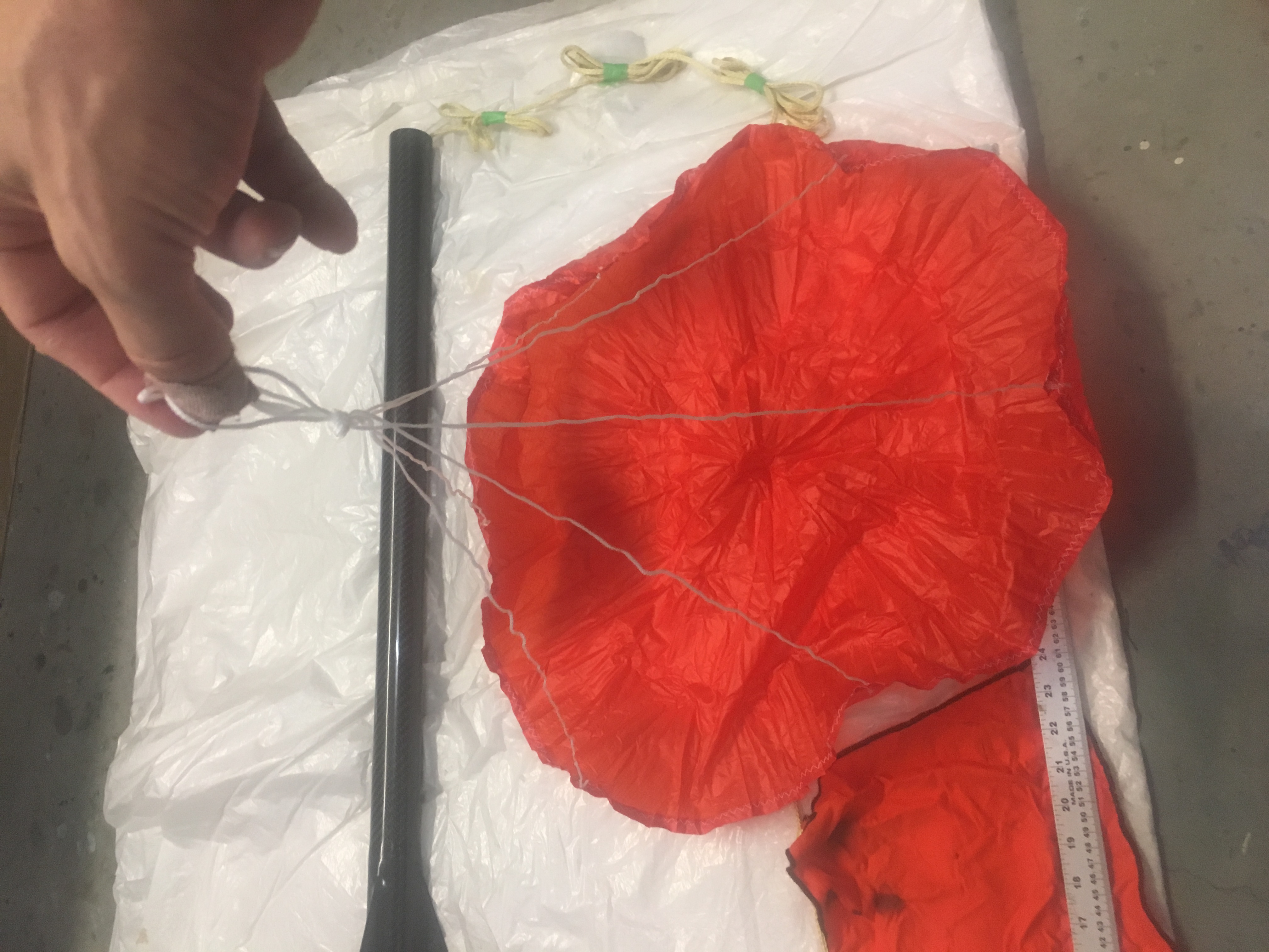
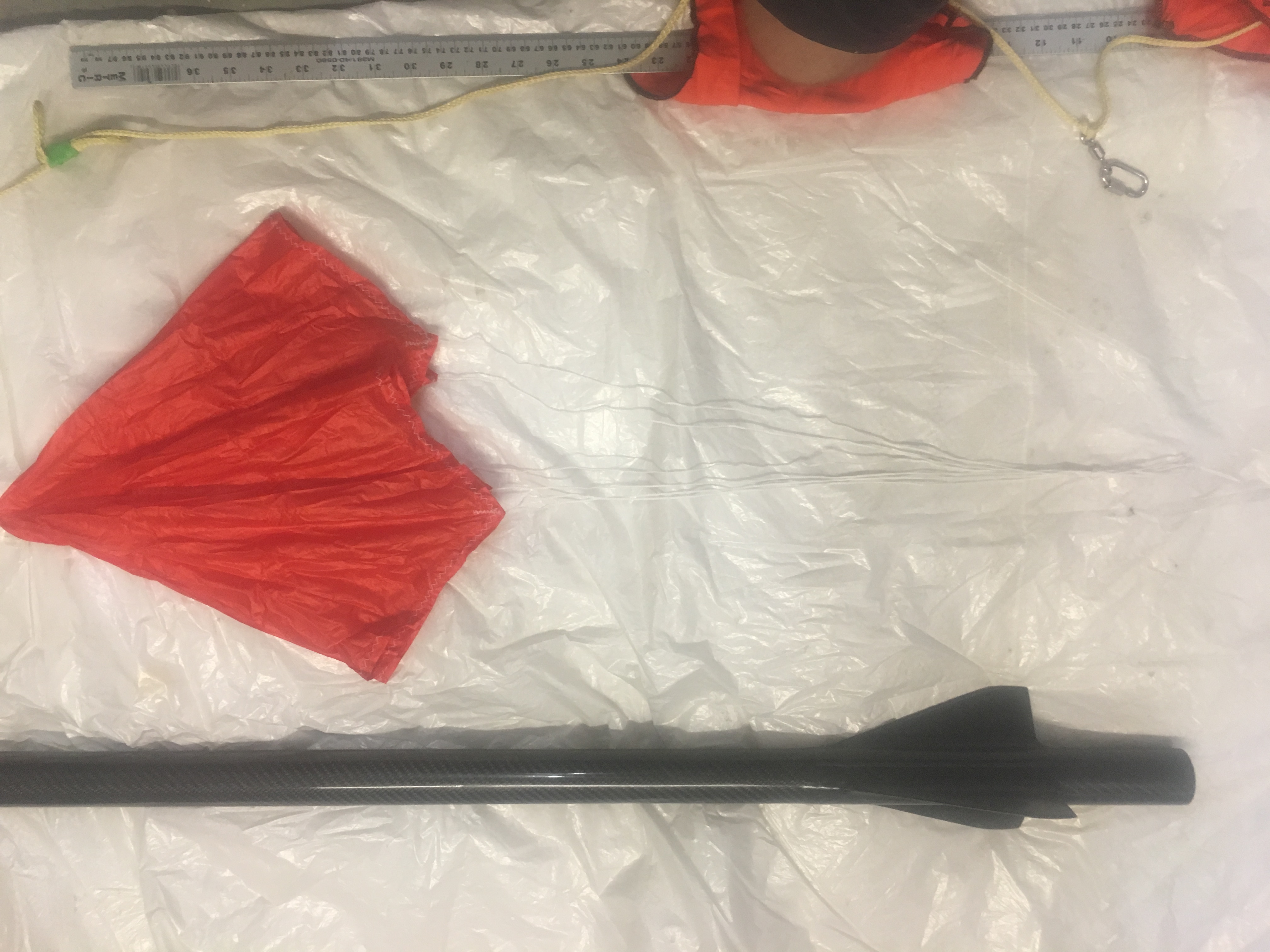
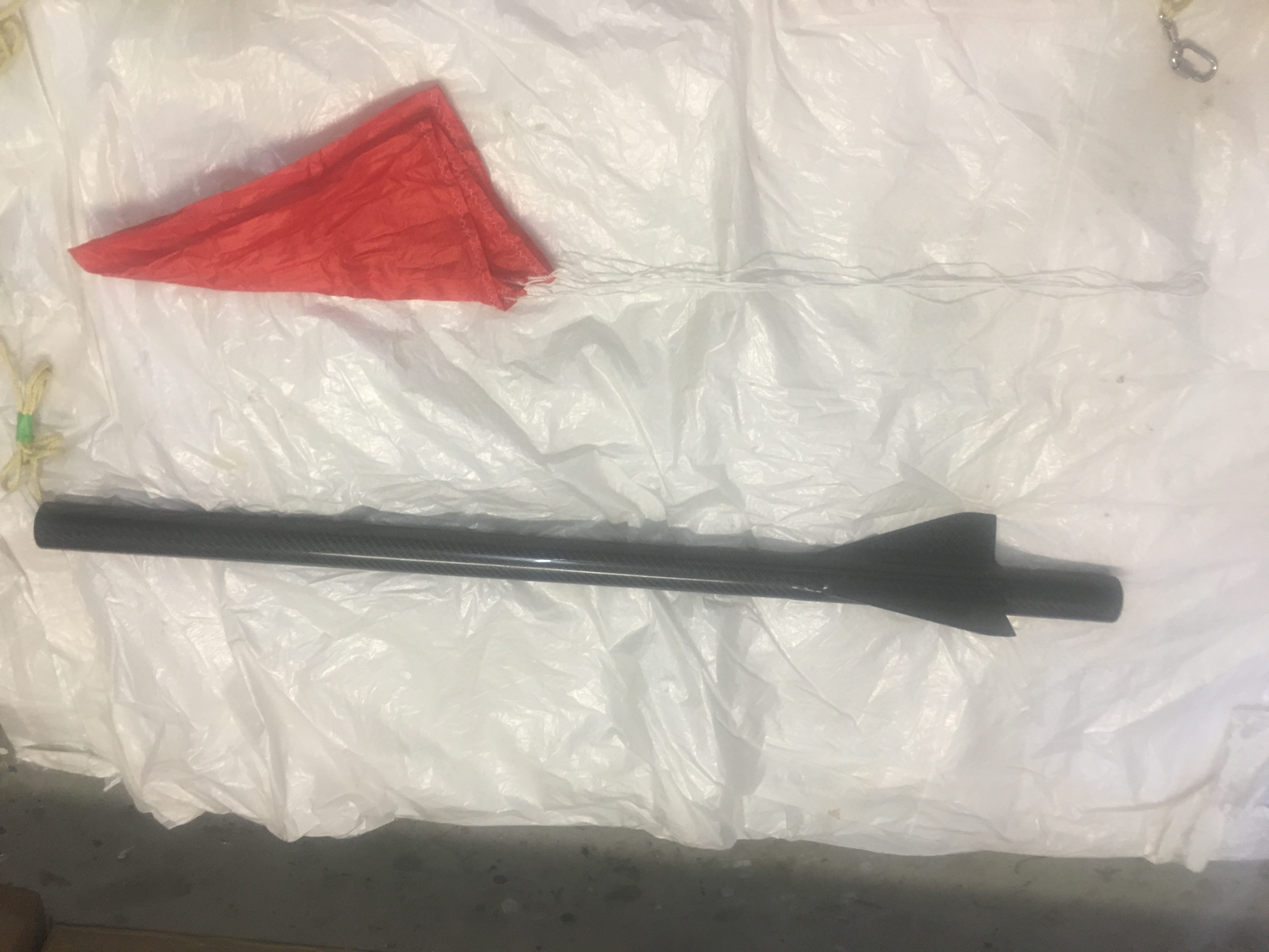
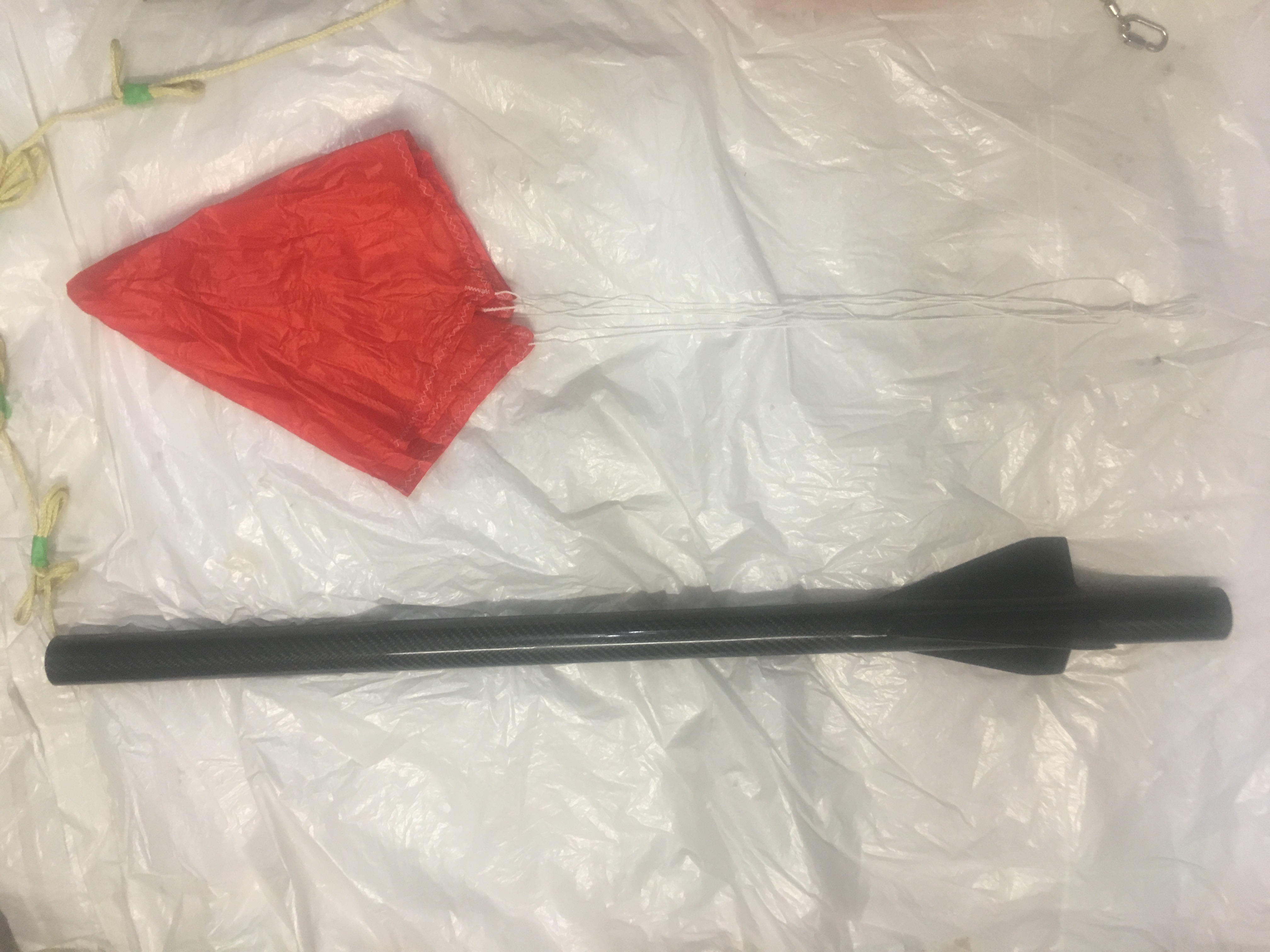
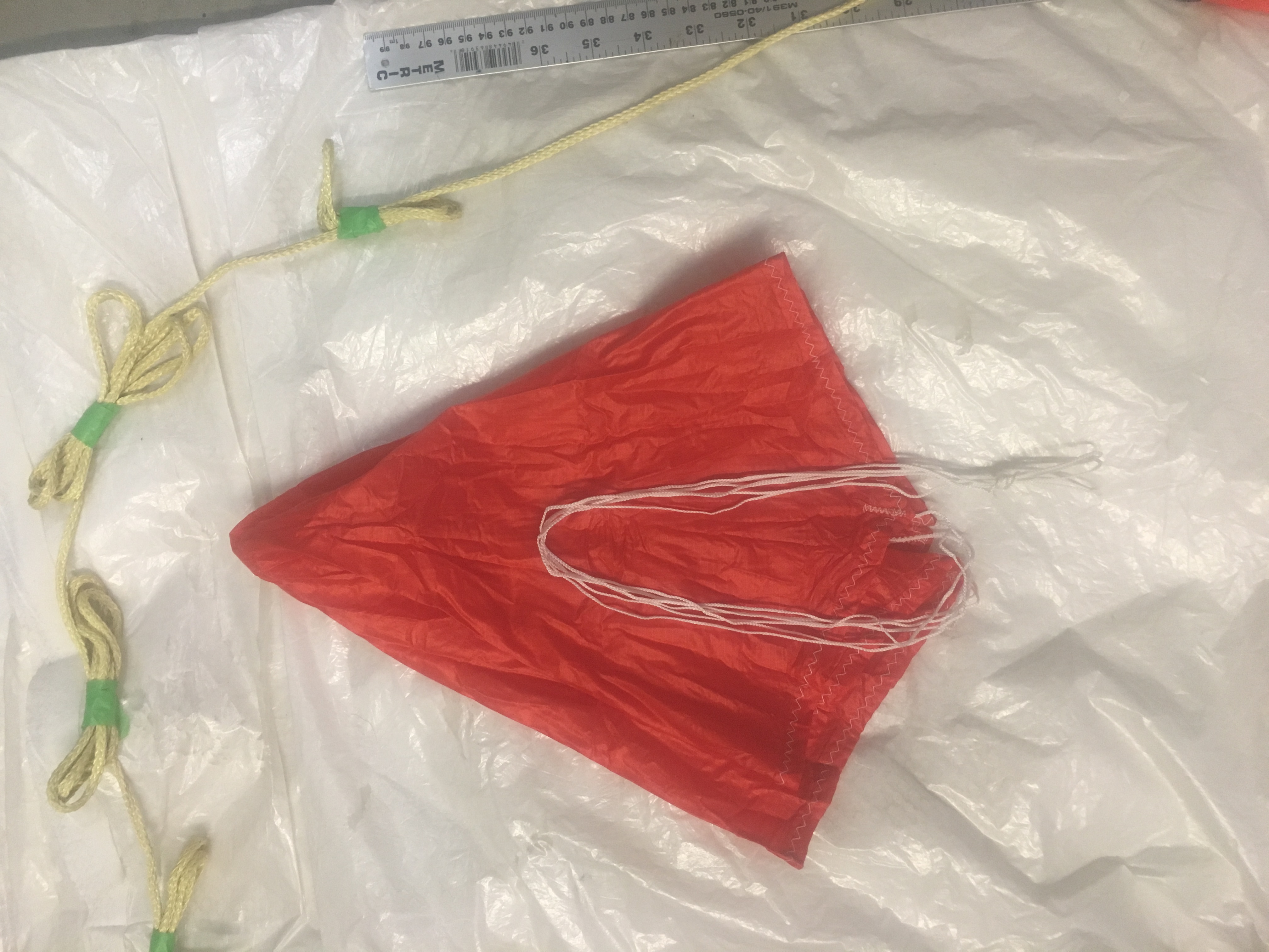
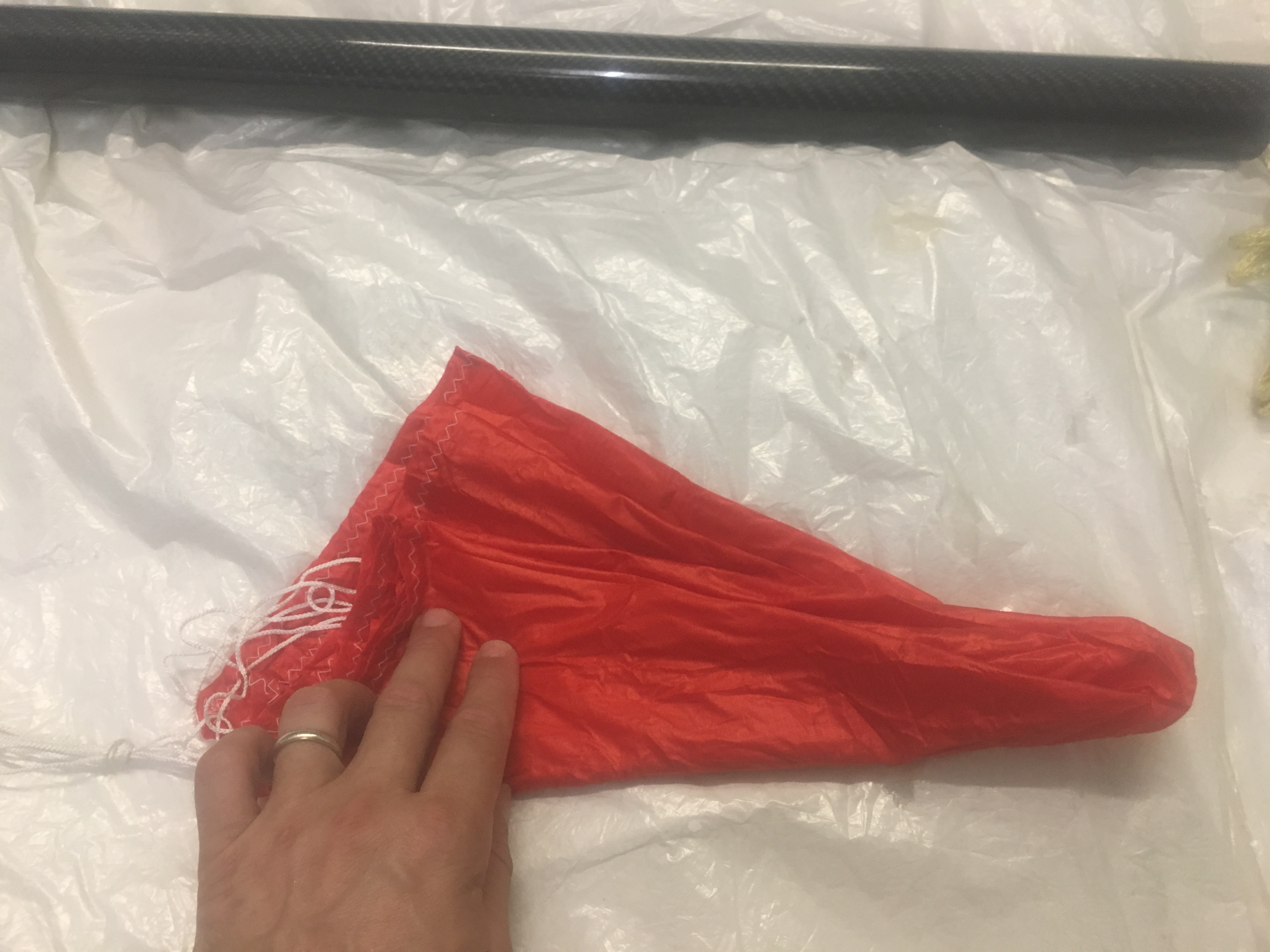
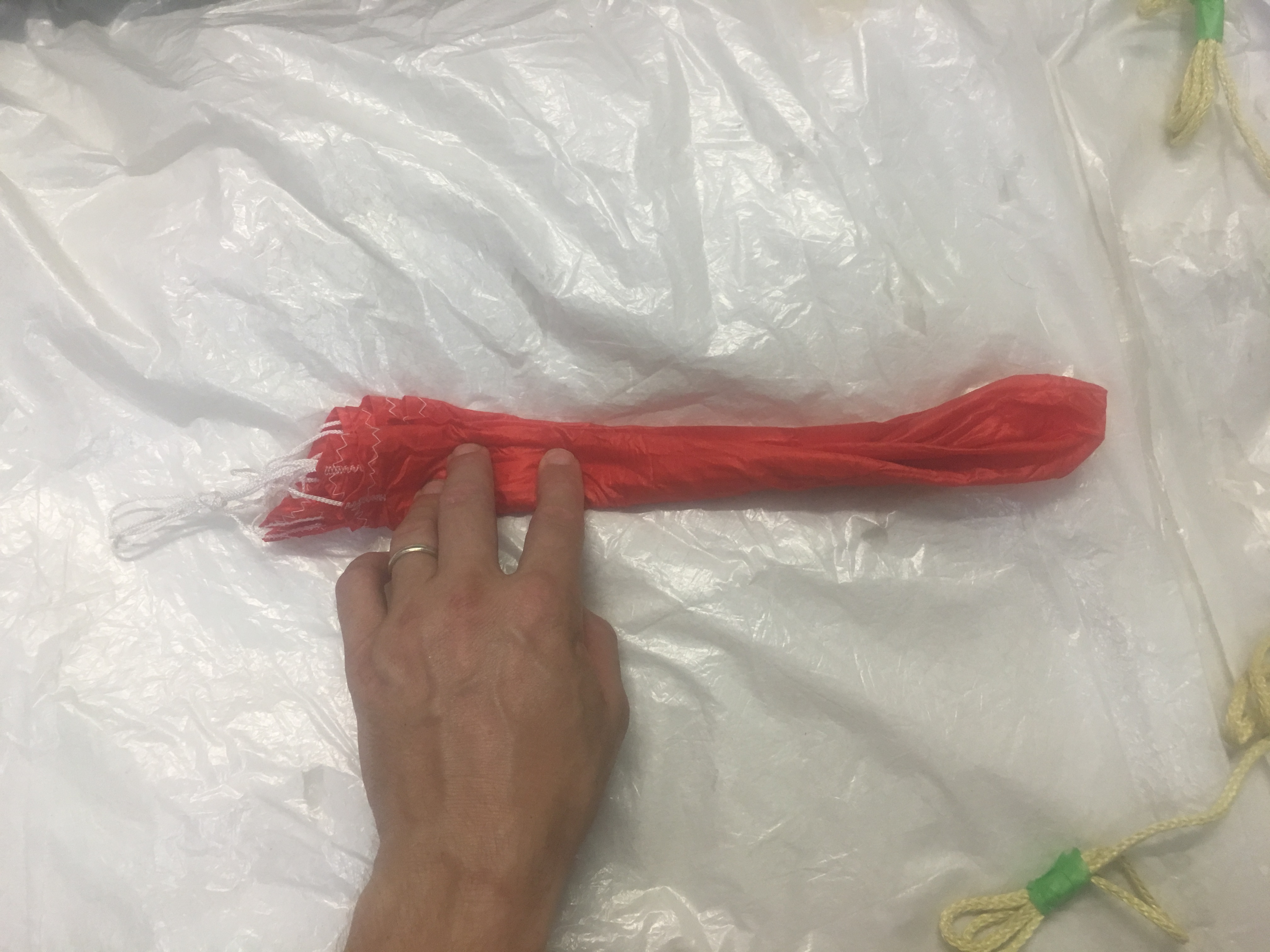
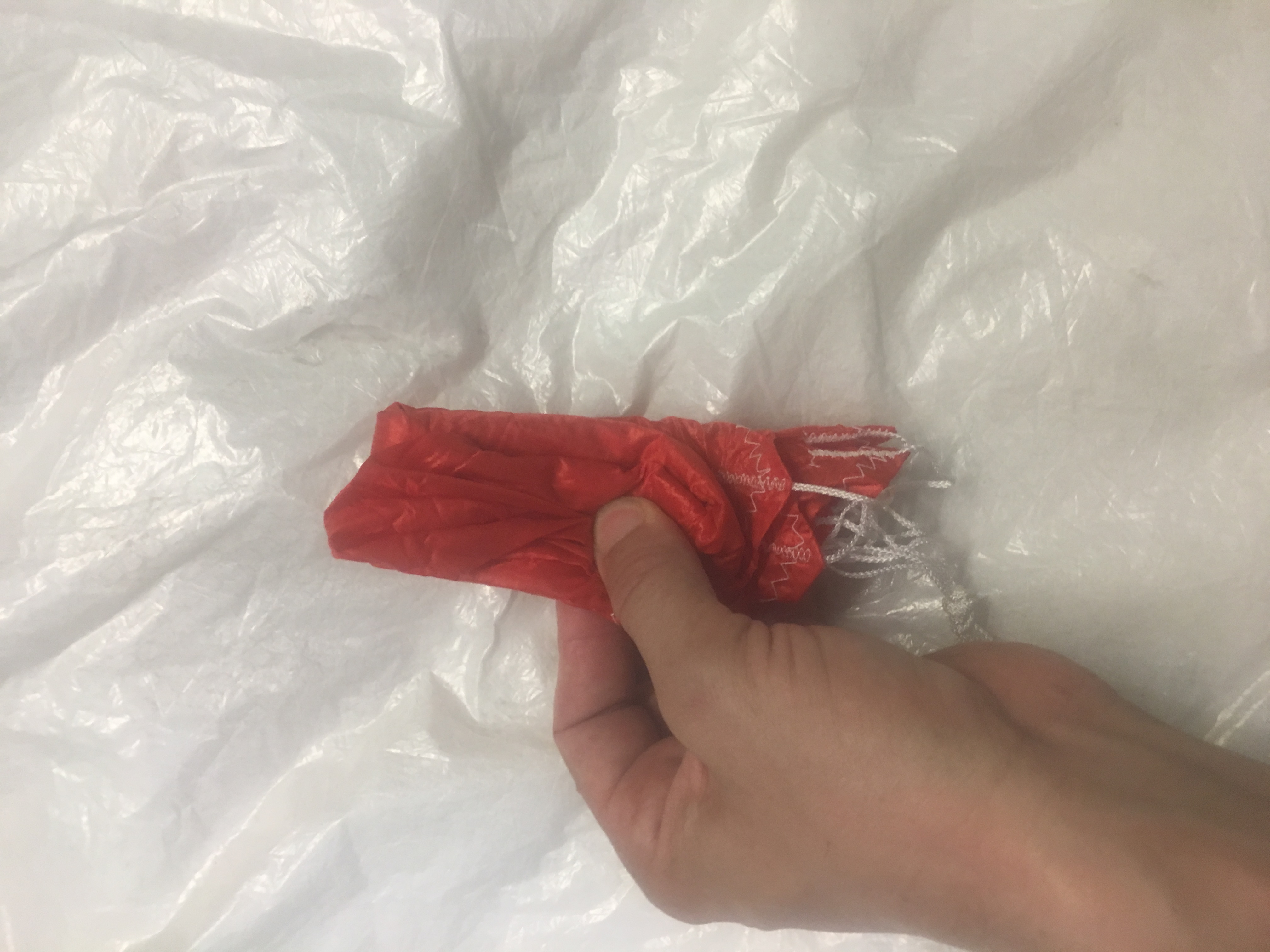
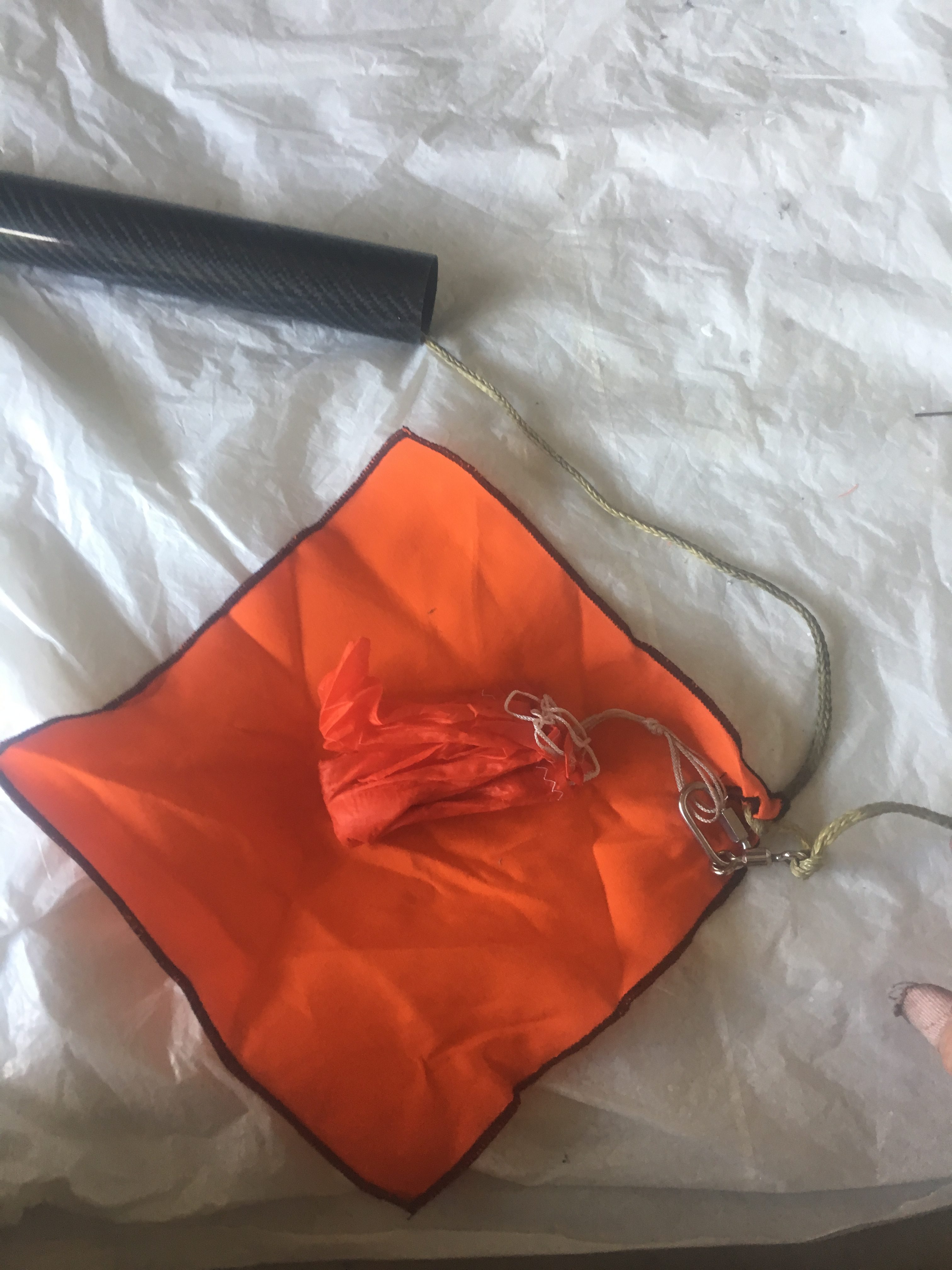
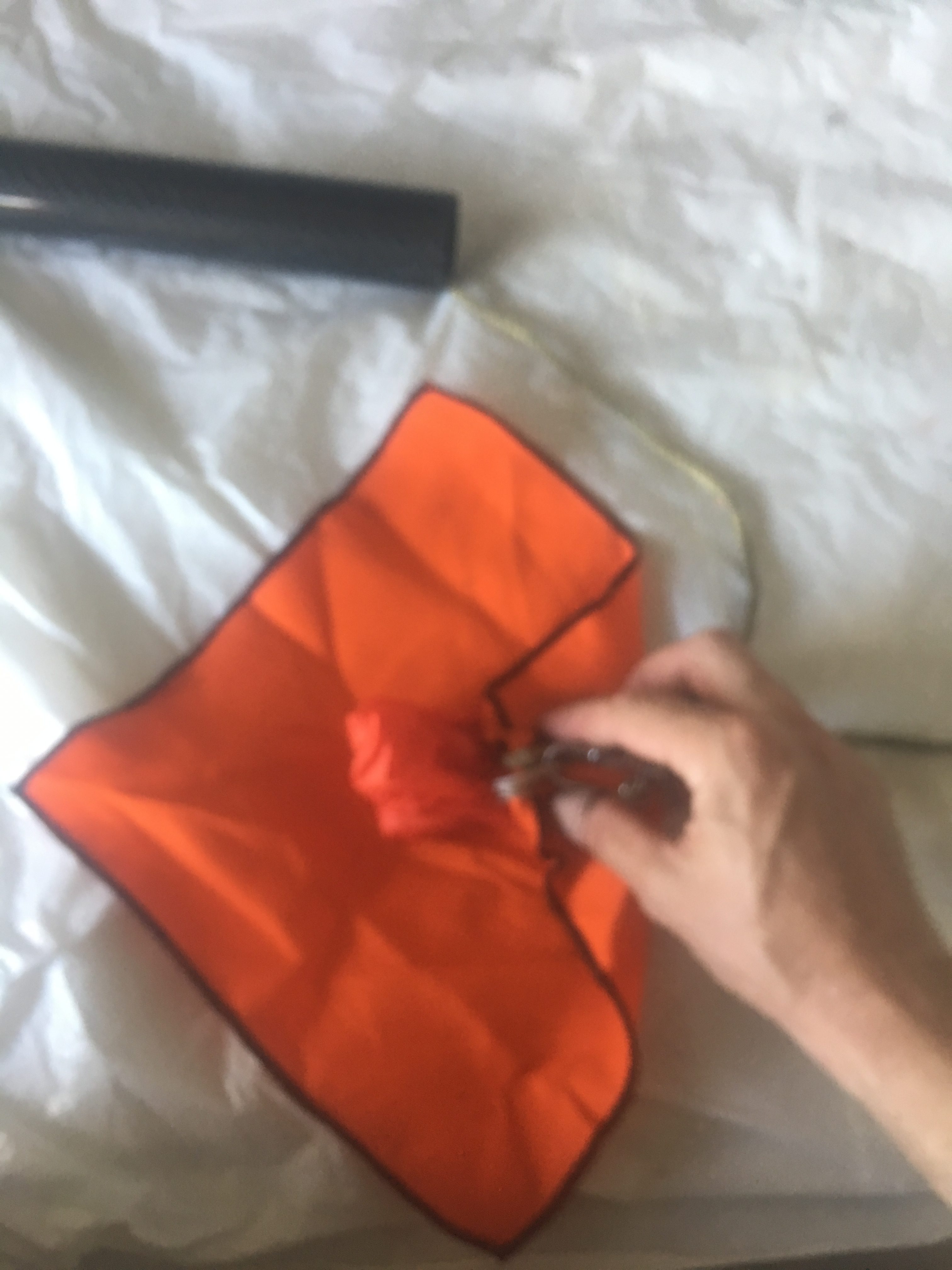
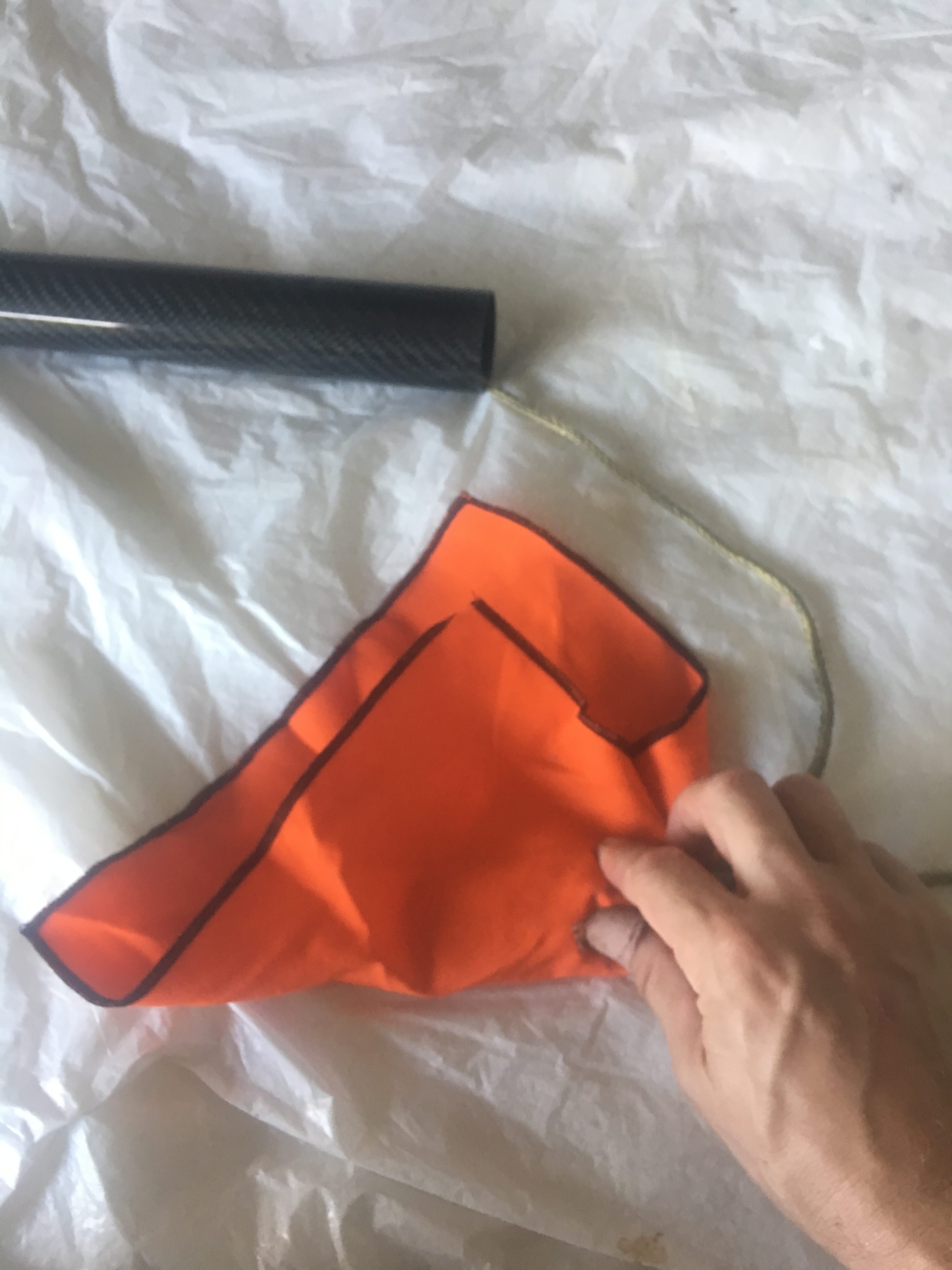
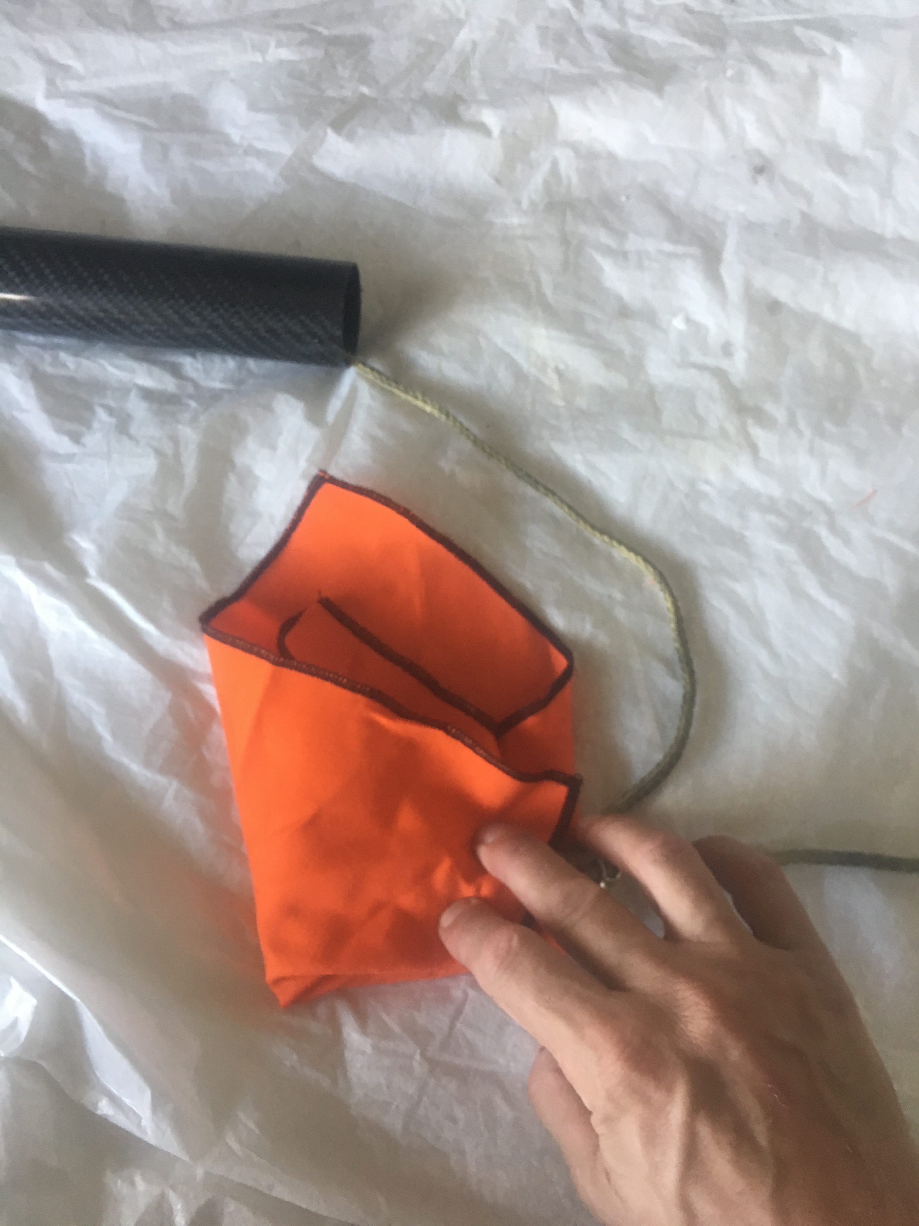
How the Parachute is folded

Here are some photos of how it was folded.

Making sure parachute has no damage and shroud lines are not tangled.
Laying out the parachute, shroud lines taut.


Making sure all the parachute gores are equally aligned.
Making sure all the parachute gores are equally aligned and neat.
Ensuring all gores are split evenly on each side of the shroud lines.
Putting most of shroud lines about 3/4 up the parachute skirt.
Folding bottom "third" up....and then top third down.
Folding bottom “third” up….and then top third down.
Folding over again.
Folding over again.
z-folding into three.


Protecting Parachute with Nomex Blanket

Place bundle in the centre of the Nomex blanket, with the shroud lines pointing to the right. Make sure the quick link is just outside the bundle.


Pardon for lack of focus. Fold from RHS to about 1/3 way left.
Fold bottom up
Fold bottom up
Fold Left piece to the right. The tightly role up.
Place the Cable Cutter/cable Tie around it. Make sure the screw/end is at shroud end.

I made double sure that the parachute was attached to the shock-cord and the quick link was taped up.

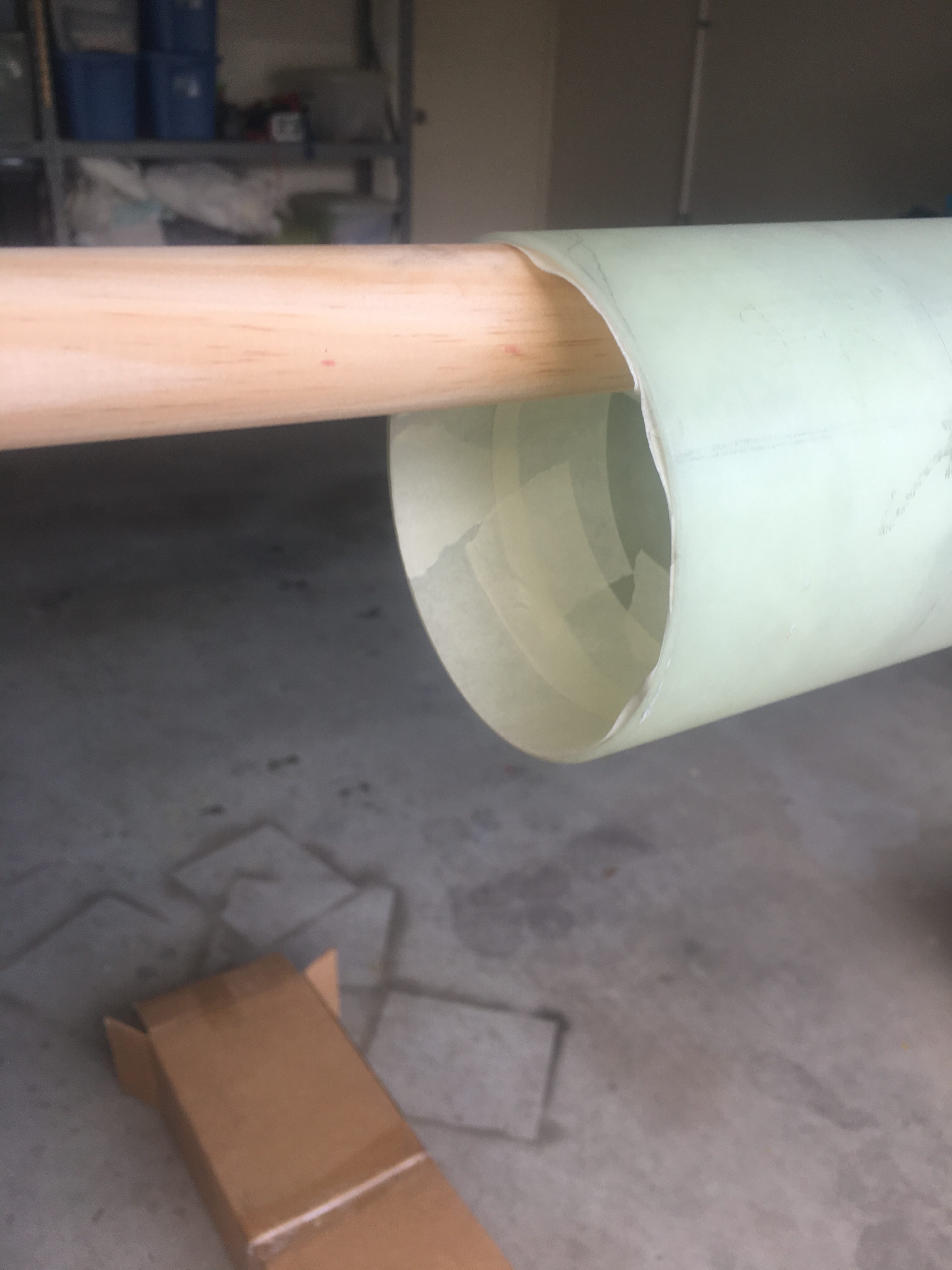
Loading the recovery systems into the Air-frame.

Here are some photos of how I did it.

3rd test: Checking that there is chance of cable cutter migrating further away from the nose cone.
3rd Test: Measuring length of igniter for Black Powder Charge well. Should be about 27cm.
Determining any potential issues with igniters/charge well/shock cord.
3rd Test: Tape igniter cable to shock cord, at two points with painting tape. Just trying to keep things orderly.
3rd Test: Packing parachute bundle into air-frame.


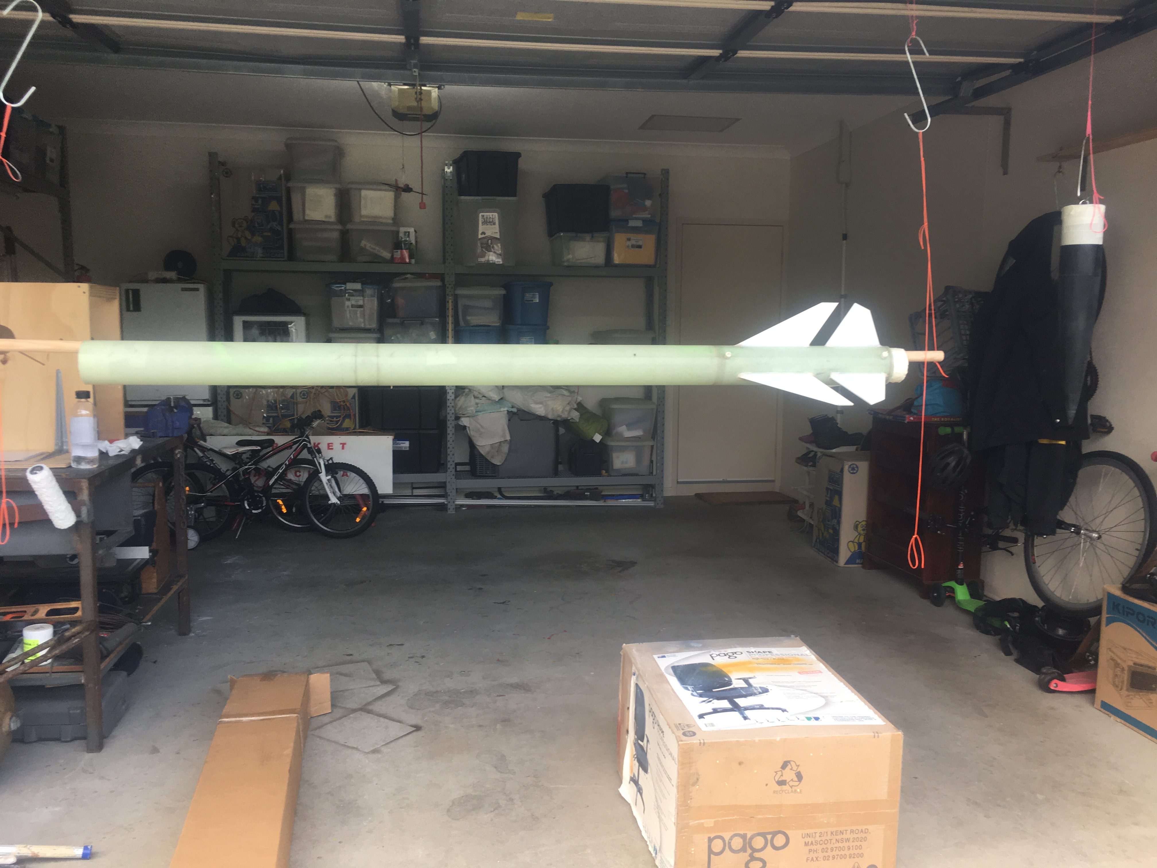
Results of the Ejection Test

After the test we observed:-

  • No tangles. Great!
  • One of the Z-folds opened up, two left to open up (This is good). The reason this is good is because we expect the load to be “fairly” significant when the parachute inflates and these Z-folds will help reduce load on the rocket components.
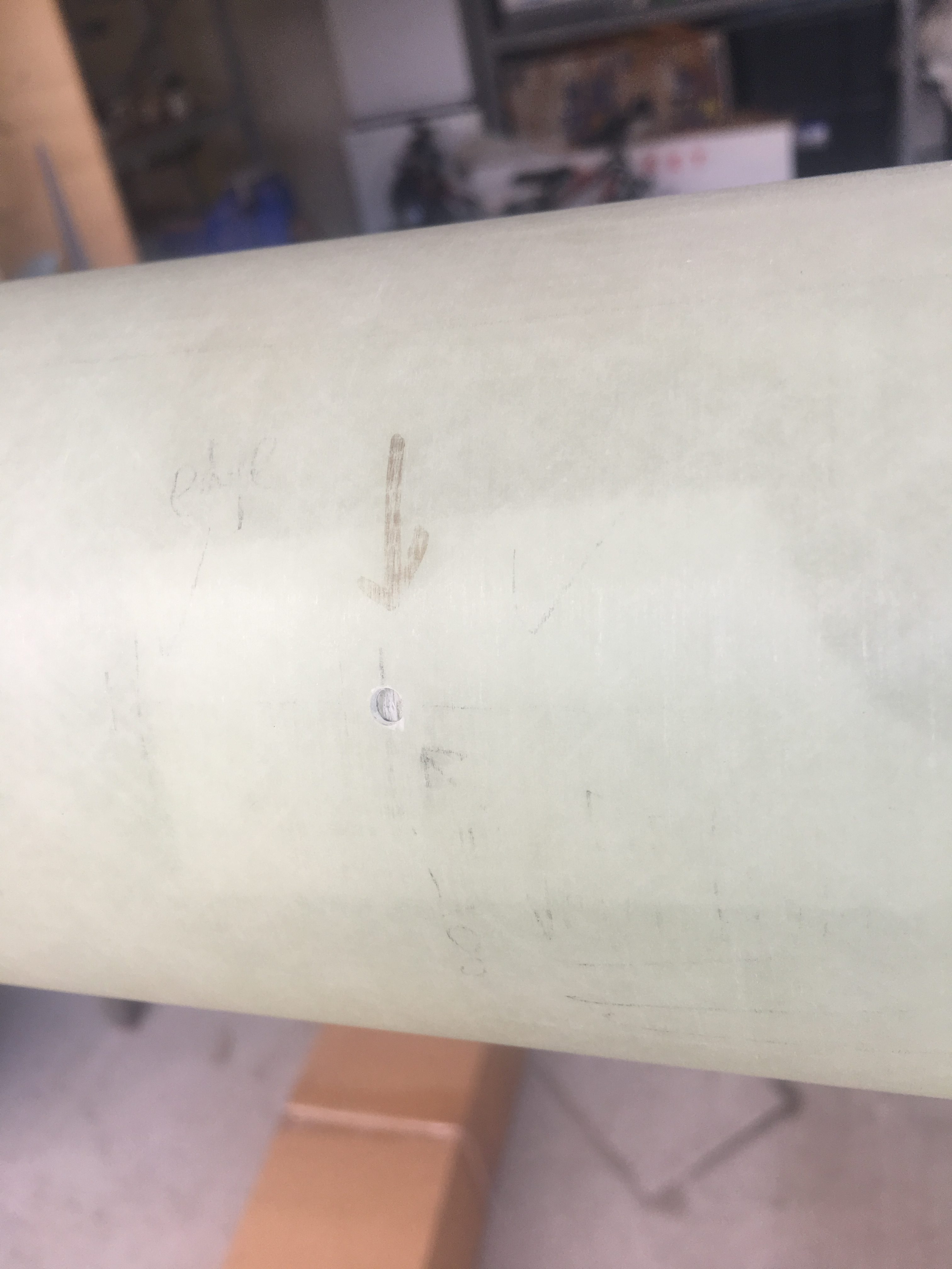
  • There was no damage to any component (though the charge well is showing some wear after three tests. It is still in good enough condition for use in launches.
  • The Cable Cutter still attached to the parachute
  • The e-match wiring in-tact


Here are some photos and a movie.


Showing off parts after ejection - side view. Take note of ruler.
Showing off parts after ejection – side view. Take note of ruler.
Inspection reveals no issues.
Inspection of nose cone end reveals no damage and cable cutter igniter intact. No tangles.
Inspecting Cable Cutter and parachute/Nomex blanket. Seems to be intact.
Inspecting parachute - no damage.
Inspecting parachute – no damage.

Testing the Igniters

What I wanted to test

I am using a Pico AA2 Altimeter and I wanted to run a few tests:-

  1. Test that the Altimeter seems to work – i.e. will detect launch and can detect Burnout and then Apogee. I do this test because I wouldn’t want to fly with a faulty Altimeter
  2. Test that the Altimeter with the 2 x 3.7v 180maH LiPO batteries can supply the current required to fire two e-Matches one after the other
  3. Test the Cable Cutter and the procedure to set it up.

The Set-up

Here are photos taken during the set-up.

Igniter already threaded through cable cutter closure.
Tape put around the igniter, to reduce chance of shorting against the Cable Cutter case.
Hot Glue to keep the black powder in.
All the igniters connected.
Everything connected.


The Results

Here are the results

Detection of Launch Events

Data from "test" launch on bench
Data from “test” launch on bench

We had the Pico AA2 pointed up while it was configured with 2G = 8 which is equal to about 1/4g. Because the G’s are more than 0.25g, the Pico AA2 thinks it has detected launch.

I then turn the Pico so that it is horizontal. As I do this, the G’s pass through zero, which it takes a motor BurnOut. Then it looks at the area under the curve as the rocket “deaccelerates” and when this area is equal to area under curve between Ignition and BurnOut, it then assumes we have lost the velocity we gained; i.e. we are at Apogee. So it fires the Apogee (A) event. Then, because we are below the 800ft, it fires the Main 0.5 seconds later.


Apogee

This will ignite black powder that will separate the top section of the rocket (including the nose cone) from the main air-frame. In this test, we just want to make sure the igniter does it’s job. Ignites.


The Main

Here we test that Main Output fires.

Conclusion

So I ran this test and I’m now fairly comfortable that the Pico AA2 works. I also observed both igniters working, which means the Pico AA2 batteries can be depended upon.

However, the Cable Cutter did not fire. I suspect this is because of two things.

  1. The piston is a dud – it doesn’t have a “cutting edge” like other photos show
  2. A significant portion of the black powder gas went out the back.

Here is a photo of the piston.

This should have a very sharp cutting edge...a concave hole.
This should have a very sharp cutting edge…a concave hole.
The piston seized up in the cable cutter body. This screw-driver shows how far it was stuck in.

Preparation of area for painting

Painting is to commence on the Sunday (3rd Dec 17), but decided to spend a few hours on the Saturday making sure everything was ready and I’m familiar with the operation of the tools.

  1. Making sure the Compressor works satisfactorily
  2. Looking at the operation of the Spray Gun
  3. Making sure the rocket is level and at appropriate height
  4. That we will be able to paint the Nose Cone while the rocket remains hanging

It was a good thing we checked because I noticed that:-

  • The rocket was not at the right level, it was too high and this would result in tired arm.
  • The Nose Cone jig was right on top of the rocket, and this would mean I couldn’t hang it up and paint it at the same time. So I moved it to the right

All these might seem like small points, but they all go to help make it a successful paint job.

Here are some more pictures of the area where I will be painting the rocket.

Tape on inside to reduce amount of paint getting on inside of air-frame.
Backing masking tape so that paint doesn't go onto inside of air-frame.
Backing masking tape so that paint doesn’t go onto inside of air-frame.
Toothpick to reduce amount of paint going into threads.
Rocket suspended from garage door at just the right height. Nose cone is also suspected from eye-bolt to the right.
Just double checking that the level of the rocket seems to be at a comfortable height.


Selection and Purchase of Paints and Equipment

One of the next tasks is to paint the rocket. I’ve decided to use Two-Paks. I purchased some painting supplies from ColorTek in Cairns.

Two-pak paints - includes gas-can sprayer, thinner, primary and hardner.

Two-pak paints – includes gas-can sprayer, Thinner, Primer and hardener.

I’m not sure what colours I want to paint the rocket, so I’ve had to delay the purchase of these.

Painting hardware

I was thinking that I would need to purchase a spray gun and compressor; however my wonderful neighbour has offered to loan me his. Initially thinking that I should use his for priming and purchase my own gun for the base coat and clear, but now thinking we might be able to use his Spray-gun for all coats. His spray-gun is 1.5 mm orifice which means it is sits between the 1.3 mm good for base paints and 1.7 mm which is good for Primers. So his spray gun should be suitable for all coats (primer, base coat and clear).

Massive air compressor!
Hose
Hose
Spray Gun - 1.5mm orifice
Spray Gun – 1.5mm orifice


Having a practice run at painting

I decided to try doing a practice paint run using the Colorpak gas-can sprayer. Below are some photos of the results.


Inspecting paint job - 3 layers of primer on PVC tube.
Inspecting paint job – 3 layers of primer on PVC tube.
Close up view of painted surface before painting.

I will more then likely do a small test run on the day before I start painting the rocket – though I’m not expecting too many issues.

Katana 4 – Material Weights

I’ve weighed all the components of the rocket. I’ve tabulated them below.

To identify which parts I’m referring to, I’ve included a picture of the components on the installation instructions.


front-page-components


Booster Airframe: 1494 grams

Motor Mount: 443 grams

Payload Airframe: 721 grams

Nose Cone: 349 grams

Nose Cone Coupler Tube: 222 grams

One Top Fin: 151 grams

One Bottom Fin: 113 grams

Bridle Strap: ~40 grams

Avionics Bay Fibre-Glass (52mm length): 60 grams

Avionics Bay (Wood + Bulkheads + threaded rod + nuts + washers + eye-ring bolts : 395 grams

Nose Cone Bulk plate + Eye Bolt + Nut: 90 grams

Avionics Bay Coupler (275 mm): 322 grams

Centering Rings (2 of these): 15 grams

We need to know these weights so that we can create a simulation file in Openrocket to simulate the flight of the rocket.


NOTE: I’ve opted to use a different sled arrangement in the Avionics Payload. Wasn’t happy with the one provided. The weights are almost the same, just a few grams lighter.

Pushing the boundaries – Next Flight Objectives

The only way to succeed is to not shy away from setting major goals. In particular, the next launch is going to build significantly on the previous launch. The goals of the next launch are to:-

  • Miniturise the PCB significantly
  • Use smaller ‘solder-on’ LIPO Batteries
  • Design PCBs, so they can be daisy chained. This is so that when we get our ‘five’ PCBs from the PCB manufacturer, we don’t use one and waste four. We would be using 2, or possibly 3 of the PCB in the next flight
  • Make the PCB more configurable/flexible in how they can be used.
  • Resolve issue with Air Pressure sensor
  • Utilise greater memory storage with i2c fRAM
  • Use a Accelerometer/Gyroscope (instead of just a gyroscope)
  • Utilise a system to swivel masses around using servos at 0.25 seconds into flight (after some of the motion has dampened down). We want to do this to measure the effect on the flight of the rocket…and so compare to previous results.

This is certainly a huge leap, but not unobtainable. There are many independent parts…some might succeed, while others might fail. So there is sure to be some success, somewhere.

We would need to use a 3-D Printer to turn this into reality.

We are initially going to do a mock-up using Perspex and some electronics in a breadboard. We will initially concentrate on the Servos and their ability to move quickly and consistently.  If this works okay, then we will go about :-

  • Designing a special case PCB
  • Purchasing a 3-D Printer to create the mechanical device

Below is a screenshot of the design inside Blender.


Servo controlled system with electronics boards pulled to left/right. Servos are green, gears are red.

Preparations for next model rocket launch

A lot of work has been done constructing the payload and programming the micro-controller. Preparations are now underway for the next model rocket launch.

Below is a picture with everything assembled.

Payload assembled into Rocket

The payload airframe section (the grey section in the above picture) will be painted white. Read on to find out more about the payload and what it can do.

Payload

The launch will have an experimental payload included on it which will:-

  • Capture Video of flight at 720 x 480 with sound using a 808 keychain camera
Surveillance Camera
Surveillance Camera
  • Capture and record gyroscope data (rotational speed) using a L3G4200D breakout board
Gyroscope sensor
Gyroscope sensor
  • Capture and record air pressure and temperature measurements using a MPL3115A2 sensor
i2c based MEMS  Air Pressure sensor
i2c based MEMS Air Pressure sensor


The final payload (before sliding into air-frame) looks like:-

Front view of payload tray

The sensors are sandwiched between the PCBs and the battery board. Space really is a premium.

Back view of payload

Notice the coin cell batter and the rotary switch on the LHS and the camera on the RHS. The rotary switch is accessible from the outside.

Payload Data

It is certainly an ambitious project, but hopefully will produce some results that will allow us to characterize the motion of the rocket as well as test our payload design and operation. The Air Pressure results will allow us to approximate the altitude of the model rocket over the flight which we will then be able to compare to our simulations. The gyroscope readings will be very interesting when we compare with video recorded motion of the rocket. Temperature will be interesting, but is of less importance.

I’ve created a video that allows us to compare the ‘real world motion’ of the payload when compared with the motion depicted using the gyroscope data. See below.


The Rocket Motor

We will be utilising a G76-10G Aerotech engine. This translates to an average thrust of 76 Newtons over the total burn time of approximately  Below is a plot from OpenRocket.


Simulation of launch

As you can see, this rocket will achieve an altitude just shy of 300 metres. (less then 1000 feet). This is well short of the 4000 feet ceiling we have at our launch site. We still expect the launch to be spectacular.

Remaining Preparations

Remaining preparations include:-

  • Generating Launch simulation to ascertain key information like ejection delay, speed of rocket off the launch rail
  • Confirming CG and CP points (checking stability of the rocket)
  • Confirming launch location suitability and timing
  • Checking and testing launch Electronics systems
  • Charging batteries
  • Performing inventory check and packing boxes with required items
  • Writing and testing procedures
  • Double checking motor risks (issues that other people have recognised with the motor). The AusRocketry forums were helpful in this respect.


A Roadmap

As I have indicated, this is a massive undertaking and this is to be broken down into several smaller projects.  Below is a rough idea of how I think this should be done. Within each ‘project’ there are some main technical objectives and properties of each flight.

Obtain Amatuer Rocket Certification L1

  • Solid Composite Motor
  • Parachute Recovery
  • Launch Platform
  • Launch Electroncs
  • Multiple flights likely

Obtain Amatuer Rocket Certification L2

  • Solid Composite Motor
  • Parachute Recovery
  • Spin stabilisation
  • Basic electronics (Tracking + Camera + Sensors)
  • Multiple flights likely

Obtain Amatuer Rocket Certification L3

  • Purchased Hybrid Rocket Engine
  • Drogue Parachute + Parachute Recovery
  • New Launch Platform
  • More advanced electronics (Tracking + Camera + Sensors + acutators for Parachutes)
  • Multiple flights likely

Design/Build Nitrous Hybrid Rocket

  • Perform test burns and characterise the engine over different initial conditions (So we can accurate simulate it).
  • Construct Rocket for new Rocket Engine
  • Drogue Parachute + Parachute Recovery
  • New Launch Platform
  • Perform multiple Test Flights

Rackoon

  • Build Launch platform
  • Build electronics
  • Build Hybrid Rocket
  • Design/build/organise Balloon systems
  • Perform test Flights (controlled, small ones)
  • Perform Flight
  • Ultimately perform Rackoon Flights

NOTE: I suspect this last part project will be a lot longer to complete than the other ones.

I expect things to change as take this journey. However, I believe that is a sensible good start.

Obviously timeframes is one area that I need to think about. This series of projects looks huge, and indeed it is. But I believe that with some careful planning, we can re-use components and techniques used from prior projects. Not only will this save time, but it will give me an oppotunity to fully test components and improve upon them over time.