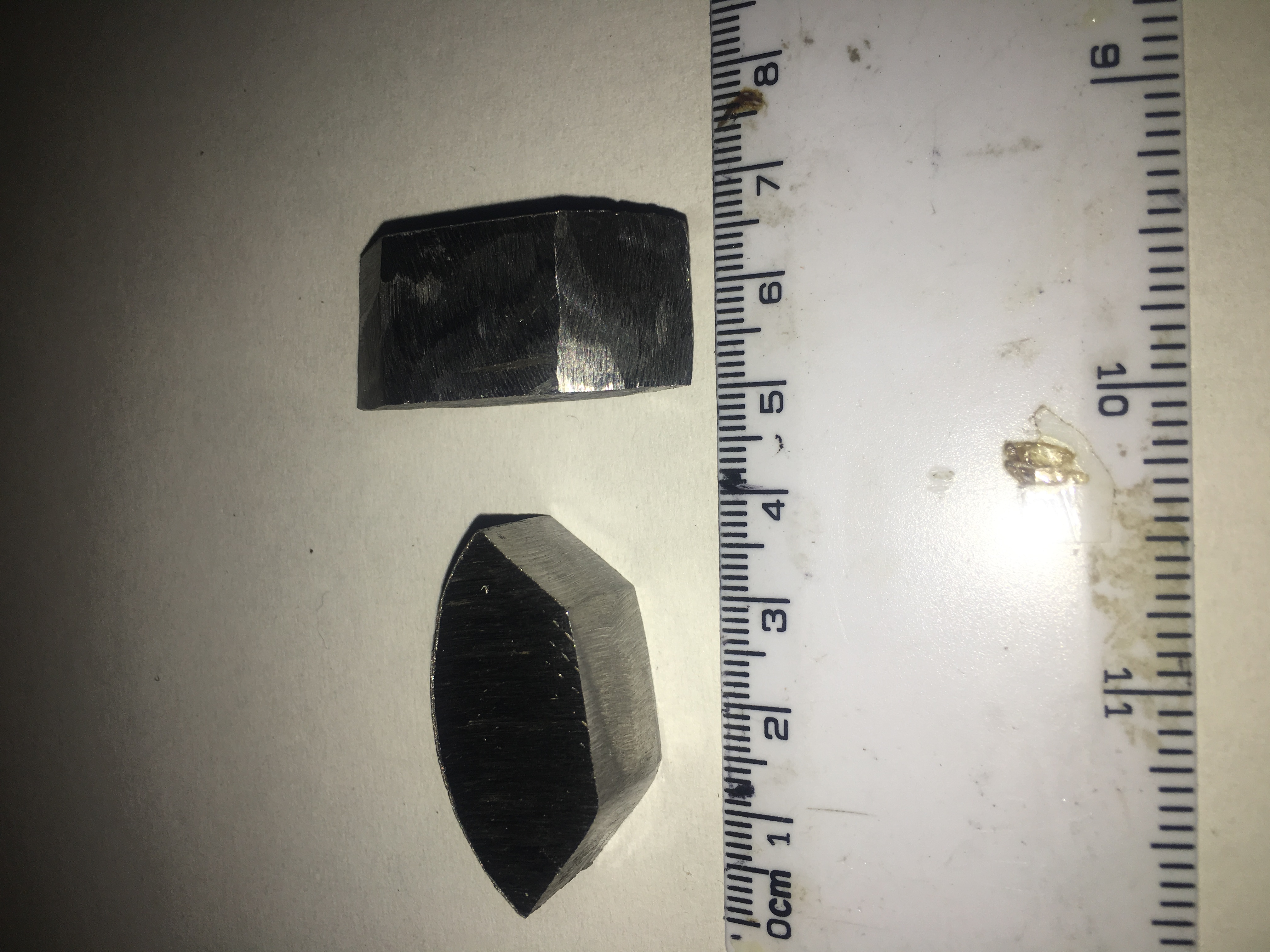
I’ve started construction of the weights that will be swung around by the Servos. They each have the following properties
Built from Steel Rod with diameter 50 mm
Thickness of 15 mm
Angular distance is 90 degrees
10 mm cut out from centre
Weight is approximately 46 grams each
A picture of these is shown below.
Weights for Stabilisation System
By having these weights positioned so that their curved edge is 26 mm from the centre of the rocket, we should be able to move the Centre of Gravity by 1.25mm. This will be a significant achievement if we can complete this payload. This will mean with a 100N thrust motor, we will get a moment of 0.125Nm. If the rocket has a Moment of Inertia of 0.25 kgm^2, then we are looking at Angular acceleration of 0.5 rads-2. This means that for a burn of 1.5 seconds in a vacuum, this would result in:-
Angle of Rotation = 0.5625 radians = 32 degrees
Rotation speed = 0.75 radians per second = 43 degrees per second
During tests on ground (in atmosphere), we would experience aerodynamic forces that would help to counteract this movement, so the effects would not be so great.
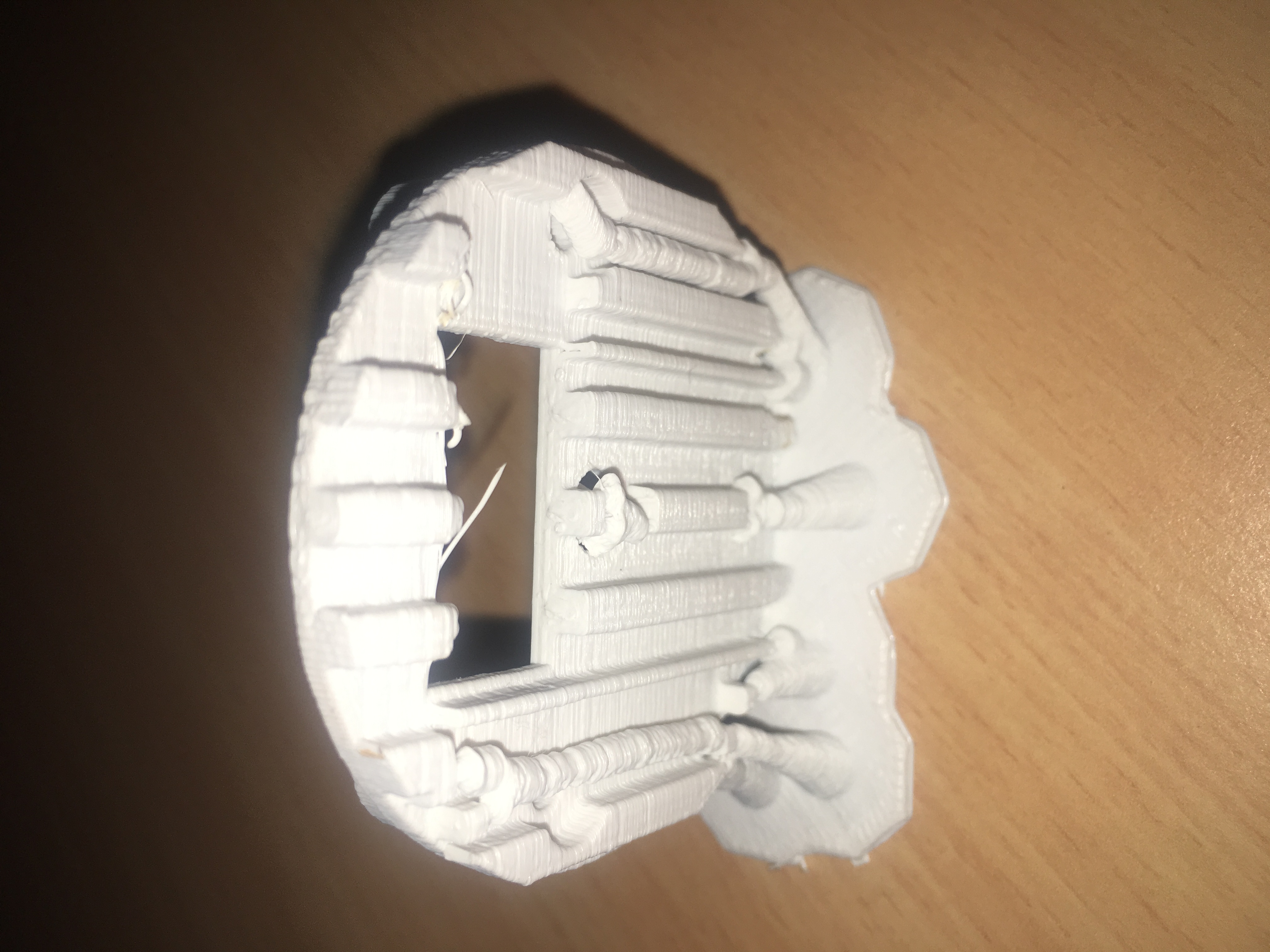
I’ve taken delivery of the sample prints that I designed using FreeCad. Fortunately the people who did them (Bilby3D) did two prints for me. One was printed on the side, one was on its circular base. One was done on the side because of the scaffold material in the horizontal print is a nightmare to remove. My first lesson in 3D printing!
Some pictures of what was produced below:-
Printed on side (Front view).Printed on side (Bottom view).Printed on base (Top view).
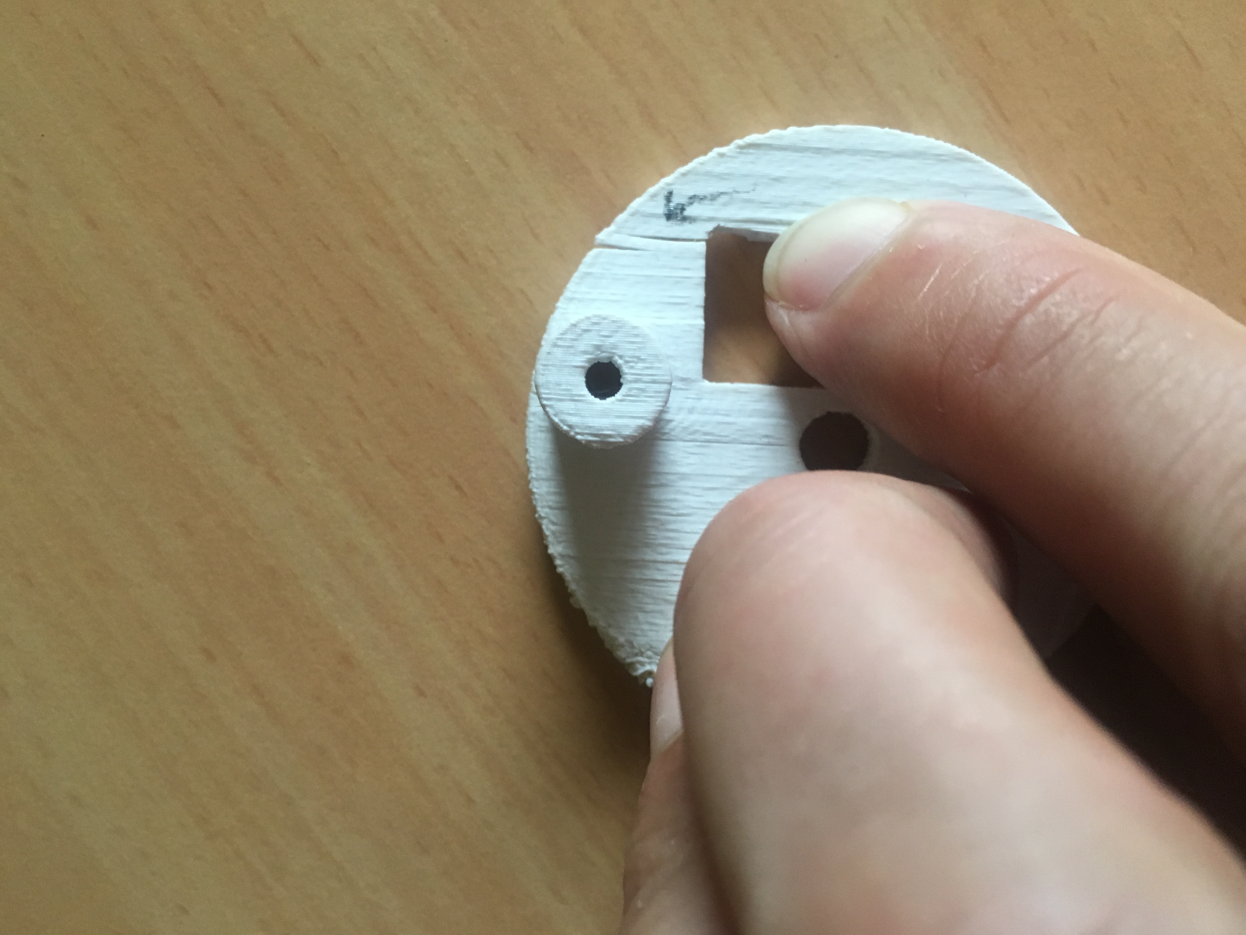
We started to remove some of the material to try and insert the servo. I mis-judged the amount of material that had to be moved to allow it to fit. I didn’t remove enough material and the 3D print cracked near the narrow edge.
Notice the crack in the pirint (where the arrow is pointing)
Of course the underlying issue here is that I did not take into account the shrinkage that occurs when a ABS printed object cools. ABS shrinkage is approximately 8%. (Shrinkage for PLA is about 2%).
So what I’ll be doing next is designing it with slightly large dimensions. What I’ll probably be doing is initially do a disc that is 8% bigger and make sure it fits inside the Air-Frame. Then I’ll use this contraction percentage to work out what I must multiply other dimensions by to get the correct dimension (after shrinkage).
I am also serious considering using PLA. Much more work to do.
In this post we focus our discussion on the device used to adjust the Centre of Mass. This device consists of two masses that we rotate independently to produce a resultant change in Centre of Mass. We split the masses in two to:-
Halve torques required to rotate them (if they were combined)
Allow us to obtain neutral position (by having masses opposite each other)
Allow movement of Centre of Mass around…by moving masses
Reduce movement of Centre of Mass by moving masses apart
This isn’t a new idea. We solved this problem with stepper motors. Unfortunately the stepper motors have problems. The are:-
Too heavy
Have insufficient torque
No means of verifying the position
Large current requirements
Require specialized electronics – Driver board
So I put some thought into how we could make this lighter and have greater torque. The only solution I have been able to come up with is a geared system using high torque servos.
The trade-off is that we can’t continuously rotate around. But this shouldn’t be necessary because we only need this system to operate for the first 1 to 2 seconds of flight. We do not expect the rocket to rotate about it’s Y-Axis significantly. Put another way, we don’t expect erratic motion, instead some clear rotation in one plane that requires some correction. There may be some rotation as the rocket builds up speed and the fins (with their imprecise alignment) results in some rotation about y-axis.
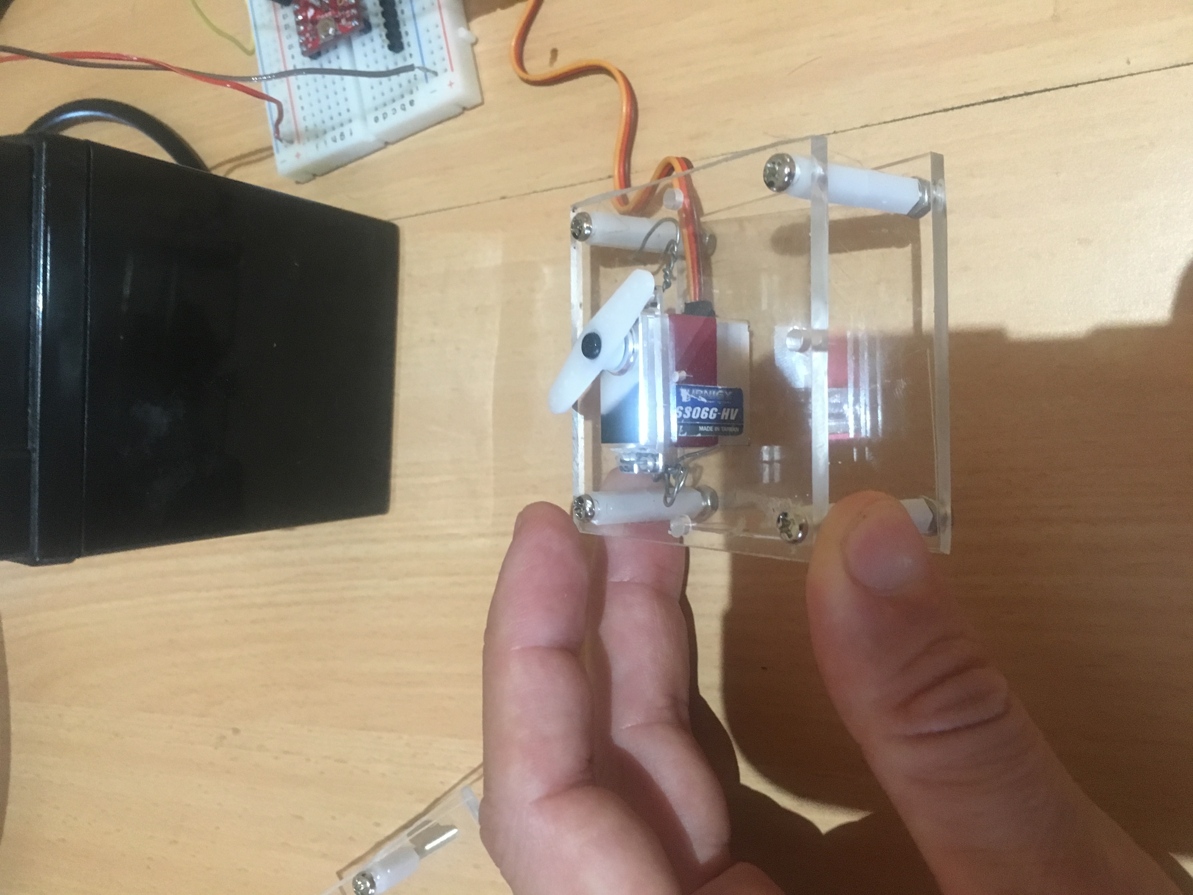
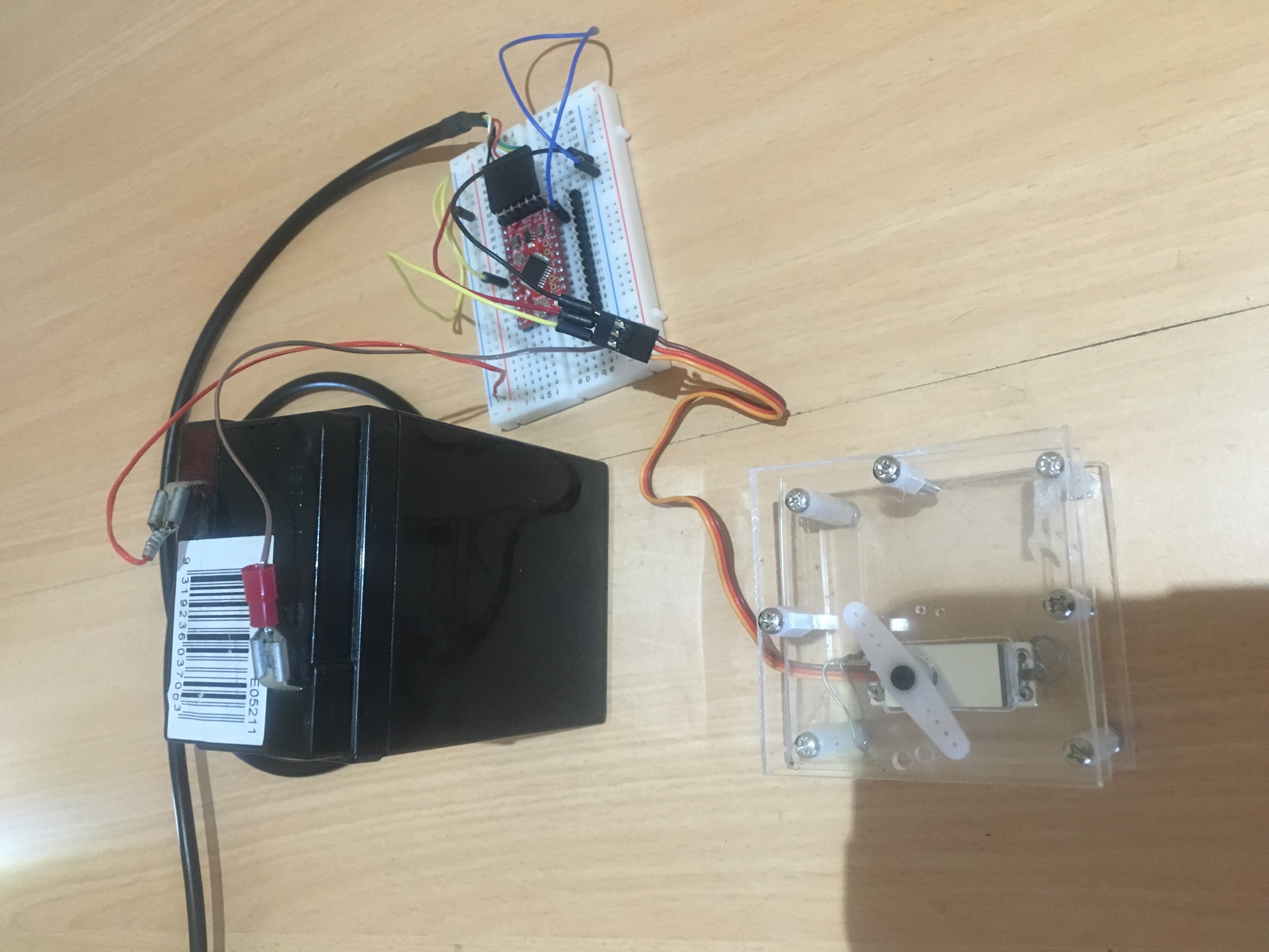
We have started work on a “pre” prototype system using Perspex. Below are a few pictures of system connected to Arduino.
Set-up without top perspex topPerspex framework with Servo, attached to Arduino controller
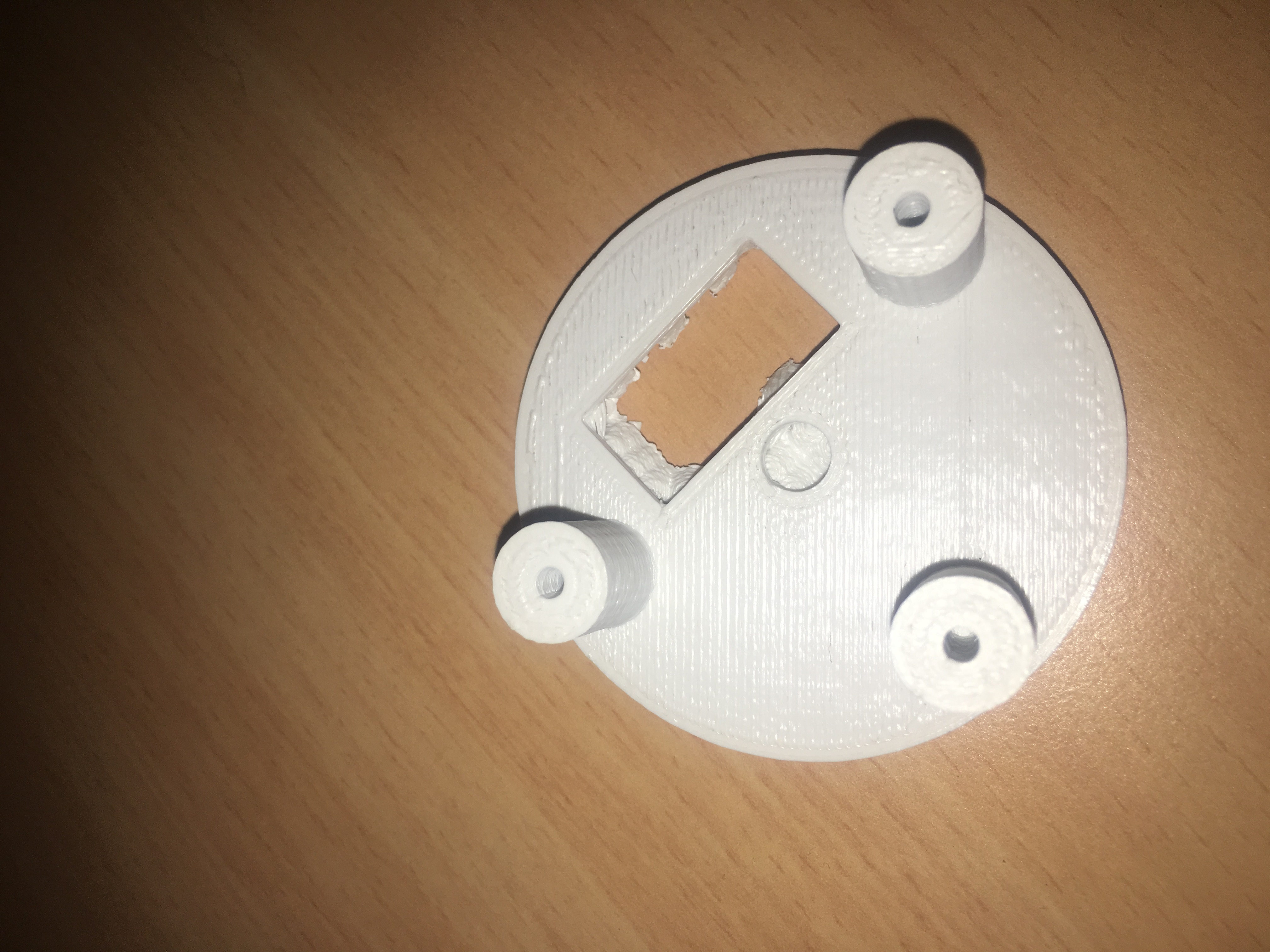
We ultimately aim to have 3-D printed components to form the framework. Below is a preliminary design for the bottom section that the servo is joined to.
[stl file=”framework_v0.02.stl” ]
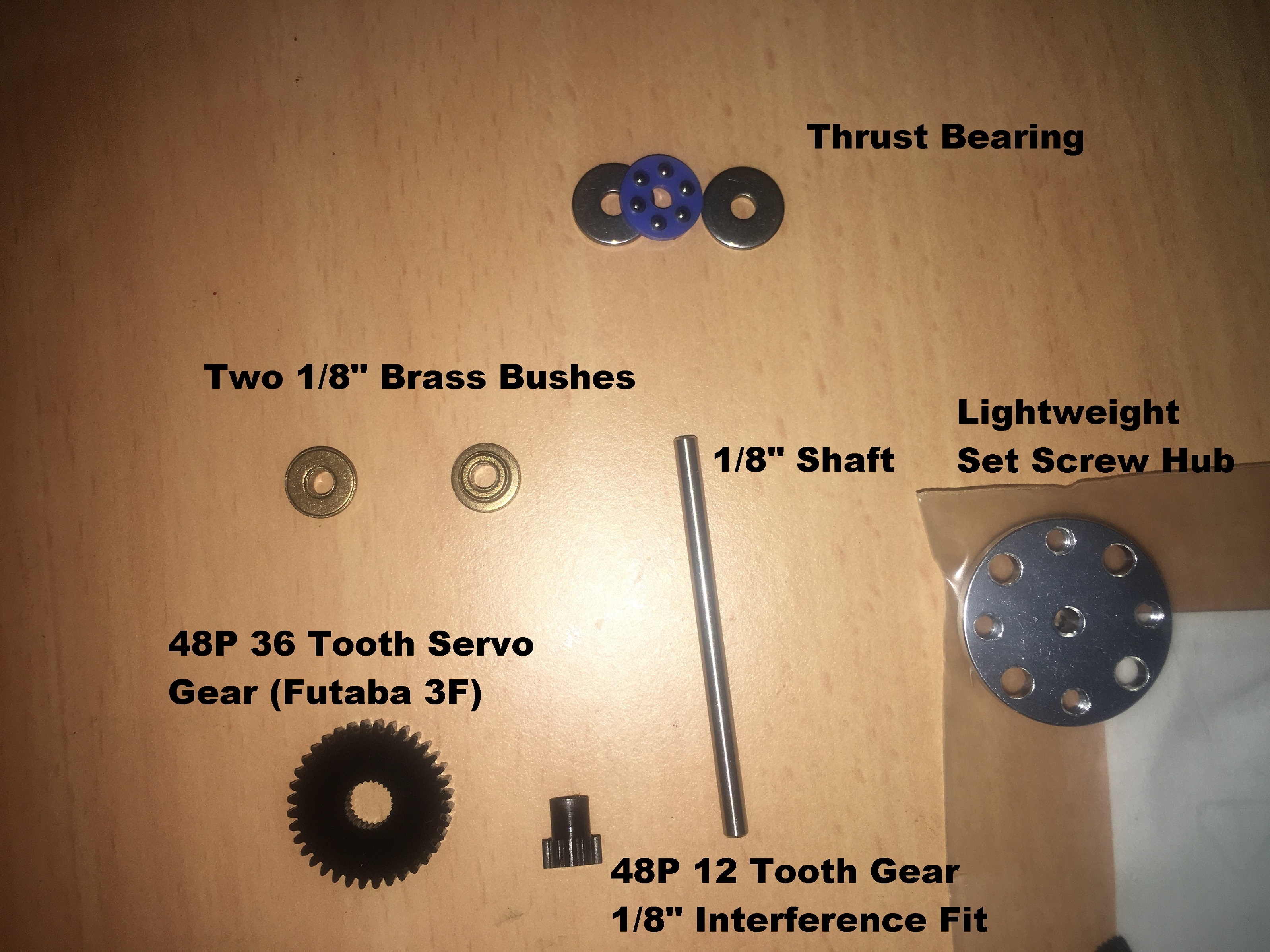
We have ordered components from ServoCity. This looks like a very good supplier of quality components; certainly comprehensive. Below is a picture of the parts we have recently purchased.
All parts from ServoCity Used to construct mechanism
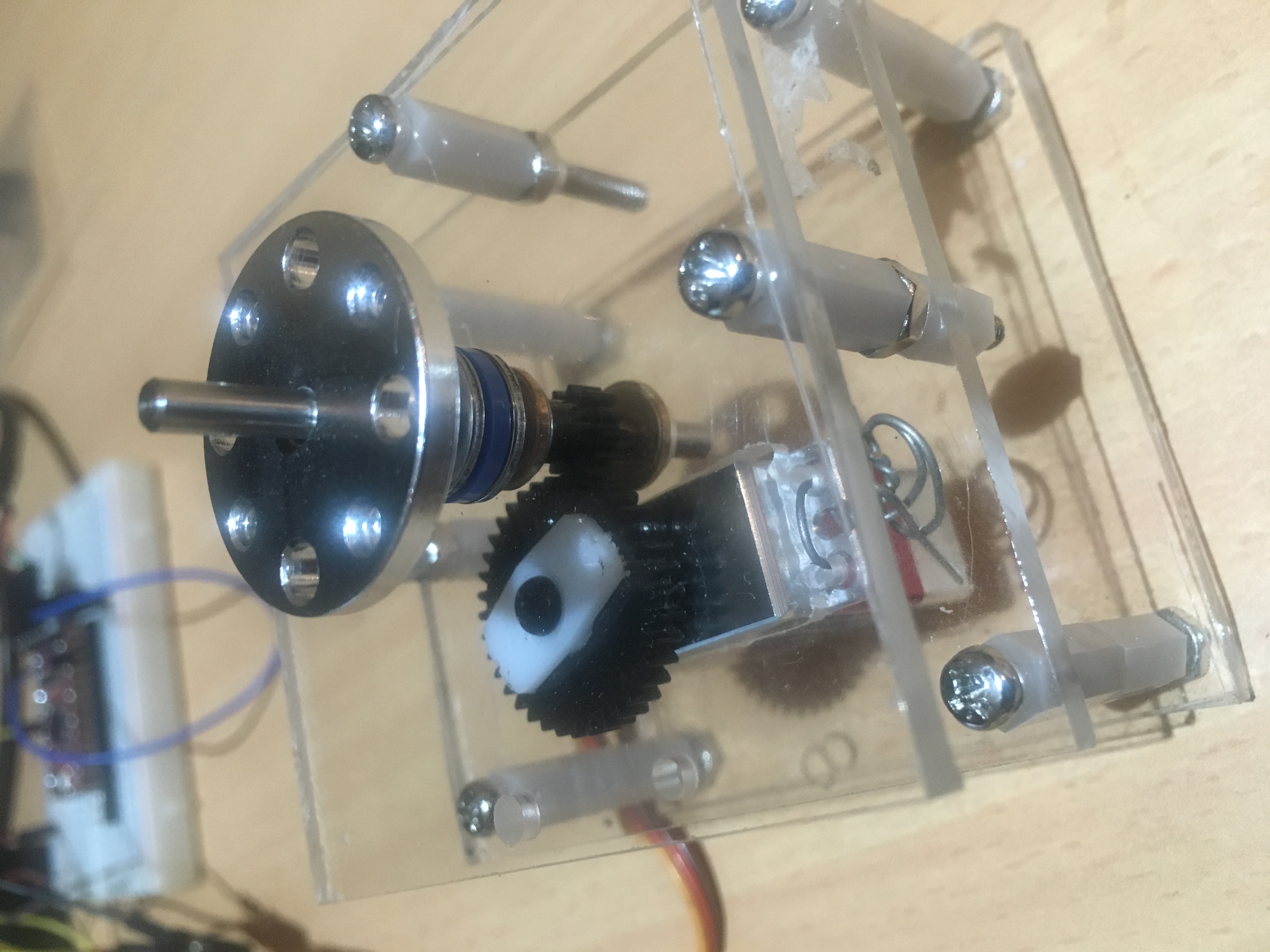
We had problems with the 48P 36 tooth gear. It was larger then the Spline on our Servo. So, I drilled out the servo gear carefully and then press-fit a Servo attachment into the gear (which I’ll later glue). Then I carefully drilled holes in the Perspex and press-fit the bushes. The final mechanism looks like:-
All components assembled.
The gear ratio is 3:1.
This means:-
Travel distance is now 3 x 135 = 405 degrees
Travel speed is now 60 degrees in approximately 0.017 seconds
Torque is reduced from 3.7kgf.cm to 1.23kgF.cm
We will ultimately look at adjusting the gearing,by inclusion of another 12 tooth and 24 tooth gear to give us a gear ratio of 6:1. Initial design work suggests that this should be doable. But for the purposes of the next flight test, we do not need to work on such a system. This system should be adequate for characterizing the effect of small movements of the Centre of Mass.