Category Archives: Technical

The big day!

I wrote a single page e-mail to family on the days proceedings. I decided I would share this here on the blog.

The days proceedings

Jeremy, Grandma Patsy and I got up at some crazy time 04:30 for Grandma Patsy and 05:00 for Jeremy and myself.
We had a quick bit of breakfeast -⁠ weetbix…teas and other foods.

Then I loaded all the boxes (which I had left near the front door) into the roomy Toyota Kluger… and then we set off.
We all spotted some Hot air balloons as we started our ~60min journey to Cedar Grove Road. Most of the trip was in lovely rural surroundings.
About 1/2 way into the trip we all stopped off at a small cafe in Canungra called the “Outpost Cafe”.
There Grandma Patsy got a coffee – flat white – hot in a take-away cup, and I got two slices of toast with Vegemite…sharing the facilities
with middle-⁠aged(and older) “friendly” bikies.

Then after the usual pit stop activities, we resumed our drive.

Eventually we got to Jimboomba…I was a little anxious because the road seemed to go on forever and was wondering if I’d missed some vital turn-off.
I had nothing to worry about. About 10 min later, we spied the launch site. The first thing I could see were blue portaloos. I was delighted to see them.
2 mins later we were driving into a paddock. Grandma Patsy did the honors opening the gate and then we were back together. Thanks Grandma Patsy 🙂

We met up with about 4 other chaps who kindly suggested we not park so close to the toilets. We took their advice and parked further away.

There was no equipment at this stage…and it became apparent that the arrival of the equipment was lagging. Eventually a huge truck made its way and before we knew it, Jeremy and myself were helping set up all the equipment. We stuck mostly to erecting several Gazebos. Jeremy was terrific getting the pegs and hammering them in.

We got our equipment on to a table…one nice chap said…possession is nine / tenths of the law….

Then someone stole the two tables from under us!!

Fortunately, someone loaned a table and the Tarp I brought all the way from Cairns, suddenly became valuable property!

8:30 came and the launches started. Dave, Lake, Reef and Vanessa’s father arrived…and eagerly watched. At various occasions I helped them set-up their rockets. Jeremy gave up waiting for me to get him a motor….I suggested he approach Blake with some money and ask him for some advice on what motor he required. Blake helped Jeremy with the motor purchase and I helped Jeremy assemble the motor. Jeremy’s flight went really well.

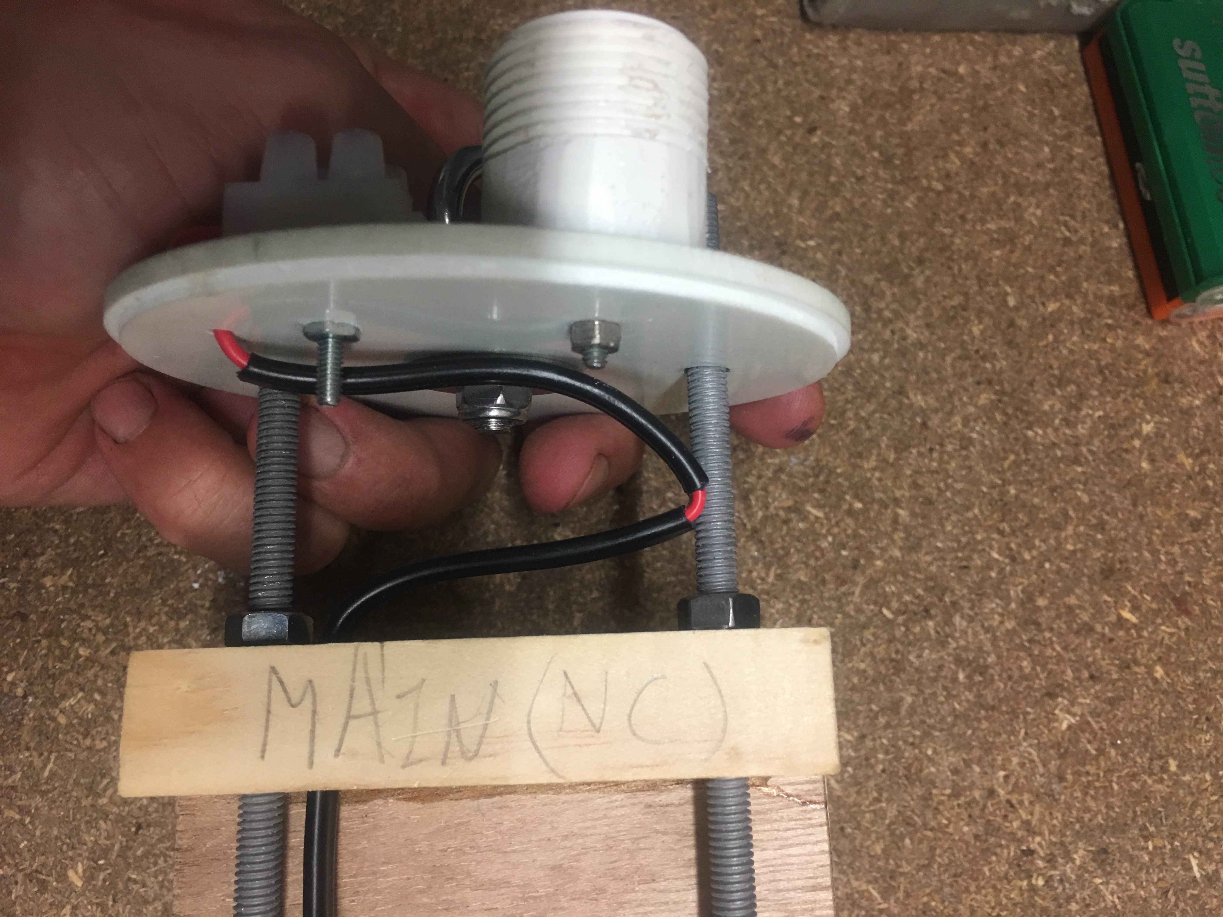
For about 4 hours I set-up the rocket. Everyone was looking in…Jeremy was taking photos. Grandma Patsy helped as much as possible, making sure no one got too close. I was a little nervous having this awesomely powerful motor on the table and people casually walking past it. But we were following procedures to a tee.
I had my instruction manual with check-boxes and pictures…and only after inspecting all components, did I actually start assembling components. So many things were checked and re-checked.

Then at about 12:30….the launch pad that I wanted to use was vacated…their rocket went up…and then splashed down into the Logan river….(only about 4 hrs later did some university students practice their swimming skills to pull that rocket…a 4 metre beast…from the river. Lucky they don’t have crocodiles down this way!!).

I didn’t take any photos myself… I wanted to see it through my own eyes and be in the moment…so to speak.

Recovery

After the flight, Jeremy, Lake and myself bounded up the paddock, through long grass to recover it. 30 min later, we were talking back….Lake was holding the Nose cone, Jeremy was holding the large Parachute and I holding the rest of the “bits” as best as I could….across the muddy river bed in my best Black shoes (well almost the best…the ones I wear to Darwin for work).

Hot, tired, sweaty and alive. 2 litres of fluids later…felt a bit more alive…Sweet feeling of success.

It was not quite over though….

Videos

I do have a few small videos of the launch.

https://youtu.be/o3FykRAwLEA

https://youtu.be/SZSu98DQ_H8

Here is a larger video – with more details on the whole build/launch.

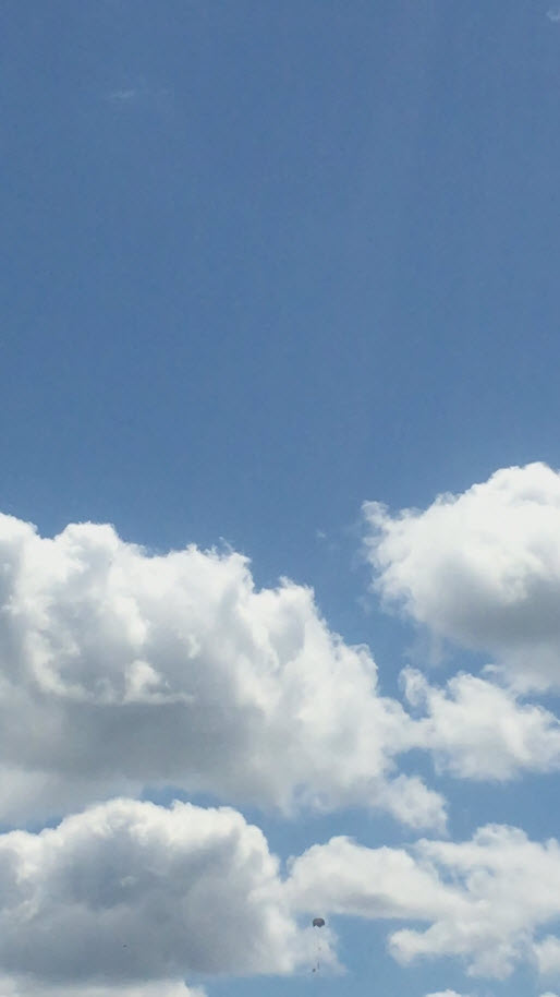
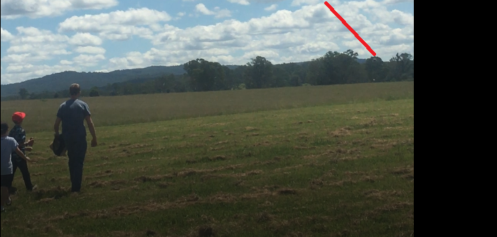
Alas I do not have photos or videos of it coming down…. But I assure you….it was seamless.

Here are the best screenshots I got of it coming down.

Coming down...top part of it.
Coming down…top part of it.
Almost hit the ground.

Flight Data

graph

summary2

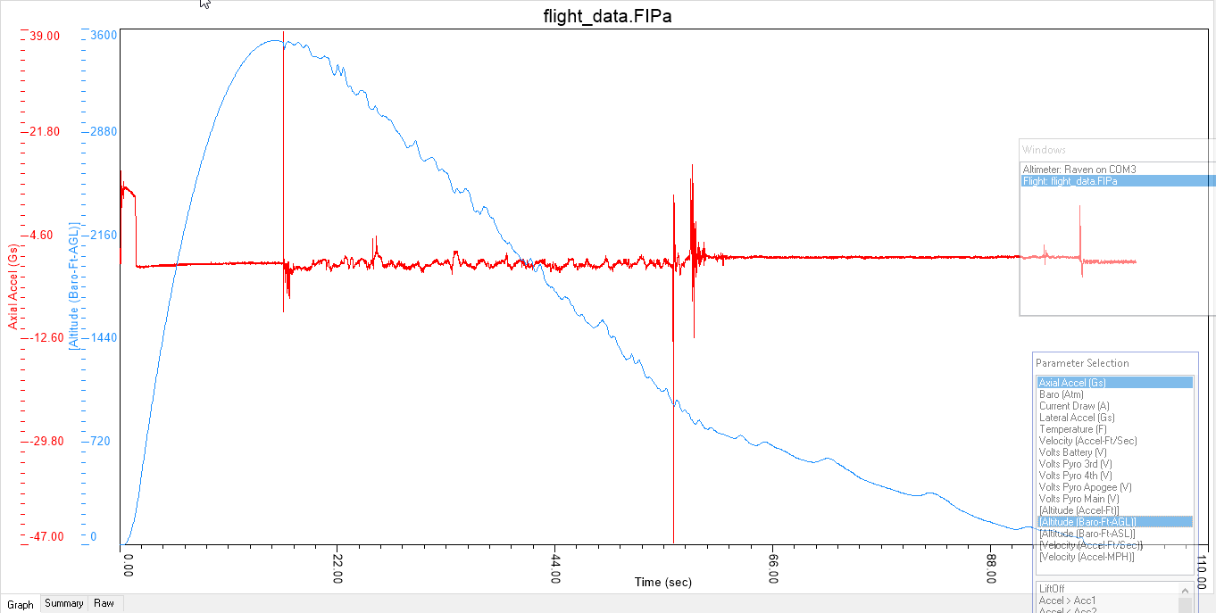
As you can see, it reached an altitude of 3528 feet. Very impressive.

Parachute Sizing + Shock Cord

Drogue Parachute

Very particular about having a Drogue parachute used at the top of the flight. They are supposed to be built to survive extra forces. The choice of Drogue parachute is important because when the main parachute is ejected, I don’t want the rocket travelling too quickly. Some websites have said 50 to 60 mph (which translates to 22.3 ms-1 to 26.8ms-1. Open Rocket raises alerts when I hit about 22ms-1. I’d prefer to keep it within range that doesn’t produce warnings inside Open Rocket. This meant a Drogue at very minimum = 28″. Probably can’t get a 28″, so would be a 30″ Drogue.

Cert-3 Drogue Chute

I have since this found a parachute called SkyAngle CERT-3 Drogue. The main website is:-

http://www.b2rocketry.com/Cert-3.htm

The Drogue Parachute has a Cd of 1.16, but this is based on just the area of the ‘cap’, not the whole parachute. (This is not how parachutes are normally done; people usually use the whole canopy area. The website has a link to a calculator to get decent speeds:-

https://descentratecalculator.onlinetesting.net/

I put in weight of rocket as 8 kg – this is for my L2 flight. I selected the 24″ Cert-3 Drogue. Results are:-

Descent rate:

  • 70.26 ft/sec
  • 21.41 meters/sec
  • 77.09 km/hr
  • 47.9 mph

This is good. It indicates that the speed is less than 50 miles per hour.

For larger 75mm motor, L1395-BS-0, we are looking at a total weight of approximately 10.7kg. When I put these numbers into the decentrateCalculator, I get:-

Descent rate:

  • 81.26 ft/sec
  • 24.76 meters/sec
  • 89.16 km/hr
  • 55.4 mph

So this might be okay too.

How does this fair with calculations?

I would like to see if I can get similar results using well known equations.

Velocity = SQRT(8 * m * g/(pi * p * Cd * D * D))

m = 8

g = 9.81

pi = 3.1415

p = 1.22 kg/m^3

Cd = 1.16

D = 0.61cm (24″)

Putting this all in, we get:-

V = 19.5ms-1.

This does not agree with above calculated values. It is slightly under.

What are the Risks with a 24″ Drogue Chute?

The main concern is that the speed of the rocket is such that as the main parachute is ejected, it shreds it, or it damages the rocket in another way, e.g. rips out the shock-cord.

It is probably helpful to also list what we consider to not be a risk

  • Shredding of the Drogue

We can probably do a small calculation to determine the approximate forces that the rocket will experience due to the deployment of the main parachute.

F = ma

m = 8kg

a = Delta V/ Delta T

Delta V = 6 – 22 = -16ms-1

Delta T = 0.25 seconds (BIG GUESS)

We assume the acceleration is constant

a = -16 / 0.25 = 72 ms-1

F = 8 * 64 = 516 N

64kg force = 141 lb

According to :-

https://publicmissiles.com/PMLRecoveryComponentsFAQ.pdf

The shround lines for parachutes > 48″ can take 300lbs of force.

60″ Chutes are even stronger, though there is no figures quoted.

With this in mind, even if a chute opens in 0.25 second, we are looking at a force that is probably survivable.

Main Parachute

Lots of websites suggests a landing speed of about 5 ms-1. I’m probably not going to get that, but I’m thinking I’ll get close using a 84″ PML parachute. 84″ is ~215 cm diameter. Open Rocket simulations produce a landing speed of ~5.9ms-1. I’m going to have to accept this.

Eventually I decided to go for a Cert-3 SkyAngle Large parachute. This was something Blake from AusRocketry was suggesting. I was very glad in the end to get a Cert-3 SkyAngle parachute because it is 61″ across, compared to the 84″ across….this means it is easier to pack into the airframe payload compartment. I believe me, space is a premium in that compartment.

How does this fair with calculations?

I would like to see if I can get similar results using well known equations.

Velocity = SQRT(8 * m * g/(pi * p * Cd * D * D))

m = 7.8

g = 9.81

pi = 3.1415

p = 1.22 kg/m^3

Cd = 1.26   (From the B2rocketry website)

D = 1.55m (61″)

Putting this all in, we get:-

7.3ms-1

This seems high, but if I use:-

https://descentratecalculator.onlinetesting.net/

Mass: 7.8kg

Parachute: SkyAngle Cert-3 Large

I get:-

  • 17.53 ft/sec
  • 5.34 meters/sec
  • 19.23 km/hr
  • 11.95 mph

I trust the decent calculations more than my own calculations. I suspect my D dimensions were incorrect.

Will the Cert-3 Large parachute survive or will it shred?

Now I’m obviously concerned that the 22ms-1 speed of the rocket might be too much for the main parachute. Above 20ms-1, Open Rocket shows warnings. I can see other people in posts, e.g.

http://www.rocketryforum.com/showthread.php?28347-Maximum-Parachute-Deployment-Speed

say that they have done drogueless at 24ms-1 suggesting that upper limit is 30ms-1.

Other Concern

If the Main parachute takes 5 seconds to deploy (and this is all quite possible), then at a speed of 22ms-1, the rocket will have potentially travelled 110metres (360 feet). So if I set the rocket to deploy at ~700 feet, will still have another ~110 meters to go. I think this is satisfactory.

I am contemplating changing the deploy to 1000feet. It will give it a bit more time to open.

Shock Cord

Many people suggest Tubular Nylon. It is extremely strong. AusRocketry says 9/16 version of this machines has a max tensile strength of 2000lb (that is lb, not lbf). Another site with same size material has a strength of 1500 lb. So not sure why there is a discrepancy, but perhaps I should question the AusRocketry value.

Now, let’s consider the situation where we have some Black Powder ignite and produce a pressurized chamber. Energy is neither destroyed or created, so we need to account for it. Energy would go into:-

  • Breaking the shear pins
  • Heating/moving air as its bursts the components apart
  • Imparting energy into nose cone
  • Imparting energy into the Avionics Payload

We would expect the Nose Cone and Avonics may to be sent in opposite directions (conversation of momentum) and the Shock-cord to be stretched to its maximum length and then it would produce an equal and opposite force, that keeps the components tethered. This Shockcord is effectively like a spring – and like a spring it stretches and absorbs energy. We can work out what forces are in the ShockCord based on the energy it absorbs.

F = \sqrt {2kE}.

k = Spring Constant

E = total energy

F = force that the Shock-Cord is experiencing.

If the force (F) is excessively large (exceeds the rated strength of the Shock-Cord), then we have  a problem.

So how much Energy is being absorbed?

The Black Powder produces a pressure and we know the volume of the tube. We assume that the Blackpowder ignites completely and the production of all these gases occur before any venting can occur. All ideal (and unlikely in the real world) but this gives us a conservative look at it.

Now, E = PV = nRT

P = 10psi = 10/14.7* 101325 ~ 69,000 Pa

V = 0.049 * 0.049 * 3.1415 * 0.41 = 0.0031m^3

E = 69,000 x 0.0031 = 213 Joules

This is a fair amount of energy.

If k = 30,000 (and this is a BIG GUESS)

F = sqrt (2 * 30,000 * 213) ~ 3600 N = 367 kg = 807 pounds

This is well short of 1500 lb or 2000 lb (AusRocketry).

Of course this all hinges on choice of k and I’m not sure if this is a good value.


A Second Paint Job

In the first paint session I managed to paint the nose coat with base coat and clear coat. I base coated the booster, but had some issues and ran out of blue base paint.

The second paint job is to complete the painting tasks. For the second paint session I decided to purchase a gravity-fed spray gun.

$30 dollar spray gun - Gravity fed. Well worth the investment.
$30 dollar spray gun – Gravity fed. Well worth the investment.

For the second paint session I purchased new :-

  • 1 litre of blue paint
  • 0.5 litres of thinner
  • 0.5 litres of hardener (activator)
Second batch of paint products for painting booster using new Gravity Fed spray gun.

Unfortunately I didn’t take too many pictures during the second paint session. I was too busy concentrating on the job. The base coat (blue) went fairly well. I have a photo of the booster hung up below.

Photo during painting. Using the gravity fed spray gun.

The big differences this time was :-

  • The use of gravity fed spray gun with regulator. This meant I could actually get the air coming out at the right pressure. With the previous gun, I had no really control over the pressure (well I had no knowledge of what it was set to).
  • More base coat to experiment with
  • Lowered the whole rocket about 15cm to make it easier to paint. Arm won’t get as sore.
  • Had special tray for cleaning gun between base and clear coat
  • Purchased 4 litres of thinner specifically for cleaning the gun. So now I don’t have to use the precious thinner that is supposed to be used for the paints.
Rather than waste valuable thinners used in painting, decided to purchase some, just for cleaning.

Problems experienced during painting

Unfortunately I did get a few runs with the clear coat and I’m very sure it is because I went over the fin-cam too many times. i.e. three passes, when two passes would have been sufficient. The spray was open wide and there was more overlap than I expected. This is due to my inexperience.

I decided not to sand back down to base and do it all again. I decided to just remove the obvious runs and polish the rocket.

Removing the Runs

I removed the large runs by applying some polyster filler compound. After 20 mins it was set and I sanded it down using grit 400 sand paper. This meant I was only sanding the runs and not the area around them. It worked very well. Then I sanded it down with 1200, 1500 and then 2000 to removal all remaining traces of the runs. There is still some undulation of the clear coat because of the flow of the clearcoat, but it is only slightly undulating and is very smooth.

Reflecting on the results

So while I didn’t get the best result, I did learn a lot on what went wrong and how to remedy some of the issues I created. I have to remind myself this is my second paint job in my life. It went reasonably well considering!

Testing out the Ejection charges

I purchased the following eMatches to test out the ejection charges.

https://ausrocketry.com.au/igniters-e-matches/j-tek-lf-electric-match-24-inch-60cm-1.html

The recommended firing current is 1 Amp. The Duracell battery I want to use should be able to supply this without any trouble. I wish to conduct three tests:-

  • Test 1 – firing igniter standalone
  • Test 2 – Fire igniters from the Raven 3
  • Test 3 – Ejection test of drogue parachute.
  • Test 4 – Ejection test of main parachute.

To perform all these tests I created a test-fire box using old Cat-5 cable and some old parts lying around. Here is a movie describing what I made.

It isn’t neat/tidy, but very functional and safe. I can install all deployment charges without having the battery connected at all.

Test 1

I wanted to convince myself that the igniter would work on one of these nine volt batteries with this ignition system. Below is a video showing this.


The remaining tests will come in other posts.

Preparation of area for painting

Painting is to commence on the Sunday (3rd Dec 17), but decided to spend a few hours on the Saturday making sure everything was ready and I’m familiar with the operation of the tools.

  1. Making sure the Compressor works satisfactorily
  2. Looking at the operation of the Spray Gun
  3. Making sure the rocket is level and at appropriate height
  4. That we will be able to paint the Nose Cone while the rocket remains hanging

It was a good thing we checked because I noticed that:-

  • The rocket was not at the right level, it was too high and this would result in tired arm.
  • The Nose Cone jig was right on top of the rocket, and this would mean I couldn’t hang it up and paint it at the same time. So I moved it to the right

All these might seem like small points, but they all go to help make it a successful paint job.

Here are some more pictures of the area where I will be painting the rocket.

Tape on inside to reduce amount of paint getting on inside of air-frame.
Backing masking tape so that paint doesn't go onto inside of air-frame.
Backing masking tape so that paint doesn’t go onto inside of air-frame.
Toothpick to reduce amount of paint going into threads.
Rocket suspended from garage door at just the right height. Nose cone is also suspected from eye-bolt to the right.
Just double checking that the level of the rocket seems to be at a comfortable height.


Selection and Purchase of Paints and Equipment

One of the next tasks is to paint the rocket. I’ve decided to use Two-Paks. I purchased some painting supplies from ColorTek in Cairns.

Two-pak paints - includes gas-can sprayer, thinner, primary and hardner.

Two-pak paints – includes gas-can sprayer, Thinner, Primer and hardener.

I’m not sure what colours I want to paint the rocket, so I’ve had to delay the purchase of these.

Painting hardware

I was thinking that I would need to purchase a spray gun and compressor; however my wonderful neighbour has offered to loan me his. Initially thinking that I should use his for priming and purchase my own gun for the base coat and clear, but now thinking we might be able to use his Spray-gun for all coats. His spray-gun is 1.5 mm orifice which means it is sits between the 1.3 mm good for base paints and 1.7 mm which is good for Primers. So his spray gun should be suitable for all coats (primer, base coat and clear).

Massive air compressor!
Hose
Hose
Spray Gun - 1.5mm orifice
Spray Gun – 1.5mm orifice


Having a practice run at painting

I decided to try doing a practice paint run using the Colorpak gas-can sprayer. Below are some photos of the results.


Inspecting paint job - 3 layers of primer on PVC tube.
Inspecting paint job – 3 layers of primer on PVC tube.
Close up view of painted surface before painting.

I will more then likely do a small test run on the day before I start painting the rocket – though I’m not expecting too many issues.

Avionics – QA – Improvements

The success of the flight is reliant upon the ejection charges separate the components and this this all depends upon the integrity of the Avionics installation.

For this reason, we review the Avionics bay to ensure that risks are identified and addressed.  Some of these counter measures are shown in previous posts and no mention was made of how we arrived at the design here.  We do this here.

Risks with Counter Measures

Switch Terminals

We were going to solder tips of wire and screw them into the terminals of the lever switch. When screwing them in, it tends to twist the entire wire around. This is probably “fine” but I can imagine that there is stress on the wire. The washer/screw should remain in place, but it is far from ideal.

So, what I did was get some very thin copper plate and cut out a small strip, 5mm x 10mm. Then I drilled a 3mm hole at one end. I sanded down the copper pieces of both sides and on curled one end (not the end with the hole) a little. Then I soldered a wire to the copper, leaving a small gap at the end with the hole (so I don’t add excessive thickness). At the other end, (the curled end), I applied 5 minute epoxy to the wire/insulation. This provides a very strong connector which won’t turn around when being attached to the switch and minimal strain is put on the wire strands! The copper is a great conductor and is very easy to solder to. Copper can also be bent to whatever shape is required.

Below is a picture as it might be hard to visualize it from the description above.

Copper connector attached to switch

The curl is intentional. It reduces chance of wire rubbing against sharp edge.

Screws

Screws can rattle undone, so I applied LocTite equivalent to all screws. This includes:-

  • Bulkhead powder wells (PVC caps)
  • Bulkhead terminal blocks
  • Raven 3 PCB screws
  • Screw holding the switch right-angle
  • Screws holding the 3 x 2 black terminal block

Glue to some components

A lot of the components that are attached only have one screw. They are tightened a lot, but there is always the risk they could loosen/rotate. To reduce the chance of this, I applied a few drops of CA glue to them. The parts that had this done were:-

  • Bulkhead powder wells (PVC caps)
  • Bulkhead terminal blocks
  • MicroSwitch right-angle aluminium piece

Nine Volt battery Clip

I was concerned that the 9 volt battery clip was not of sufficiently strong construction and the clip I used was recycled from another project. So what I did was purchase a replacement one from Jaycar.

Tough 9-volt battery clip

I was also concerned about the red/black wires getting into places they shouldn’t so I :-

  1. Cut the black wire to a length that meant it couldn’t possibly be a problem
  2. Applied small drops of CA glue to the red wire where I wanted it to rest, just to encourage it to stay there. It may come of in flight, but its insignificant weight means it should be okay.

The Dean-Plug

I wanted to ensure that Dean-Plug would not separate in flight. So I will install a small cable tie as shown below.

Cable-tie to keep dean-plug attached.


Wires into Raven3

I removed a little more insulation then i should have on some of the wires that are screwed into the Terminal block on the Raven 3. As a consequences, some of the wire was visible. While it is extremely unlikely that we could have some short, I decided to cut the wire a little, to reduce the amount of bare wire showing. See the picture below.

Photo showing bare wire showing.

It is also about taking pride in the work that I do; keeping it look good as well.


SuperCap on Raven3

It is recommended that the SuperCap be glued down if the rocket is going experience high-G flights. My first flight of this rocket will not involve high-G’s, but subsequent flights may. Following instructions, I decided to apply a drop of Epoxy under the capacitor.


The Avonics Bay – Installing the Electronics

I received the Raven3 Altimeter, Shockcord, parachute bags and the RBF tag and so thought I should start installing the Avonics bay Electronics.

The thought process

Normally,  one would expect that installing the electronics would be easy to do.  Just mount battery,  mount the Altimer, run some wires using cable ties, etc. But, more thought is involved in terms of placement. So I spent much time playing around with places to put the components.

I also had to decide a few other things:-

  1. How to construct the switch
  2. What type of battery to use
  3. The type of wire to use.

Switch

I decided to use a 10amp/250volt (AC)  switch. This _should_ do the job, though I get the feeling that with DC voltages, it might not be as robust. That is okay, I will many tests to see how it fairs with setting off igniters.

Battery

I was going to use a LiPO battery, because they are so much more efficient than standard batteries. However I realised a LiPo does pose other issues. One being that I might need two LiPo batteries to supply required current and that I might have shipping/logistic issues with LiPo. So in the end, I decided to go for a 9 volt battery. I’ll probably use a Li/Mn Energizer battery (one of the blue ones).

Again, tests will tell me if my decision was a good one.

Wire

for the igniter wire, I choose wire that is rated 7.5Amps. This should be more then ample. I don’t expect it to pass this much current before the igniter does its job. I got twin wire (in a sheath). It makes for a neater job. This wire also fits inside the terminal block on the Raven 3 board. Very important!

Junction point

I wanted a 4 way splitter to allow the distribution of +9 volts to the igniters and the Raven 3. So I purchased 3×2 and used copper hook-up wire to link all three together.

Dean-Plug

I need to be able to disconnect the bulk-head without taking wire out of the terminal blocks mounted to the Bulkheads. I did this by installing a Dean-Plug. Then I’ll use a small cable-tie to ensure they don’t separate in flight.


Heat-Shrink

I wanted to guard against wires rubbing against the threaded rods and I wanted to reduce chance of shorts, so i employed heat-shrink over the rods. I didn’t bother to “shrink it” with heat, because I might want to remove them easily.


Here are some pictures of the Avionics bay

Altimeter side of the payload bay.
Battery side of the Avionics bay.
Dean Plug installed at Main Parachute end.

Using masking tape to improve quality of holes when drilling through plywood.

Using masking tape to improve quality of holes when drilling through plywood.

Sizing up Dean-Plug for Main parachute end.
Switch mounted to aluminium Right-Angle
Main Parachute Wiring. Notice removal of some insulation to encourage bending of electrical cable.


Here are a list of things that I did to ensure a good build:-

  • Put in Witness marks so I know how to assemble it back together, with everything in the right spot. This is very important for the Remove Before Flight Pin. We needed to align the Vent hole with the Pin hole.
  • The switch mounted to the Aluminium bracket is on a slight angle. This is done this way so that we have optimum lever position when pin is inserted. i.e. it is undeniably in the closed position
  • We have rounded the end of the pin – hemispherical. This is to make pin/switch work better
  • While the hole in the wood that the pin is pushed through is big enough for a loose fit, this hole was NOT done all the way. Part of the hole is a close fit, which means that the pin doesn’t just fall out. This is very important. We don’t want the system to be accidentally armed
  • With all screw/nuts, I used Loctite equivalent to ensure screws don’t accidentally come off!
  • For the 9 volt battery, I am using a higher quality clip, to reduce chance of failure here
  • For screw on to the switch, I’ve made up my own eye connectors using copper. I’ve bent the far end down a little to reduce chance of wire/insulation being ruined. I’ve applied plenty of solder to ensure a good connection and I’ve finished it off with some araldite to ensure that the soldered connection isn’t taking physical load.

Purchase of Parts

I’ve made another purchase of parts for my build. I have ordered:-

  • Raven 3 (70G)
  • 84 inch rip-stop nylon conical parachute, ~16 inch spill hole
  • LOC ANGEL Drogue Parachute
  • Tubular Nylon 0.5625 inch (per metre)
  • NOMEX 12×12 for up to 4 inch Tube
  • Remove Before Flight tag (Pink)

I discuss my choice of component below.

Raven 3 (70G)

Manual is downloadable from:-

http://www.featherweightaltimeters.com/uploads/Raven_Users_Manual_13April24b.pdf

This is a very well spec’d altimeter. It beeps a lot when you turn it on to alert you that things are operational and satisfactory (though many probably do)

It is a very light, small sensor. This will leave plenty of room for other components, etc inside the rocket. Unfortunately it doesn’t have a gyroscope, but there is nothing stopping me installing my own gyroscope sensor/electronics.

However it is a popular, well proven piece of hardware.

84″ Main Parachute

This has been sized to lower the rocket at approx 6ms-1. This is an upper limit. I suspect it will lower the impact speed will be a little lower. This parachute has also been chosen because it is of stronger construction, which I think will be necessary because the rocket will be travelling ~22ms-1 when it is deployed. This is fairly high speed deployment.

NOTE: Blake from AusRocketry has suggested that using a LOC ANGEL parachute (large?) would do the job well and might be easier to pack into the parachute bay. Using the calculations on the webpage with known weight of the rocket, we would be looking at a decent speed of about 5 ms-1.

LOC ANGEL Drogue Parachute

I really wanted to get a 28″ or 30″ Drogue, but they seem hard to come by. This is a 24″ drogue and checks have shown that it SHOULD reduce the speed of the rocket to about 22ms-1. If I see/learn of reasons for a major deviation upwards, will need to consider purchasing an alternative Drogue Chute.

NOMEX 12×12 for up to 4 inch Tube

This is wrapped around the Parachute to protect it from the exhaust gases. I expect that this will be attached to the shock-cord, so we don’t lose it at ejection.

I got two of these, one for the Drogue, the other for the Main parachute.

Remove Before Flight tag (Pink)

I’m going to have ONE switch to turn everything on/off.  I didn’t really want Pink coloured one, but there weren’t many others.

Later I convinced myself that Pink is just fine, infact it is highly visible and should be no missing it!