Used Bob Smith Epoxy to attach them. BS Epoxy is easy to spread and because we only need a thin film it won’t drip and make a mess like some epoxy, e.g. West Systems.
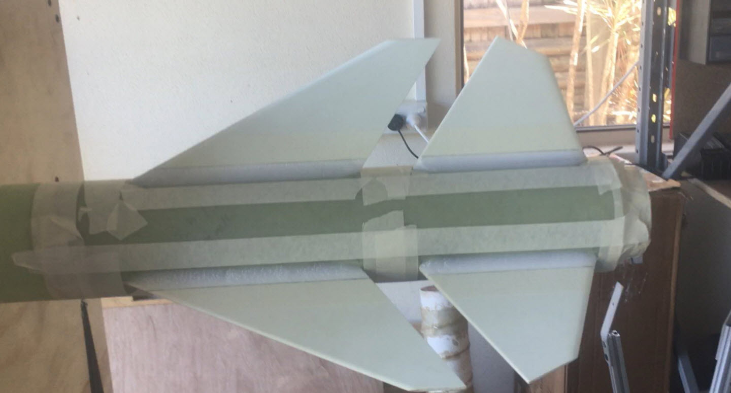
The Payload Switch Ring
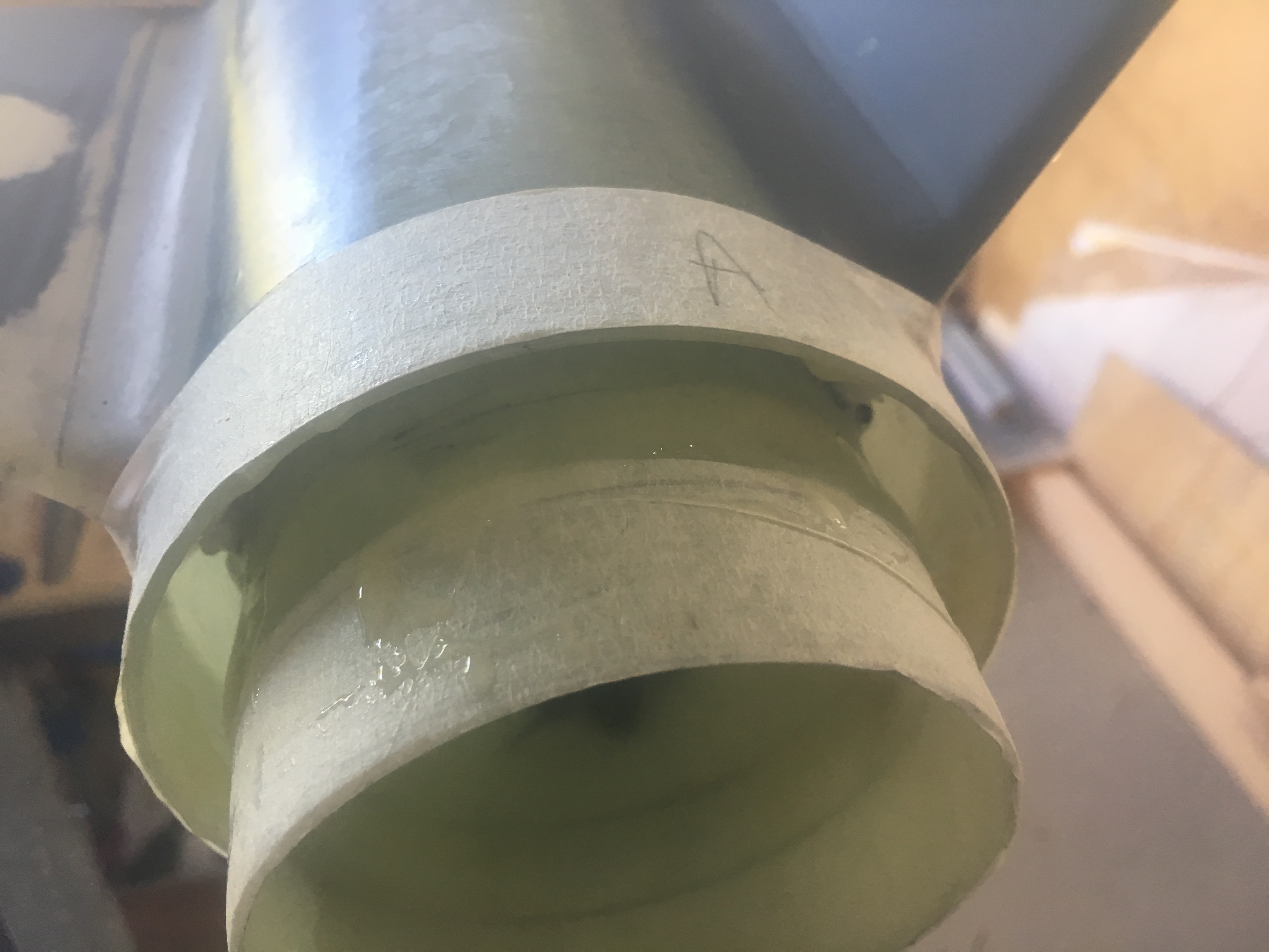
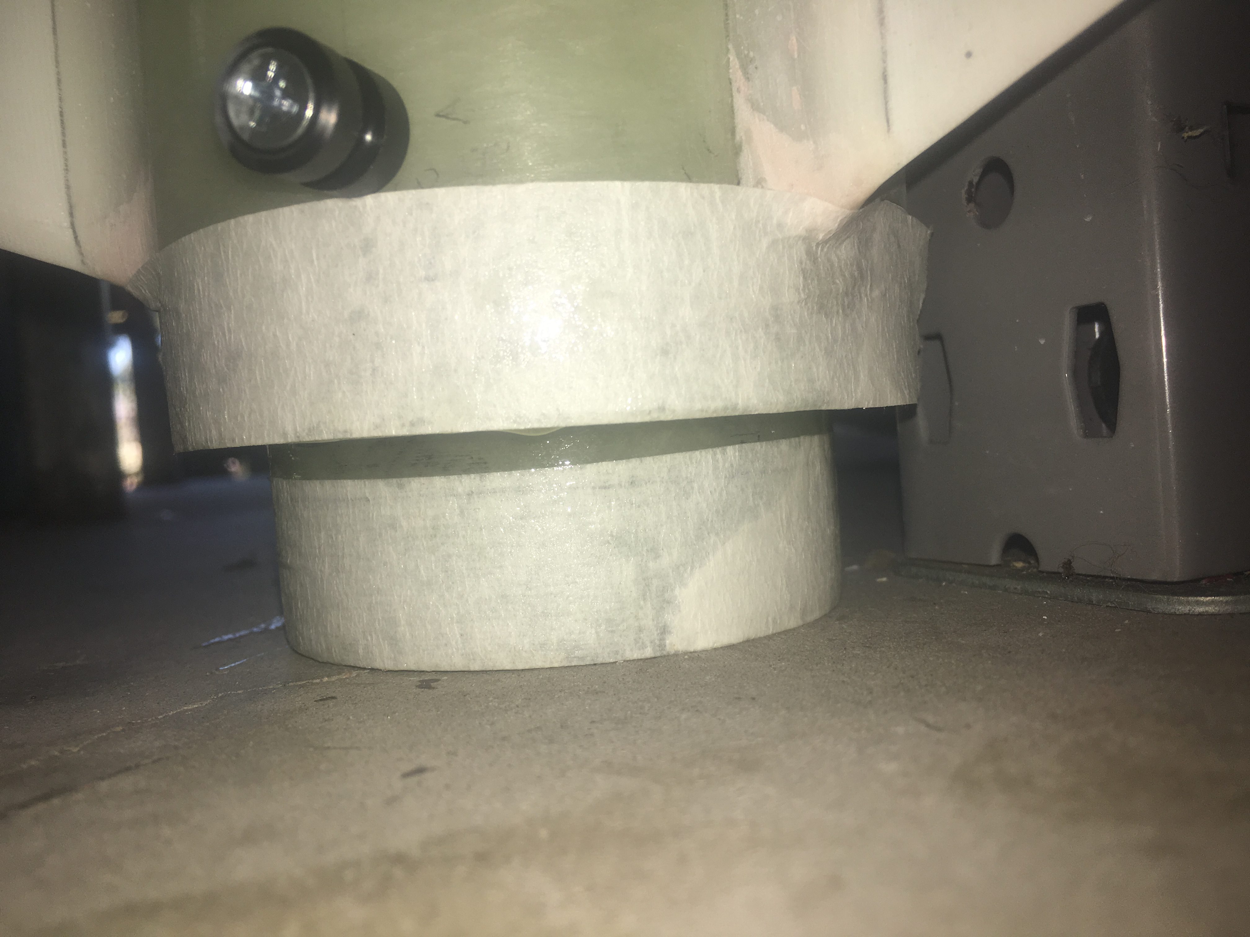
Below are pictures of Payload Switch ring.
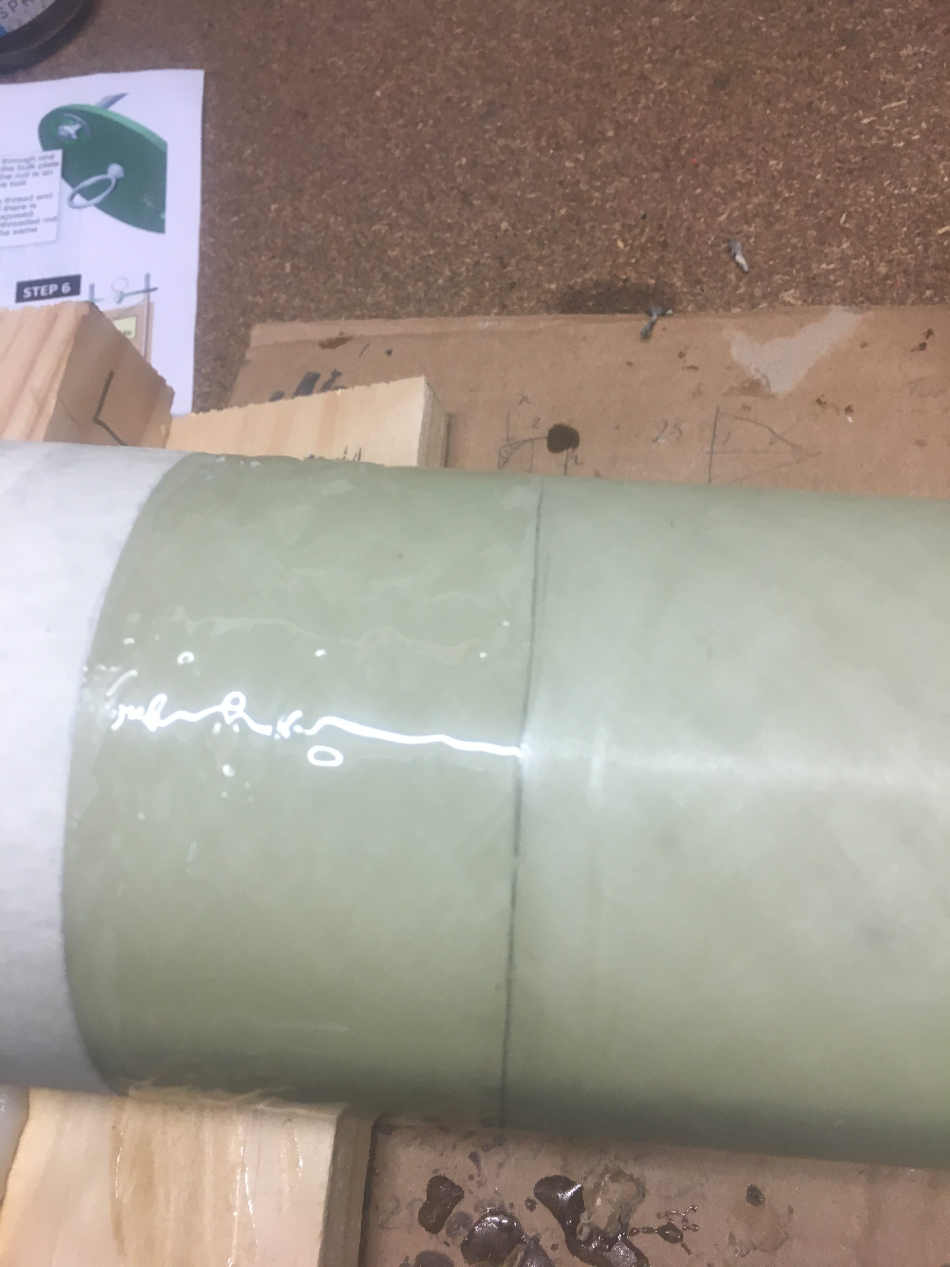
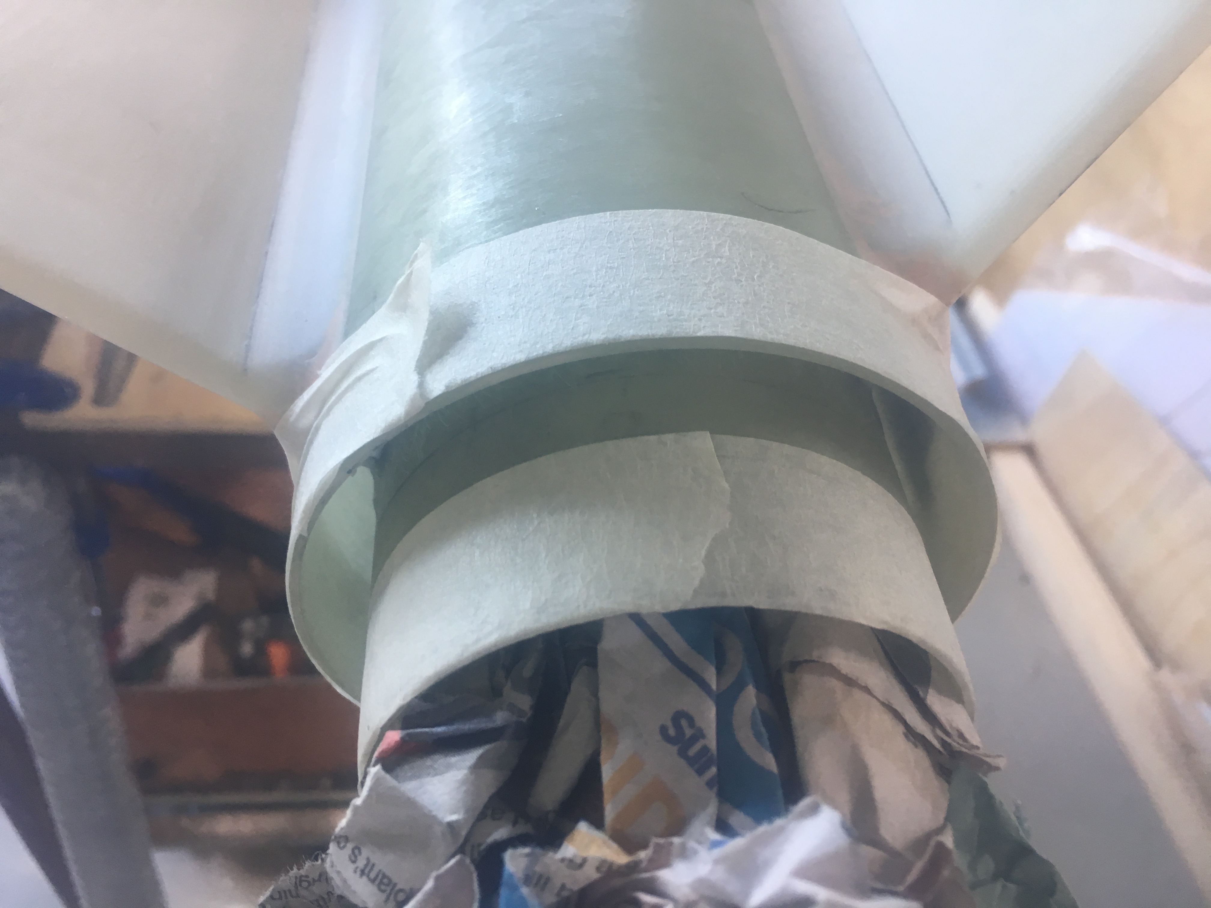
Checking, double checking that the place where the Switch Ring is to be glued is the right spot. Tape is reduce amount of Epoxy getting into places I don’t want it to go.
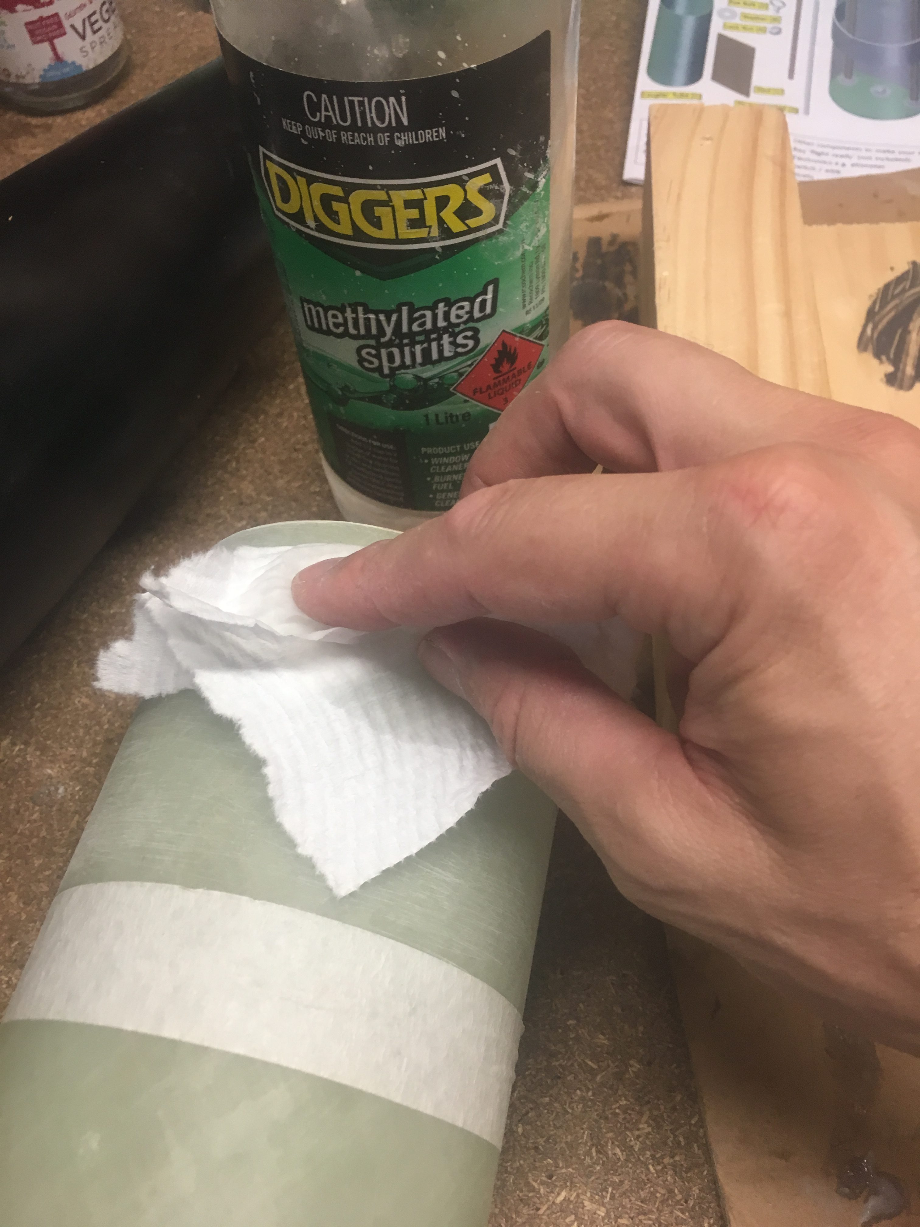
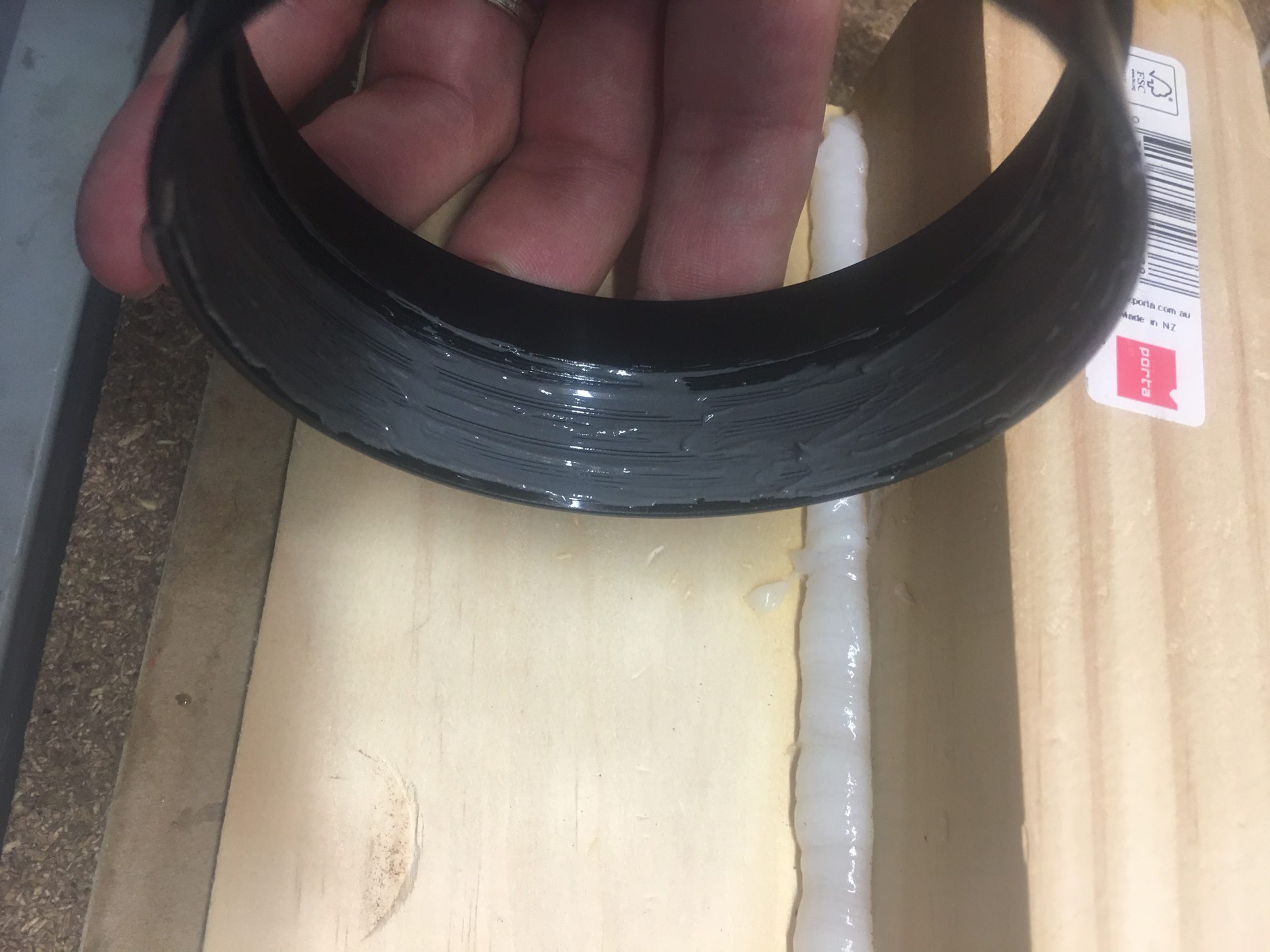
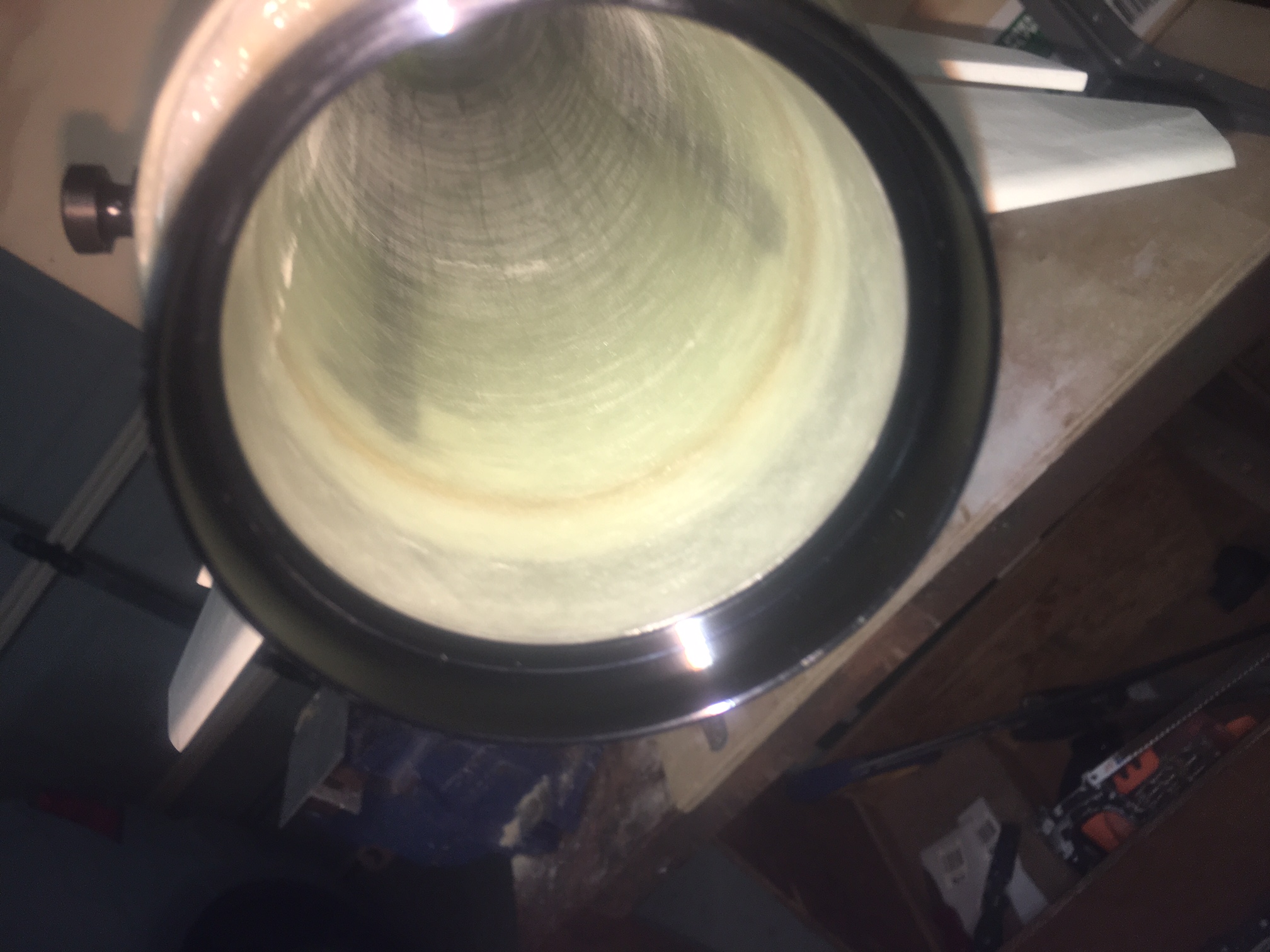
Sanding section where Switch Ring is going to be glued.Cleaning payload coupler prior to gluing with Metho.Mixing up BS Epoxy for Payload Switch Ring.Applied Epoxy to Payload Coupler, to where the ring is going to sit.
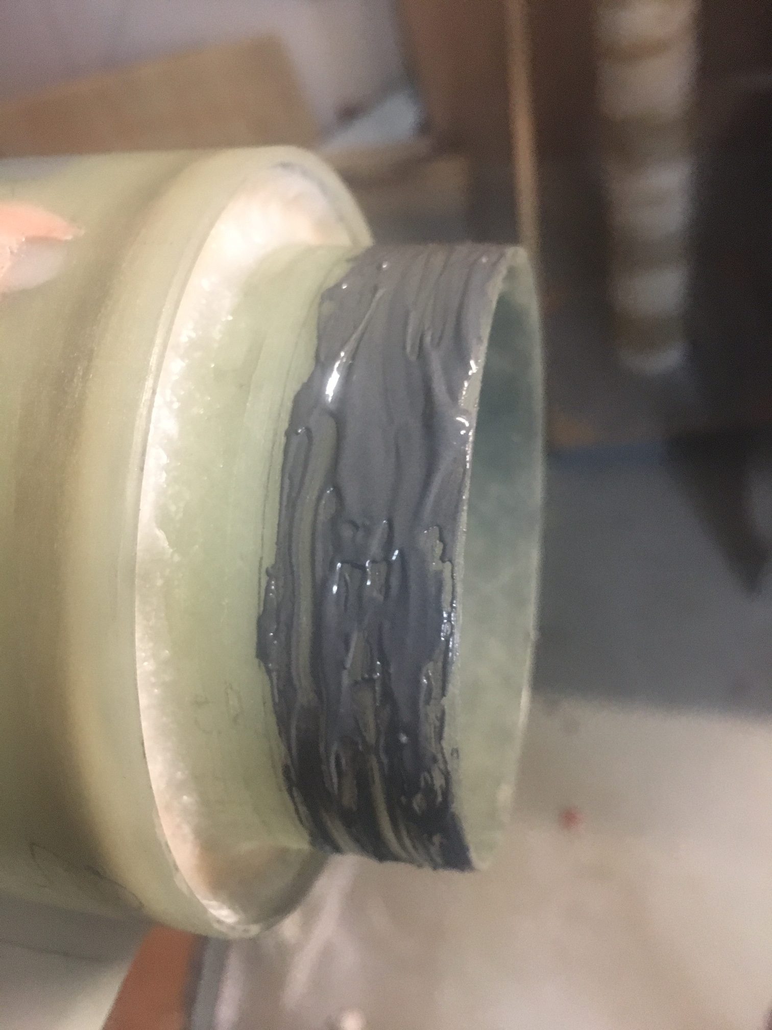
Then we just slid the Switch Ring on, wriggling it a little to ensure thorough epoxy across both surfaces.
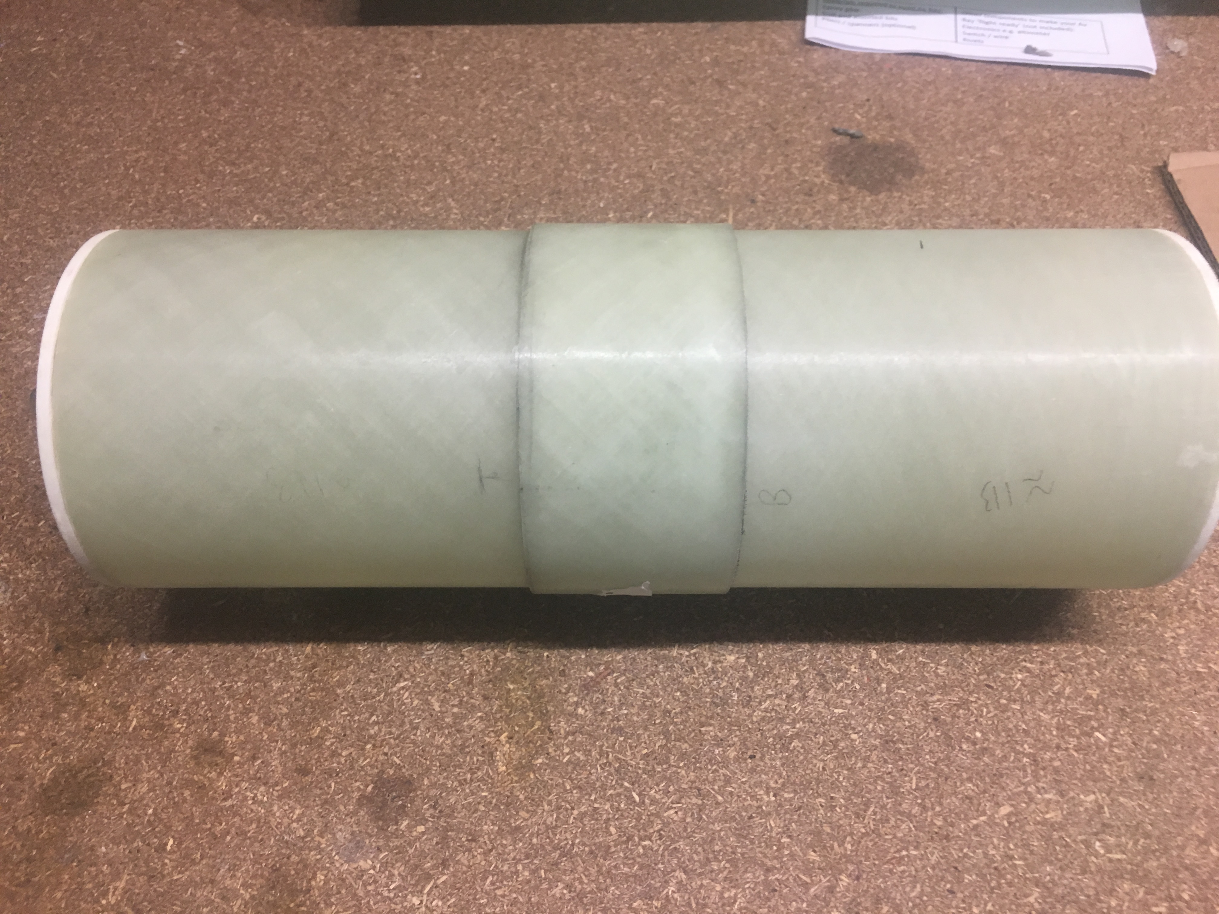
Finished bonding of Switch Ring to the payload.
Nose Cone – Coupler
Masking taped up just area, so when epoxy, reduce chance of it going where I don’t want it to go.Sanding coupler with Grit-60 Sand paper.Cleaning surface before bonding with Metho.Applying Epoxy to inner section of Nose ConeGlued together – just before I removed the tape.
Next step was to glue the Motor retainer on using JB-Weld.
We followed the steps that were on the AeroPak TailCone. The last two in the screenshot below.
Instructions to install retainer.
We needed to use Acetone to clear the internal threads of the retainer component we wish to epoxy to the Motor mount.
Acetone used to clean internal thread of retainer
Cleaning thread of Retainer
Once clean, we make up a generous amount of JB-Weld and mix thoroughly.
Making up batch of JB-Weld for retainer.
Creating a nice thin film of JB-Weld. Getting it into the grooves.
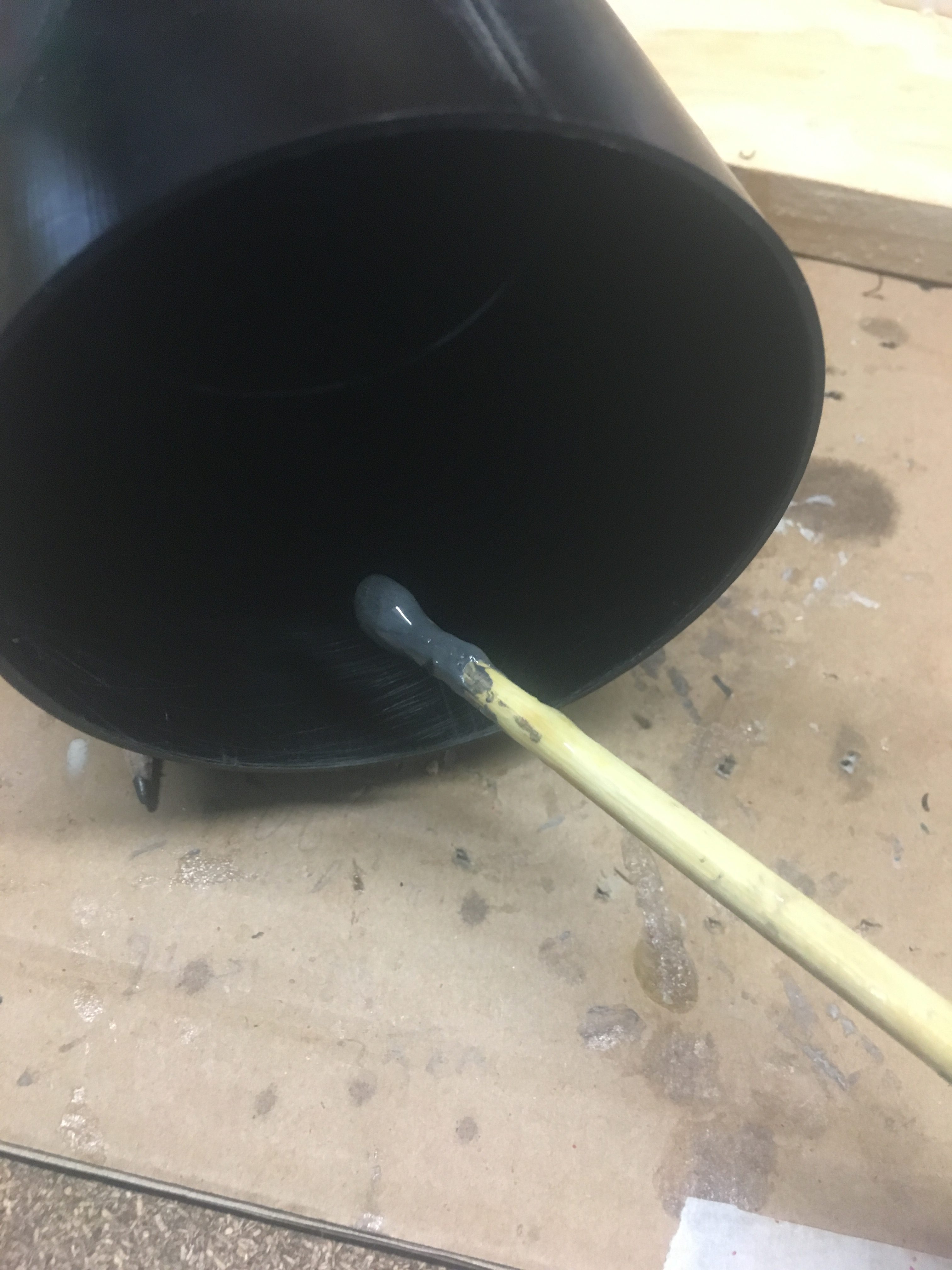
Once done, we add a generous amount of JB-Weld to the motor mount, making sure to keep it to the area that the retainer is going to slide up to.
Getting good coverage of JB-Weld over the Motor Mount.
Then I slid the adapter on. As I slid it on, I turned it around a little, back and forward, in and out to ensure that the JB-Weld Epoxy made good contact.
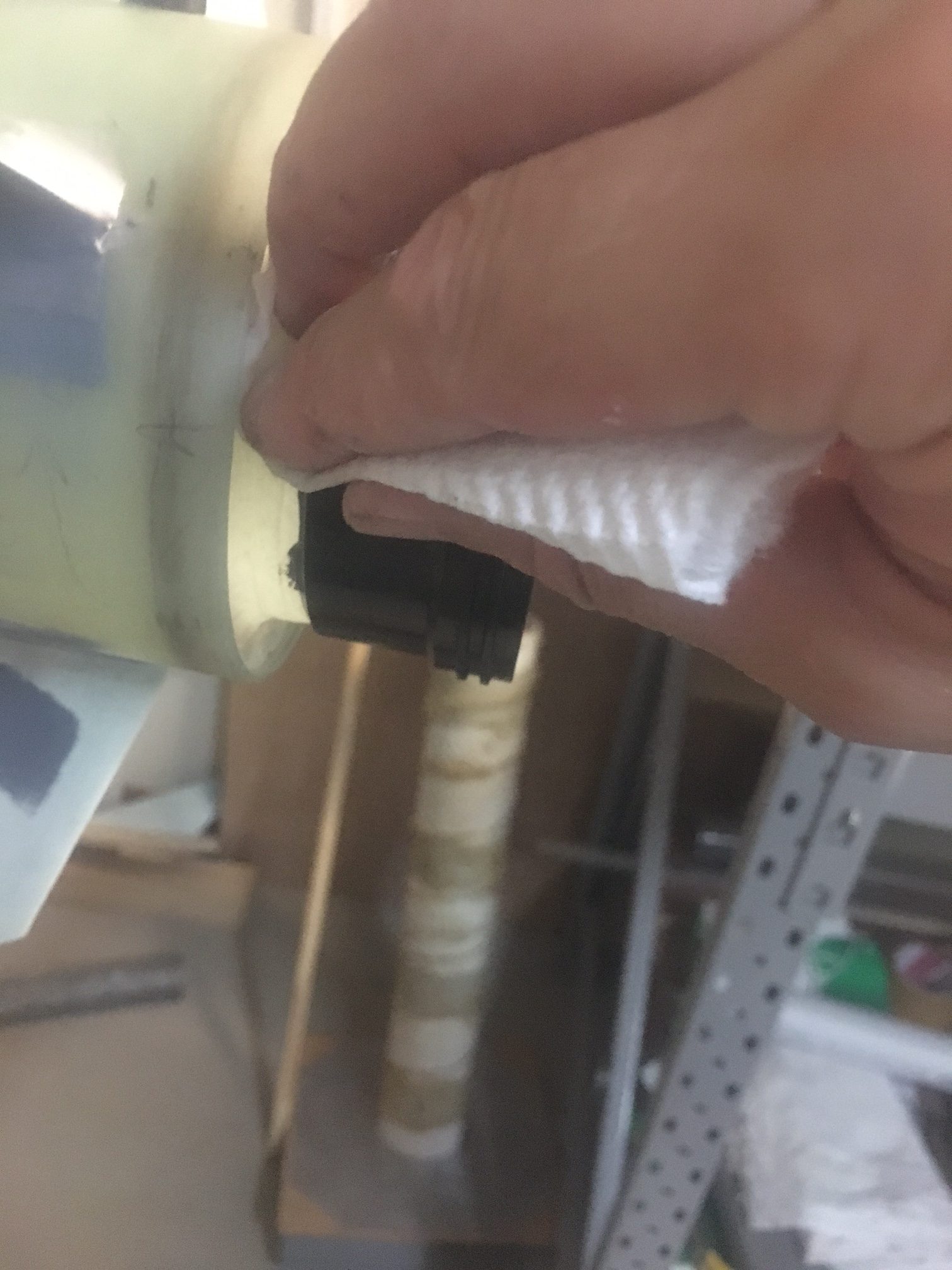
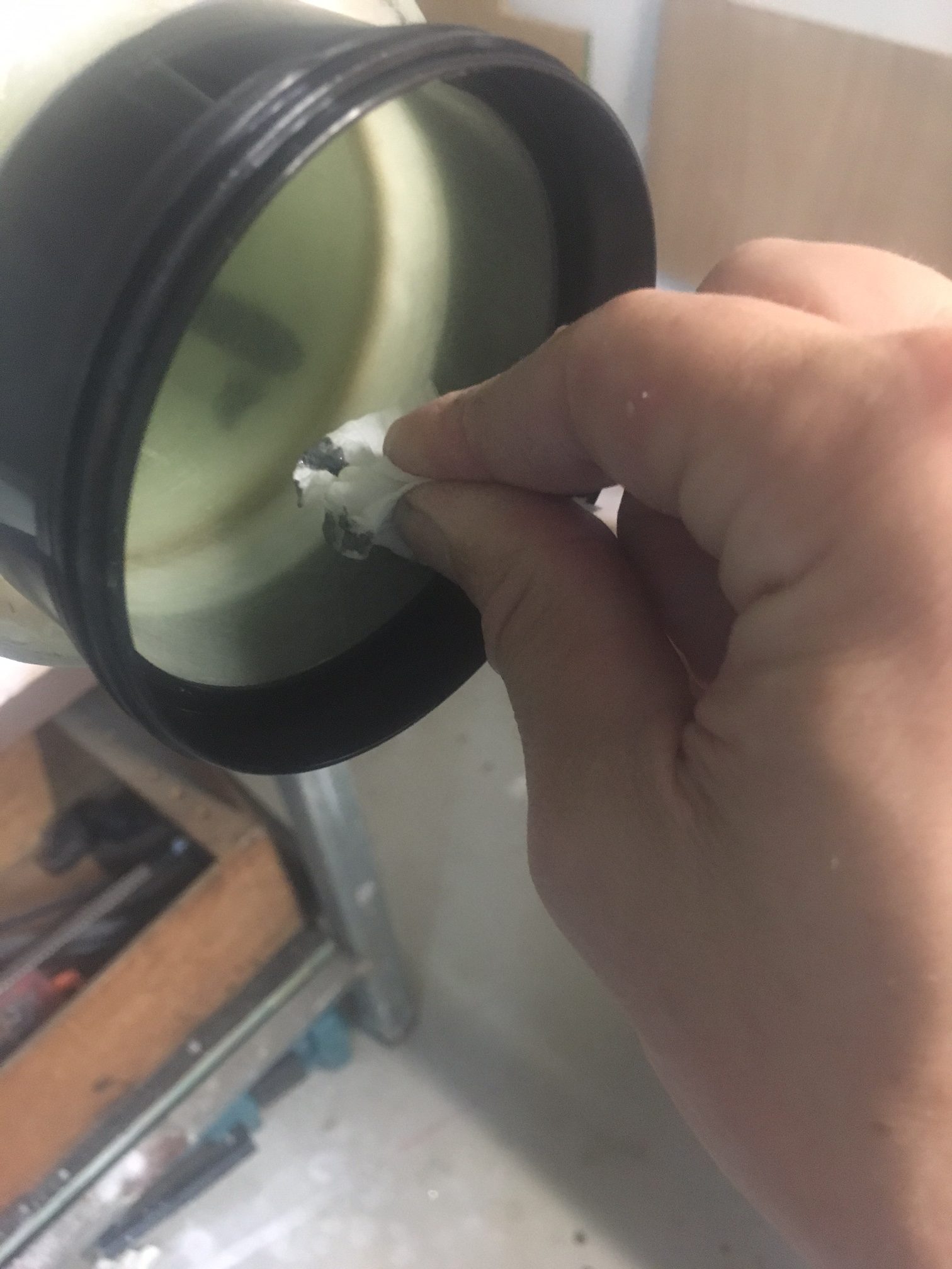
Cleaning off excess JB-Weld
I removed excess JB-Weld inside and outside using paper towel and Acetone.
Cleaning off excess JB-Weld
I checked all around the rocket to see if there was any stray JB-Weld. I made sure that the adapter was butt up against the Motor Mount.
The next step was to glue the centering ring into place.
Decisions
I decided to use 30min Epoxy glue from AusRocketry. I didn’t want to go for 5 minute and I didn’t want to for 24 hour.
Preparation
While every effort was made to ensure glue/mess did not make its way on o the surfaces where the Centering Ring is to be glued, some does make its way and so I had to clean it off. There wasn’t much. I used some Methylated spirits to clean the surfaces as well.
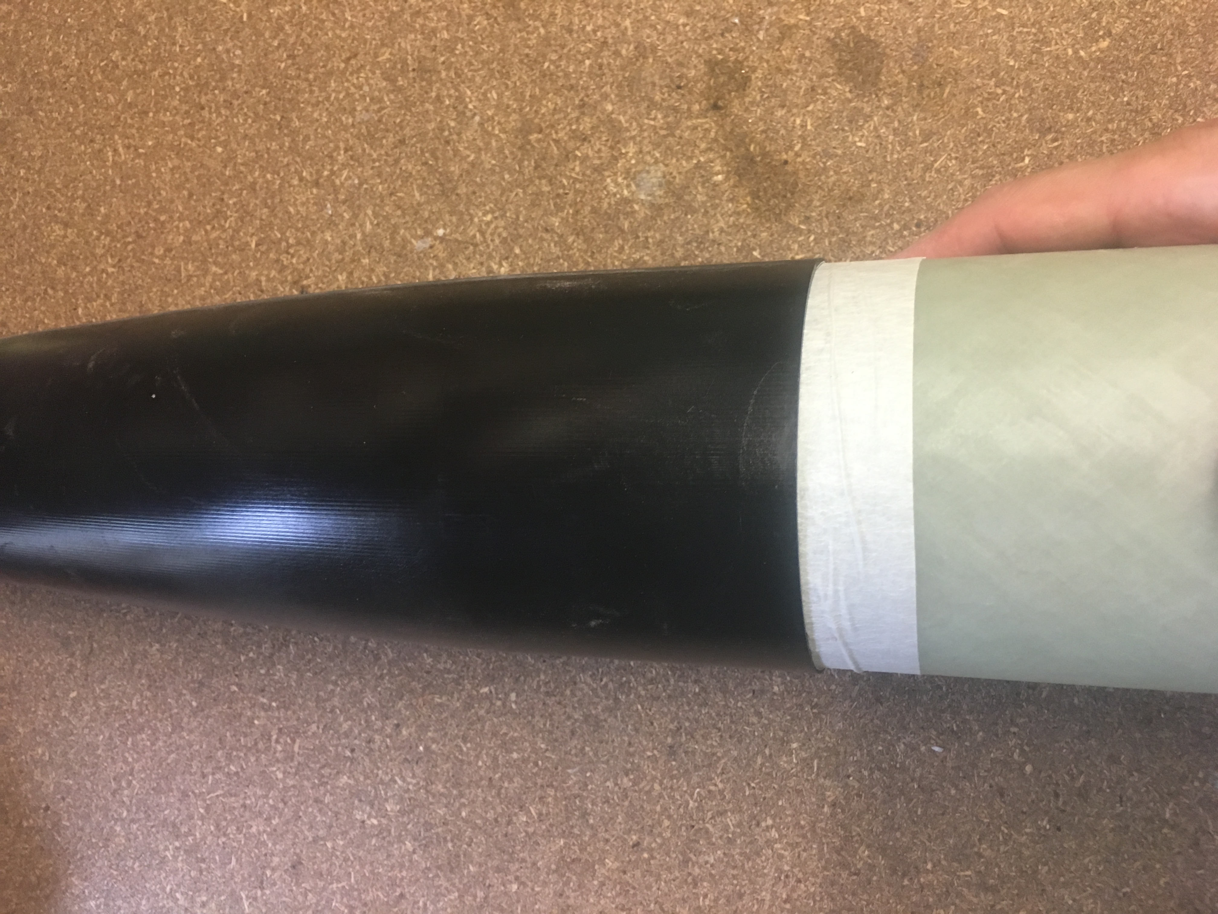
Next I wanted to tape up the motor mount exterior, so I would not get any epoxy glue. I also taped up the exterior of the airframe, just to help reduce chance of getting Epoxy on there.
I also decided to stuff some paper up the Motor Mount tube to ensure nothing got up there.
Insert centering ring in ~6mm and mark on the motor mount three places with pencil. This helps us know how far we have to push it in.
Gluing the Centering Ring
This was a carefully thought out job.
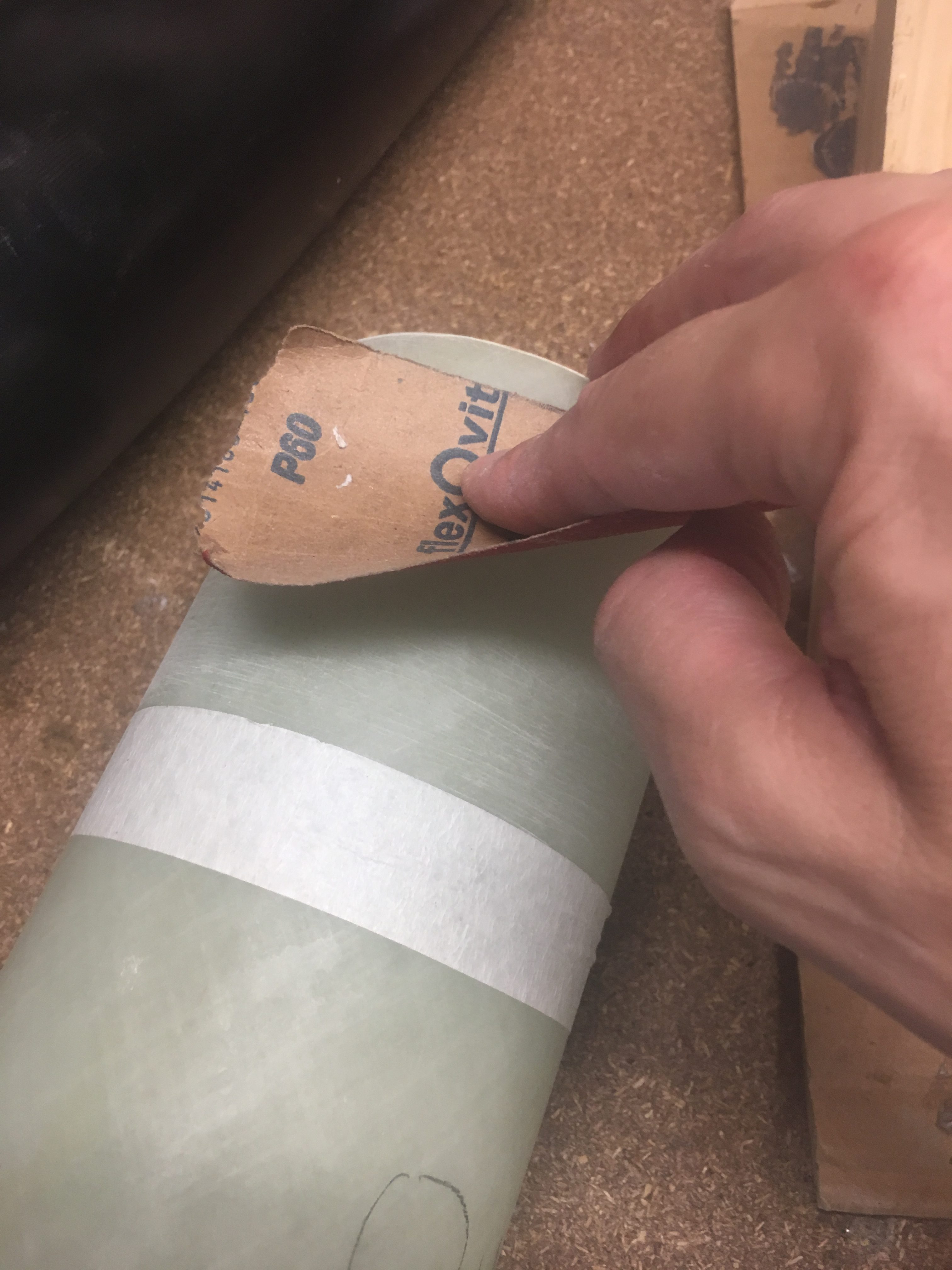
Internal and External ring is sanded with Grit 60
Sand internal/external with Grit 60 sand paper
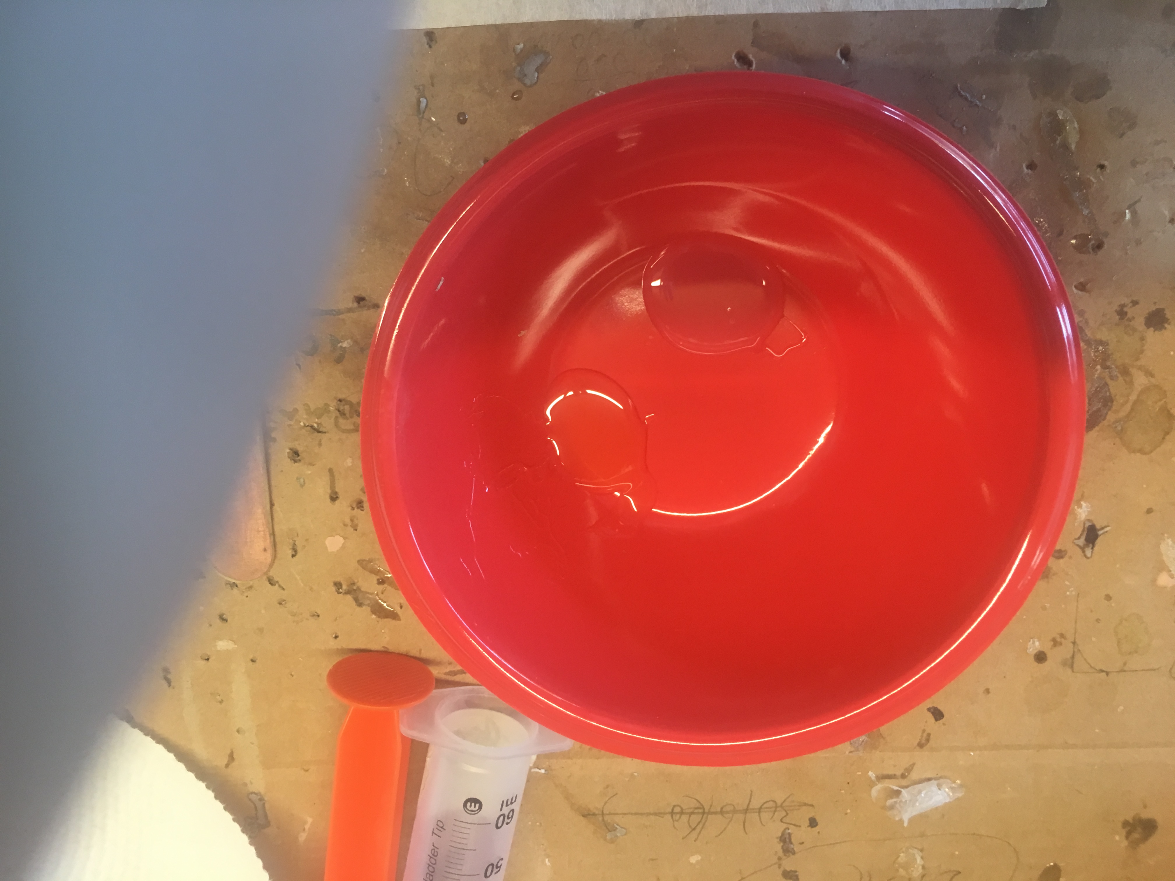
Mix the epoxy resin and hardener
Apply some of epoxy to the external surface of the centering ring. Need to be liberal in application, but not so much it drips too much or make a mess.AS YOU DO THE JOB, rotate the rocket so the glue doesn’t drip down to one area of the rocket!
Apply liberal amount of epoxy on inside of air-frame (a ring)
Apply liberal amount of epoxy on outside of the motor mount (a ring)
Remember, keep rotating the rocket.
Slide the centering ring on
Double check the depth the centering ring has been push in
Remove the wire holding the centering Ring
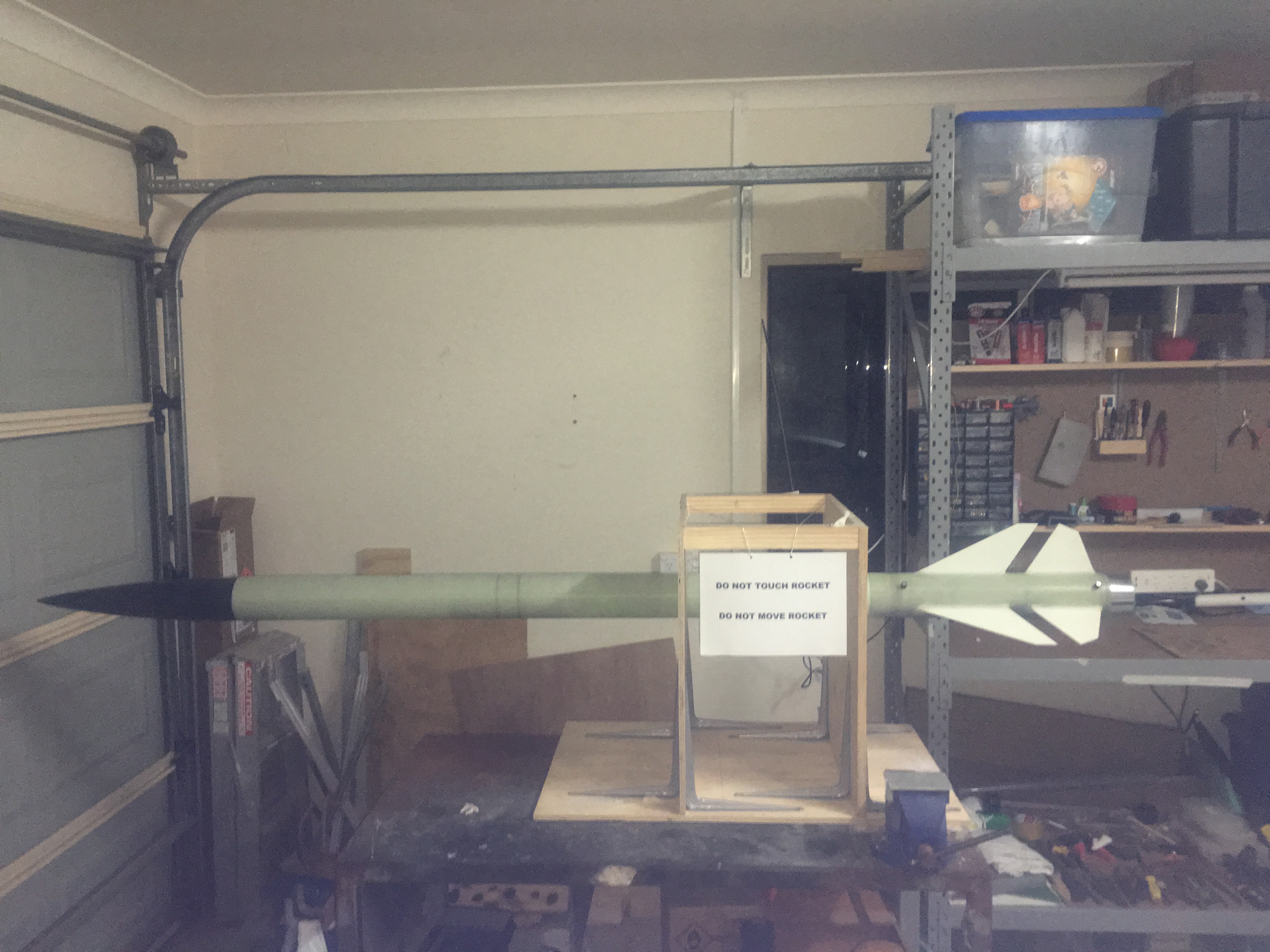
Take the rocket out of the Jig and attach to pole and cable-tie up
Here are some pictures.
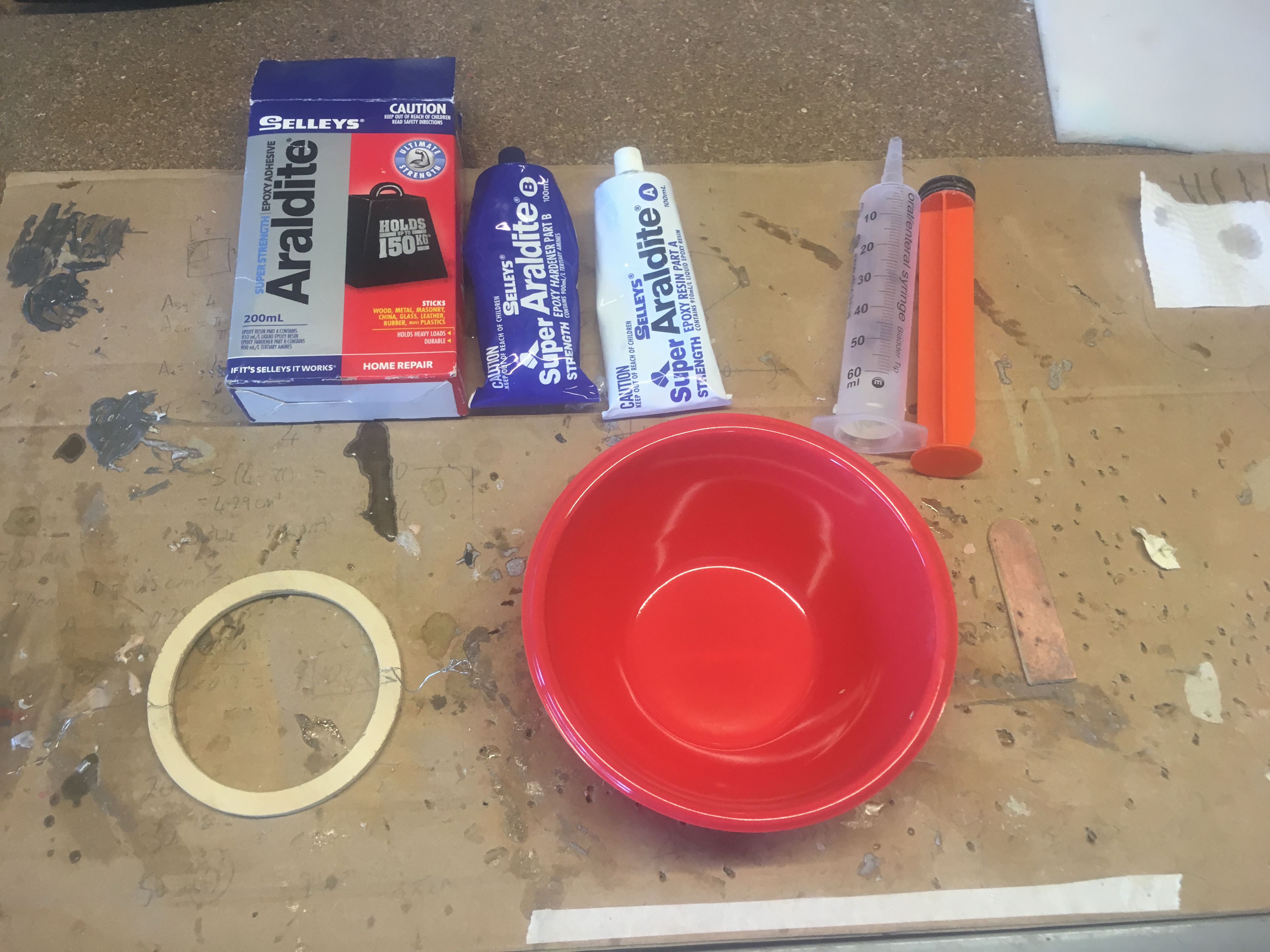
Taped off areas to prevent Epoxy spoiling the rocket.All tools and materials out, ready to go.
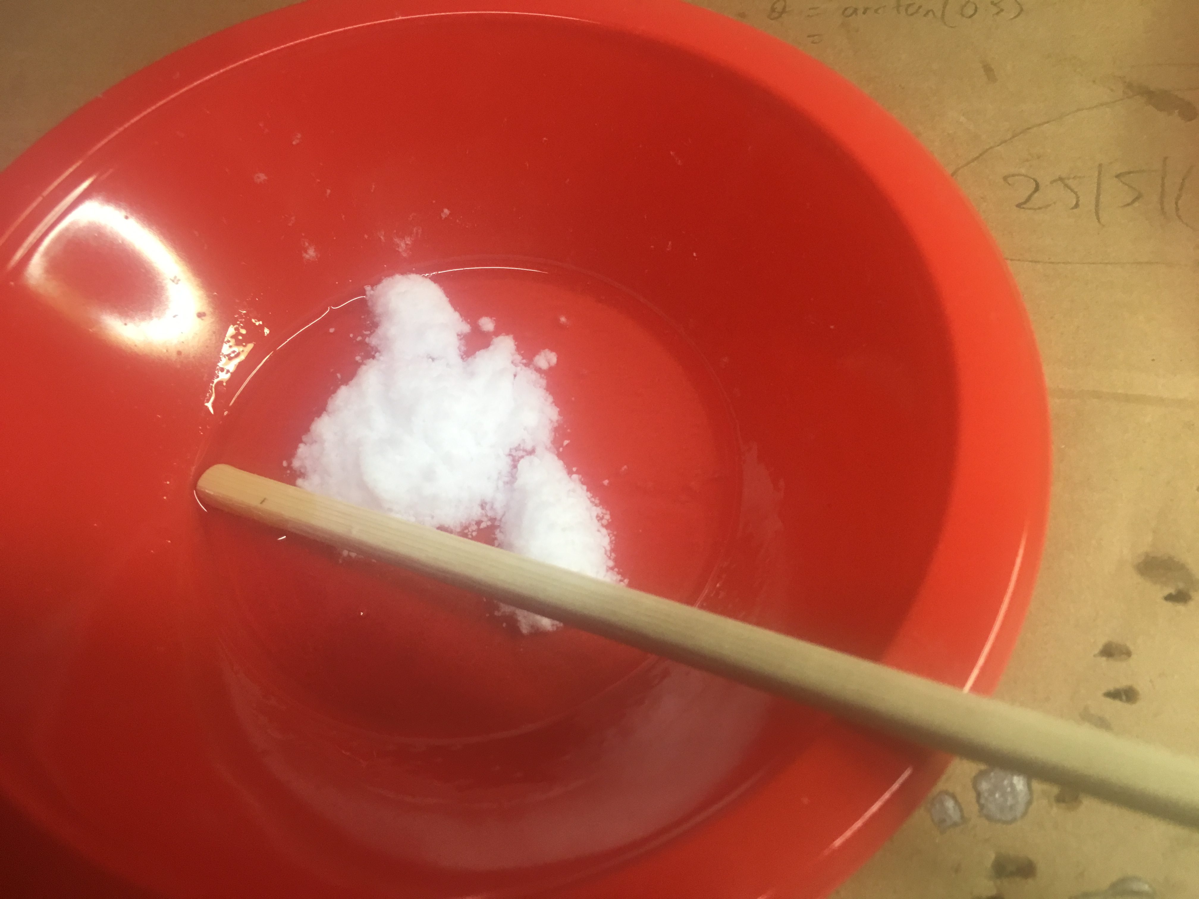
Never used the Syringe in the end. Used chopstick instead.
Mixing 24 Epoxy.
‘Wetted’ the Centering Ring with Epoxy.Applied Epoxy to Motor Mount and Airframe. (Might be hard to see)
After this I slid the Centering Ring on. This requires two hands, so no photos.
Then I erected the rocket against the workbench, so that Gravity would bring the Epoxy on to the top of the Centering Ring.
Rocket strapped to bench with cable tiesPhoto of bottom of rocket while gluing. I removed the bottom tape about 2 hours later.
Next I wanted to attach the Rail Buttons. Rail Buttons are what we use to guide the rocket up the rail. A few decisions had to be made:-
What type of button to use – 1010 or 1515
Where the buttons should be installed
How to affix the buttons – to ensure sturdy install
Deciding What Type of button to use
I’ve heard that using 1010 on the rocket I’ve built has worked well for the creator/designer of the rocket. So why would I not want to go for a 1010?
Firstly, I know that this rocket can get quite heavy with certain motors, and the heavier the rocket, the more I want to be sure that the Buttons are appropriately sized – for the weight. But I wanted to err on side of caution. I’m responsible for the rocket and I have to feel comfortable with the build.
Secondly, I know that the QRS club 1010 launch rail is 1.7 metres and the 1515 launch rail is 3.5 metres. When I do simulations using OpenRocket, I get some rail exit velocities that are below 15ms-1. (15ms-1 is approximately 50feet/second). 50 feet/second is considered to be a good around min safety speed. Yes some people have managed to get away with lower speed rockets, but I want to err on side of caution.
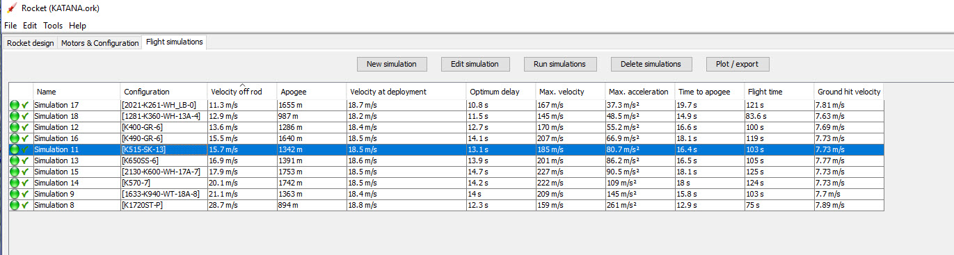
Below is a simulation of some motors using a 1.7 meter launch rail.
Simulation of a set of 54 mm CTI motors using 170cm Rail.
A second restriction I have at the QRS Cedar launch site is that the Ceiling height is 5000 feet. This translates to 1524 metres. With a 10% safety margin, this comes down to about 1372 metres. This means the only real contenders ar:-
K1720ST-P
K515-SK-13
1633-K940-WT-18A
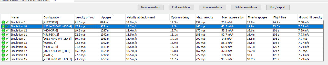
By having a 3.5metre rail, all Velocity off Rod are acceptable.
Simulation of a set of 54 mm CTI motors using 350cm Rail.
The downside of having larger buttons is increased drag – and slightly less sleek looking rocket. Also, if I take the rocket to a launch site without a 1515 rail, I’m going to have problems!
Where the buttons should be
I decided to accept the button placement suggested in the Katana 4 Build instructions, which is 3cm and 45cm from the rear of the airframe. Having the button at the rear means less chance of taking paint off the rocket while loading on to the rail. The 45cm is not the most ideal position (not around CG), but it has to be here because we don’t want the button screw snagging the Drogue parachute. (At 45cm, it is within Motor Mount/Airframe cavity.
How to affix the buttons
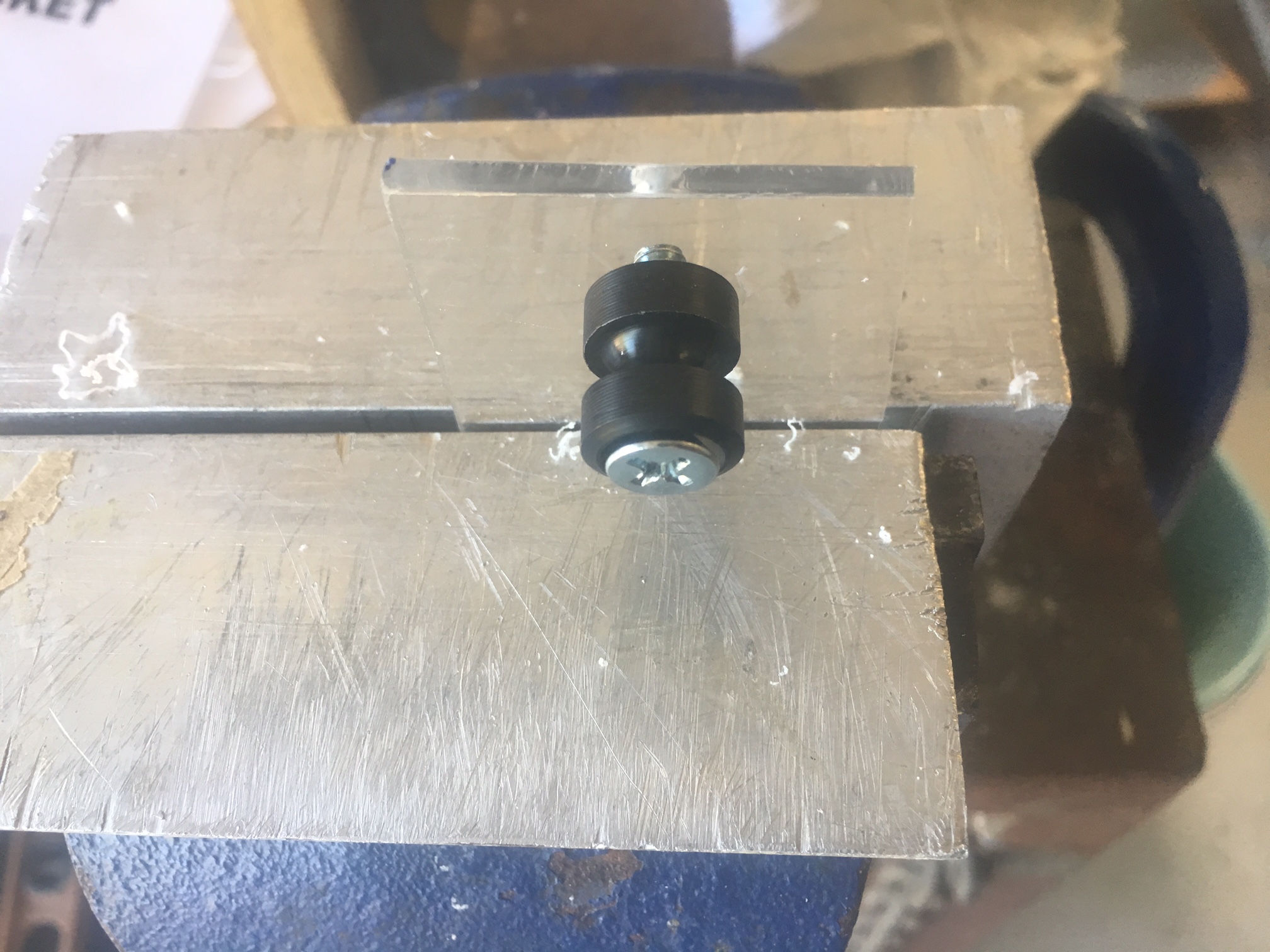
Decided to screw into 4.5mm holes that were very carefully drilled. I added Selleys non-drip superglue (CA glue) into the hole to give the whole arrangement a little more strength. Don’t just want them popping out. I was careful here to ensure that no CA glue was on the exterior which might glue the button to the air-frame. I read that it was important to allow the button to rotate freely.
I was a little concerned that the glue might dry very quickly before I had completely screwed the screw in. So I did a test run. No issues occurred during the test run.
Doing a practice drill/screw run into some perspex.
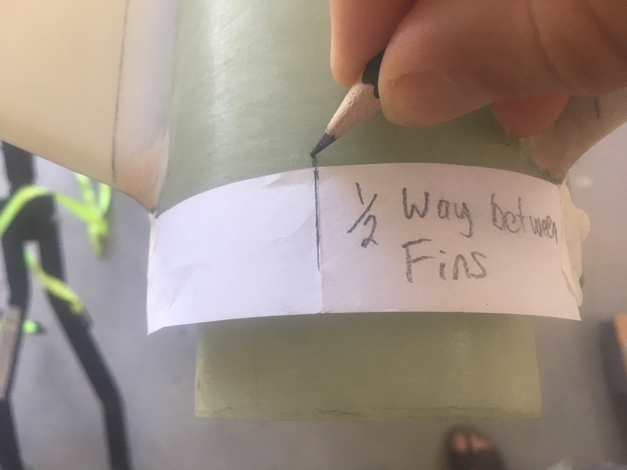
I wanted to make sure the buttons were mid-way between two fins.
Ensuring button install axis is equi-distant from each two adjacent fin-sets.
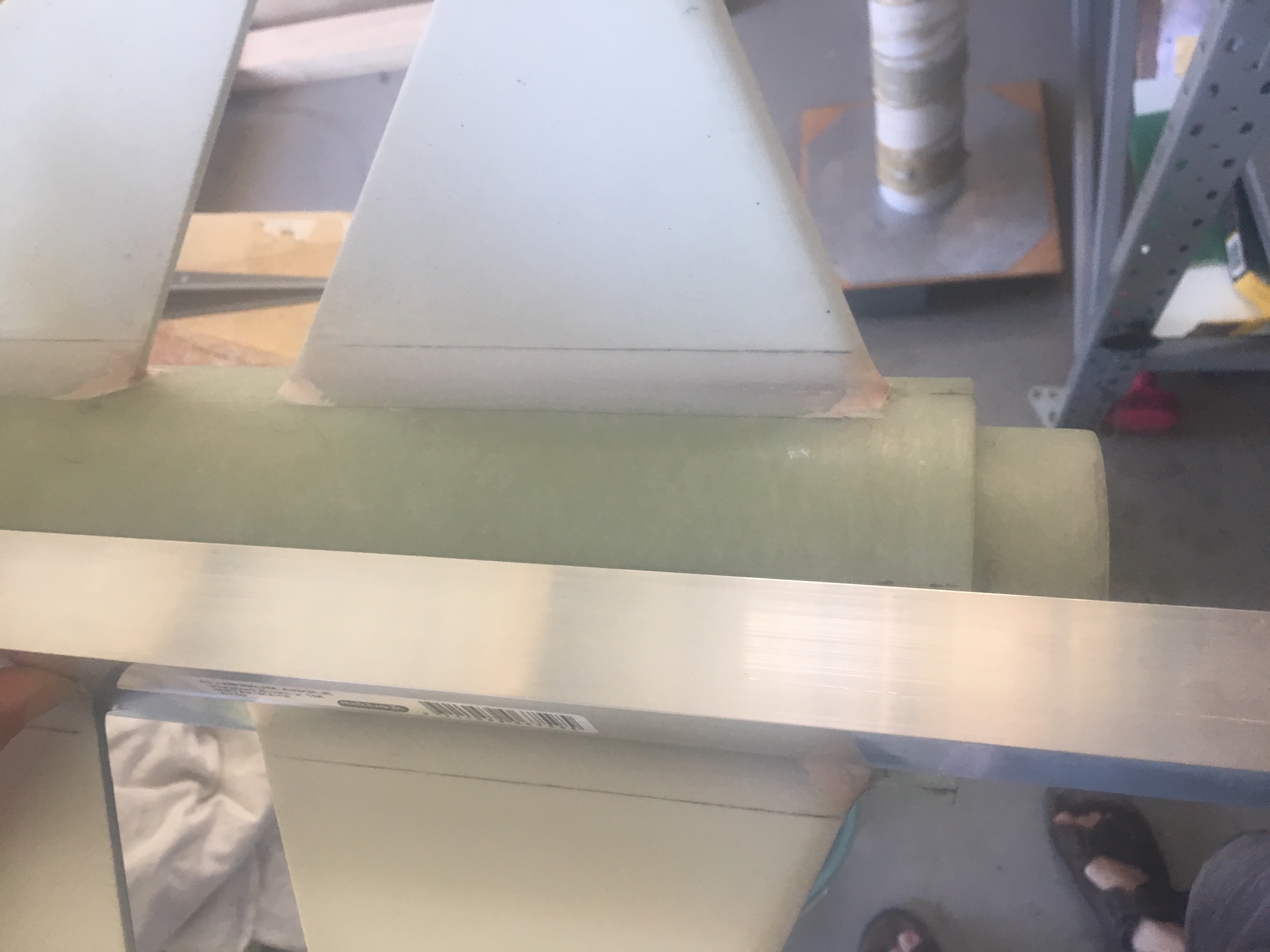
The first part of install was to mark the places to drill. I used Right Angle aluminium length and pencil.
Angle Aluminium to help mark drill holes for buttons.
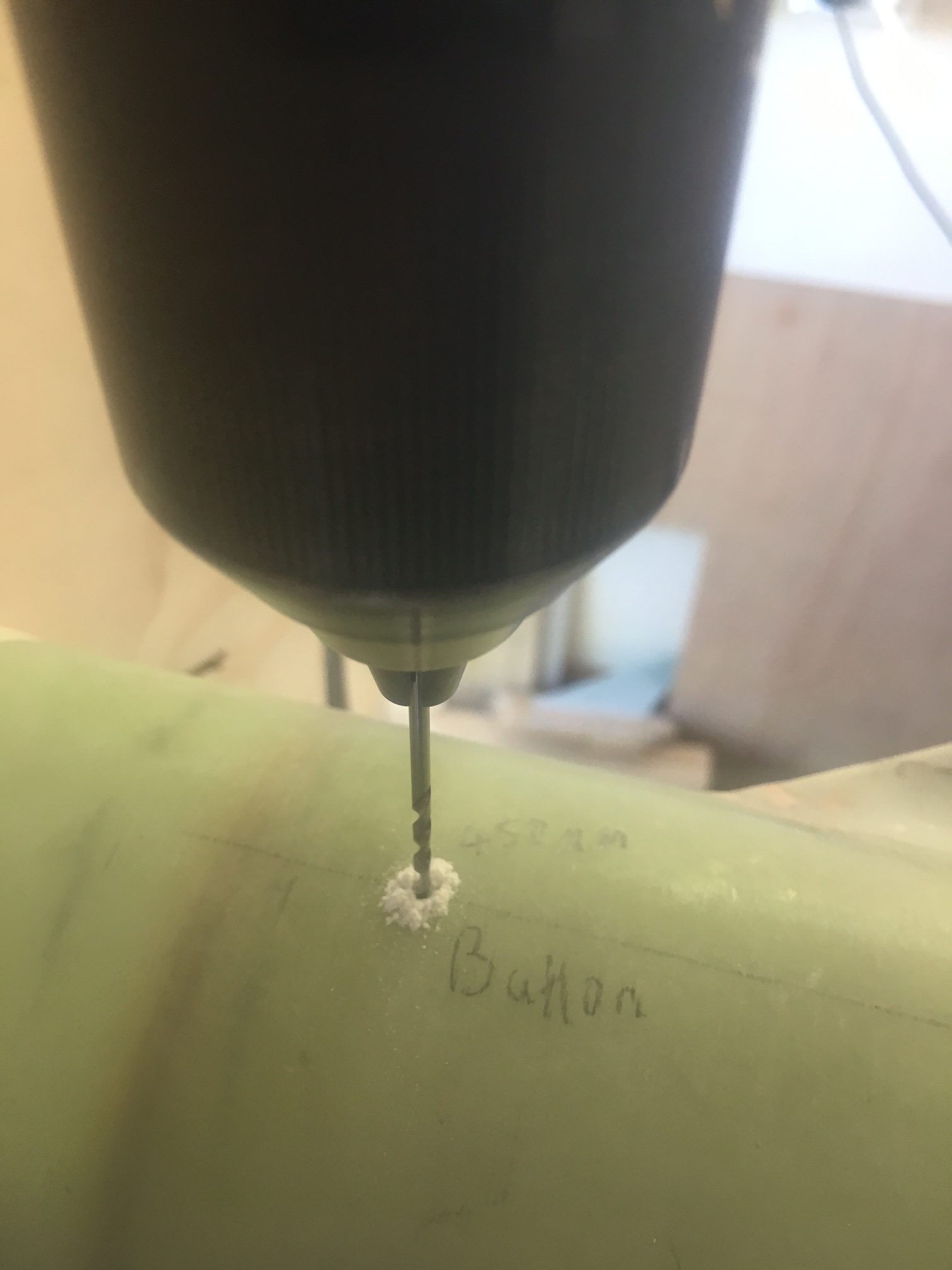
I drilled holes very carefully making sure the drill bit was perfectly vertical. I drilled the initial hole at 2mm. Then used 3, 4 and finally 4.5mm drill bits.
Drilling holes into Airframe.
As you see, I carefully labelled every area I was to drill, double checking measurements before drilling.
Here is how it looked at the end.
Rear button is installed.
Forward button is installed.
I was careful to make sure the buttons could spin,
After the buttons were installed, I put a dab of 105/206/403 epoxy on the inside on the screw. Here is how the rear screw looked. Not pretty, but it helps to take some of the load.
Eventually I applied the final External Fillet Epoxy to the air-frame. They all looked reasonably good, all quite similar in profile and size to the photo below.
View from back of both fillets.
Preparation
I wanted to avoid sanding the air-frame and fins at all costs. I decided that if I employed masking tape, I’d have to sand through the masking tape before sanding the fins/air-frame and I’d notice in time that I was sanding the wrong thing. Below is a picture of it all taped up.
Taped up and ready for sanding
Sanding
The next step was to sand them. I had gone to extraordinary lengths to glue Sandpaper to a long stick to sand the fillets. I realised pretty quickly that this was overdo and I did not need along sheet and I did not need a long stick. In-fact, having a long doweling with long strip of sandpaper was counter-productive because the fins, even though they were VERY well aligned, the slight differences in epoxy between Fore/Aft fins meant that the sand paper would not reach all along the whole length of the fillet. The other fin was “in the way”.
So I pretty quickly went for a smaller doweling with about 10 cm of Sand paper just wrapped around it with some masking tape to hold it in place at one end. This allowed me to sand each fillet individually. No glue, it was so much easier.
I used the following sandpaper in the order shown:-
Grit 60
Grit 240
Grit 600
Grit 1200
I used water for Grit 600 and Grit 1200. i.e. Wet and Dry.
I had to be very careful to keep the doweling parallel to surfaces, to ensure I produced a curved profile along the whole length of the external fillet.
The results
The results were good, but not as impressive as I had hoped. Near the edges of the fillet there were craters. I couldn’t risk sanding into the air-frame, so I had to think about how to deal with them.
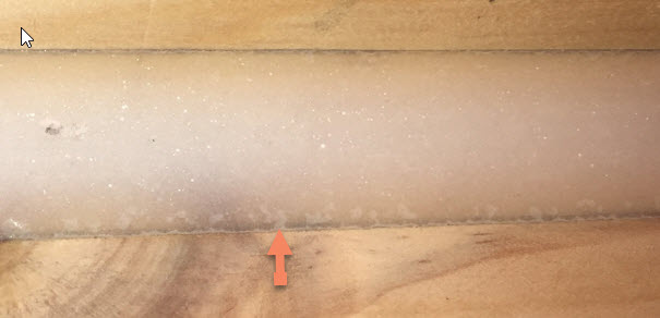
I didn’t keep a photo of the cratering, so I’ve retrieved a photo of cratering in some of early practice fillets.
Cratering on bottom of external fillet. Red arrow pointing to the cratering.
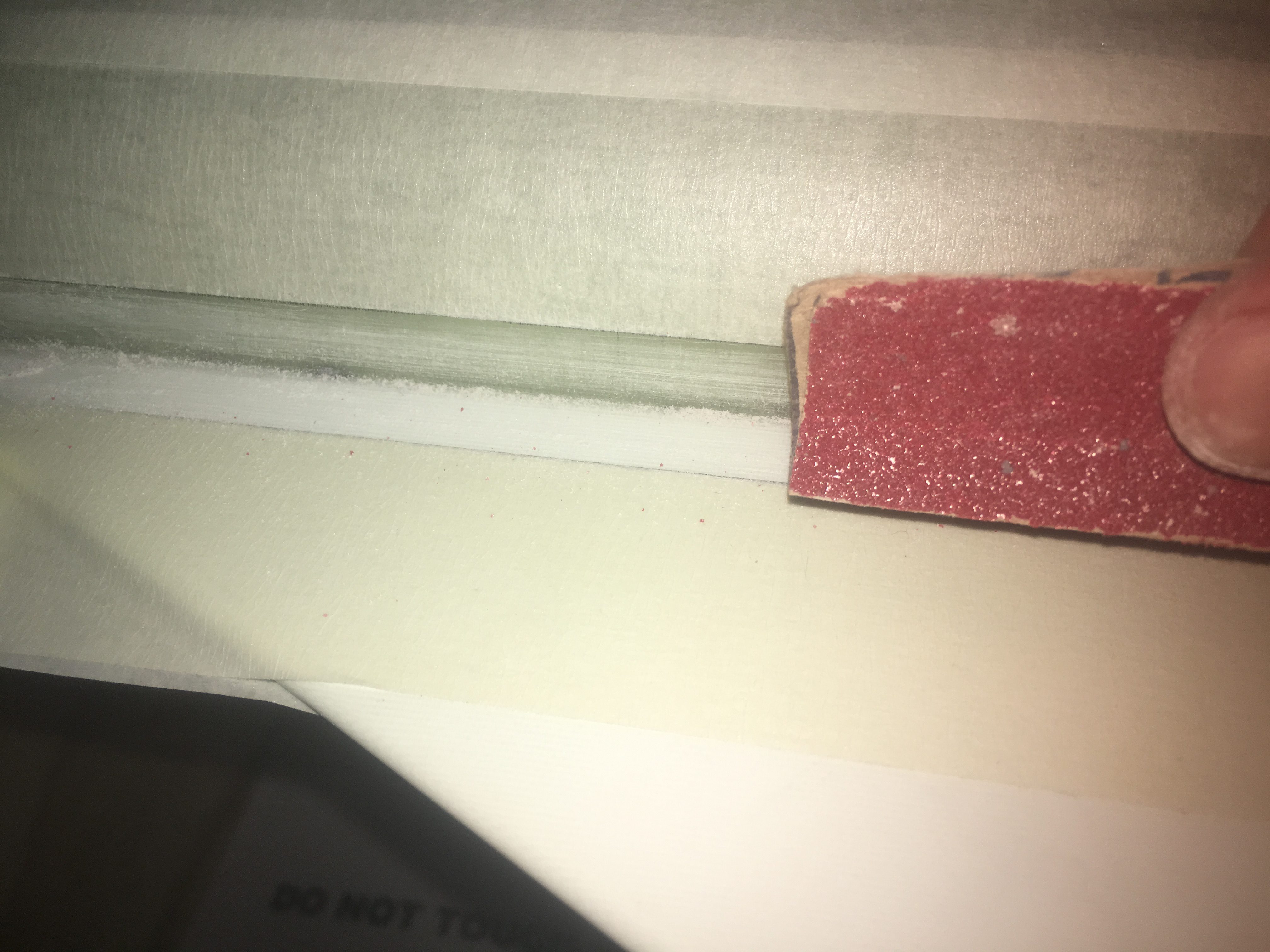
Preparation is key to the success. I made sure we sanded the areas to be filleted with Grit 60 Sand paper, that they were then cleaned with Methylated spirits and then taped up.
Sanding with Grit 60 Sand paper.
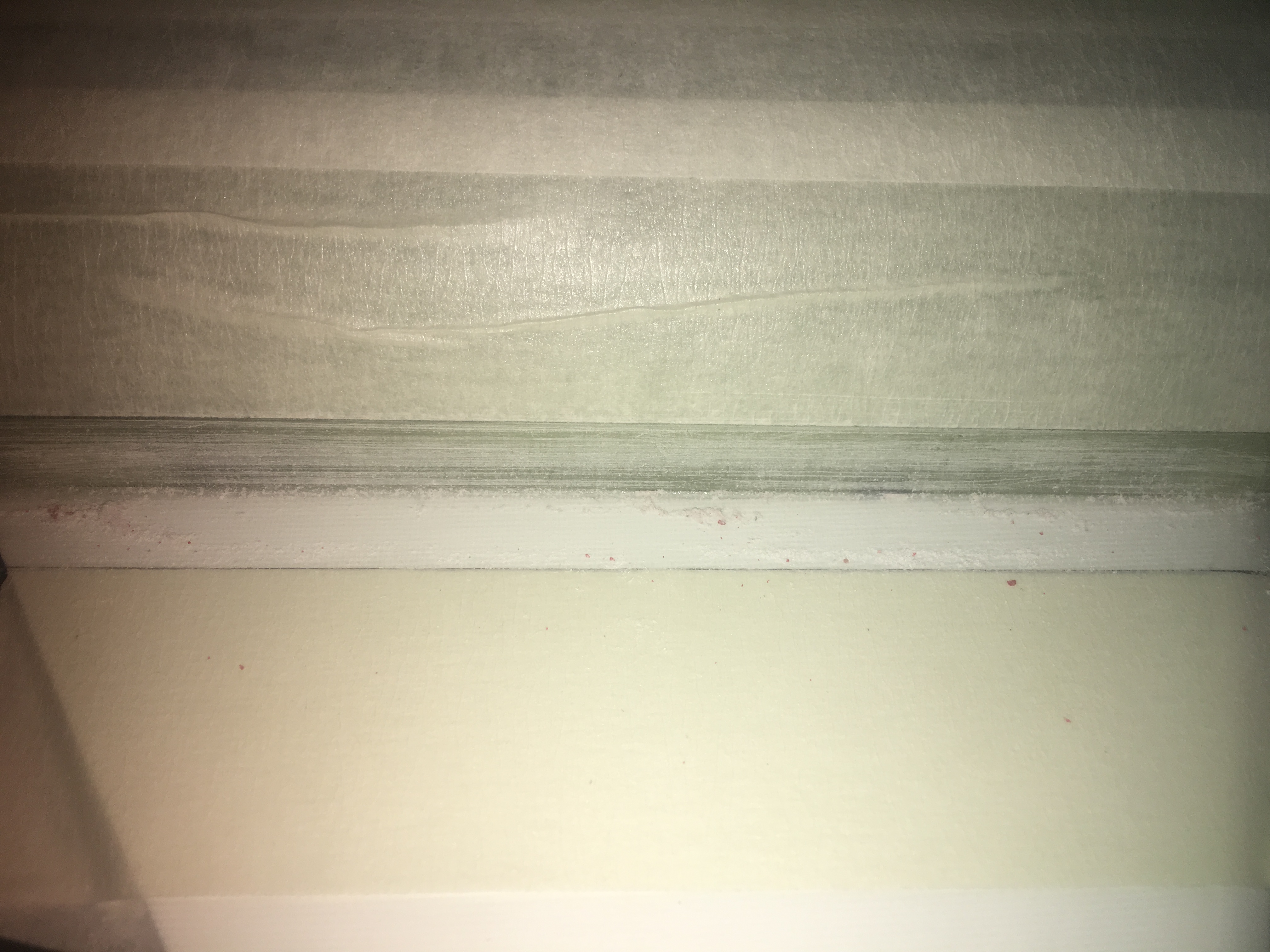
Finished sanding – ready for cleaning.
All practice external filleting I had done so far had neglected the ends; it was more focused on the the main stretch. The width of the fillets needs to converge to zero at both ends of the fin on the air-frame. I did a simple plot y = 2x^2 on my printer and printed it out and used it to create masking tape pieces to stick at the fin ends. What resulted looks as follows:-
Pointing to the curved masking tape end. This should ensure a consistently shaped fin fillet.
Rocket all taped up, ready for filleting.
The Glue
We made a normal ‘peanut’ consistency batch of Epoxy. We decided to use the new syringes as the old ones are too sticky and hard to push.
We originally made 20ml/4ml of epoxy for one one side of fins (lower and upper fins). We found that there was probably about 6ml of epoxy left over – so wastage. In future Epoxy runs, we’ll make it up using 15ml/3ml of 105/206.
Epoxy in new syringe, already to go.
The result
Back fin.
Front FinView from back of both fillets.
Fairly happy with it. I am going to need to build up the back/front of fins to ensure smooth transition. Not quite as good as I had hoped there.
I decided after much internal debating to create a fillet between Fin and the air-frame. (Though it is more from the previous fillet to the air-frame). I decided to do this because the instructions for Katana 4 mention Internal fillets to the Air-frame. I know some people don’t bother with these fillets and I can probably get away without having them for smaller motors. But if I want to fly larger motors or lots of flights I might experience issues with fins/air-frame.
So much focus has been on attaching the fins securely to the motor-mount and air-frame that it is easy to forget other possible modes of failure (other than fins coming off). I was a little concerned that the air-frame, being as thin as they could possibly fail due to loads. So I thought it would be prudent to strengthen the air-frame around the fins with this fillet.
The Epoxy resin
I decided I didn’t want to go through with the 105/206 again with leakages. The space is much more restrictive and so bogging up ends could be difficult. The fillets don’t need to look nice and so I decided to go for 105/206/403 – just short of peanut consistency. I decided to go a little under peanut consistency, so that the epoxy could ‘droop’ down and fill up the gaps. I wanted a droop more than a drip so that I wouldn’t get a large mess. After about 20 mins of curing, it’s viscosity increases sufficiently that it stops drooping.
The tools
It was too hard to use really thin tube – 5 mm in diameter, despite the obvious advantages; it can easily fit down into the cavity. The problem is that the Epoxy cannot be easily delivered due to the viscosity.
So I had to go for 6 mm internal diameter tube. The extra mm makes a big difference. A problem with 6 mm tube is that I couldn’t attach the normal doweling to get it down into the cavity. It just won’t fit. 6 mm tube by itself is so snug that it somewhat deformed (squashed a little). I also wanted an arc (1/4 circle bend) at the end to direct the epoxy into the gap between the air-frame and the fin and the only way I could do this was with 3 mm diameter copper rod that I bent into shape. I used narrow lengths of Masking Tape to bend the tube at the end to the copper rod.
6mm Internal diameter plastic tube on 3mm copper rod.
It worked! I could then withdraw the tube and push the epoxy in and was even able to just see the epoxy coming out, so I could confirm that it was going into the right place! Very happy with this.
Preparation
Bench ready for Gluing.
403 Filler ready for use.
Mixing 403 filler into 105/206 mix.
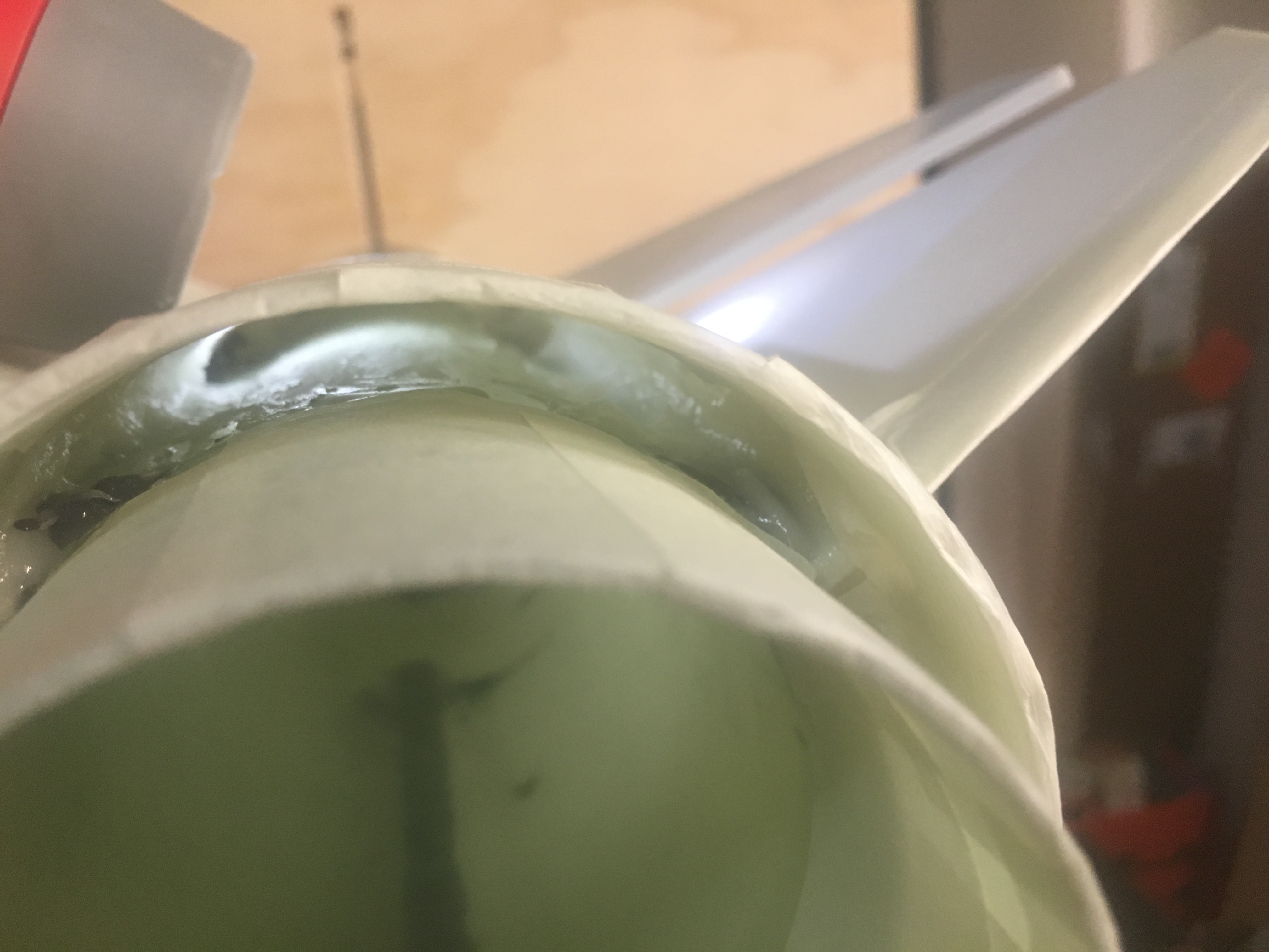
Internal fillets done
It is a bit hard to notice, but there are internal fillets done here.