Preparations for next model rocket launch

A lot of work has been done constructing the payload and programming the micro-controller. Preparations are now underway for the next model rocket launch.

Below is a picture with everything assembled.

Payload assembled into Rocket

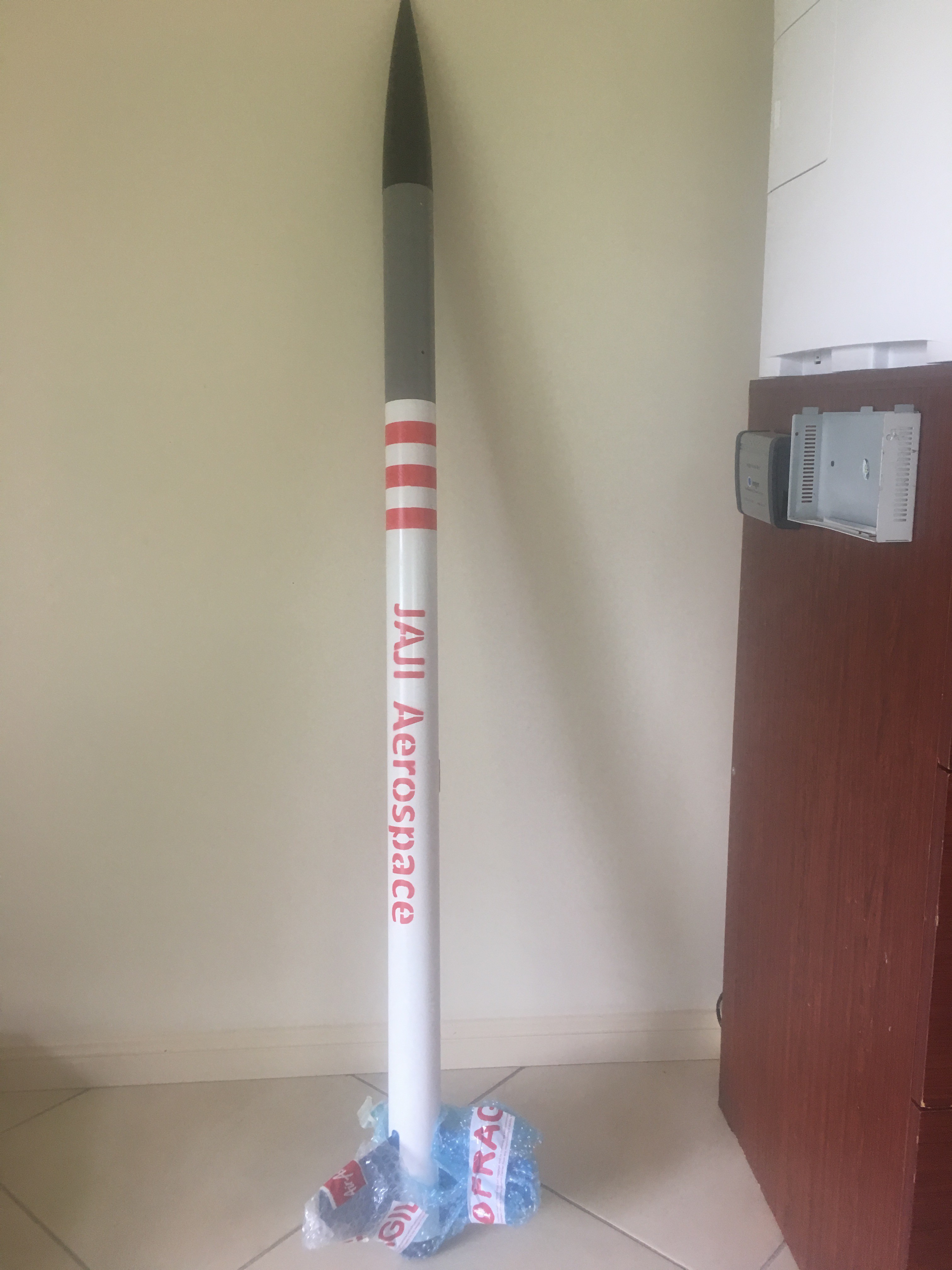
The payload airframe section (the grey section in the above picture) will be painted white. Read on to find out more about the payload and what it can do.

Payload

The launch will have an experimental payload included on it which will:-

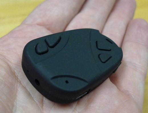
  • Capture Video of flight at 720 x 480 with sound using a 808 keychain camera
Surveillance Camera
Surveillance Camera
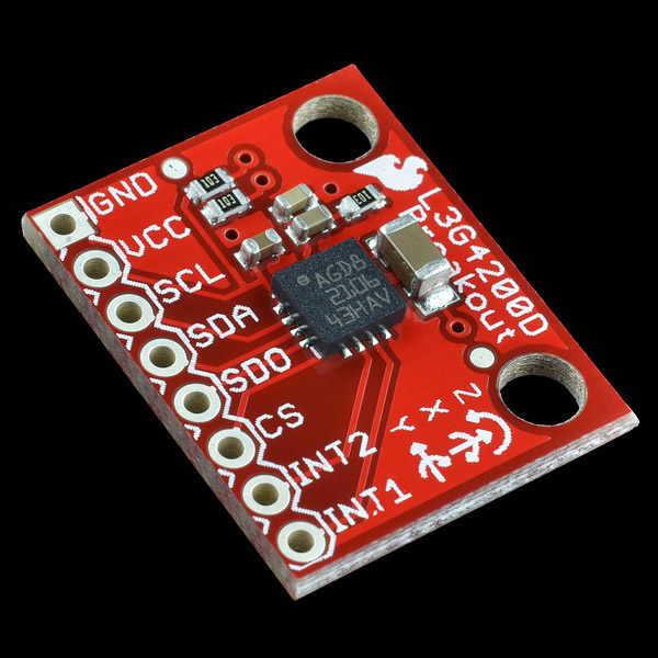
  • Capture and record gyroscope data (rotational speed) using a L3G4200D breakout board
Gyroscope sensor
Gyroscope sensor
  • Capture and record air pressure and temperature measurements using a MPL3115A2 sensor
i2c based MEMS  Air Pressure sensor
i2c based MEMS Air Pressure sensor


The final payload (before sliding into air-frame) looks like:-

Front view of payload tray

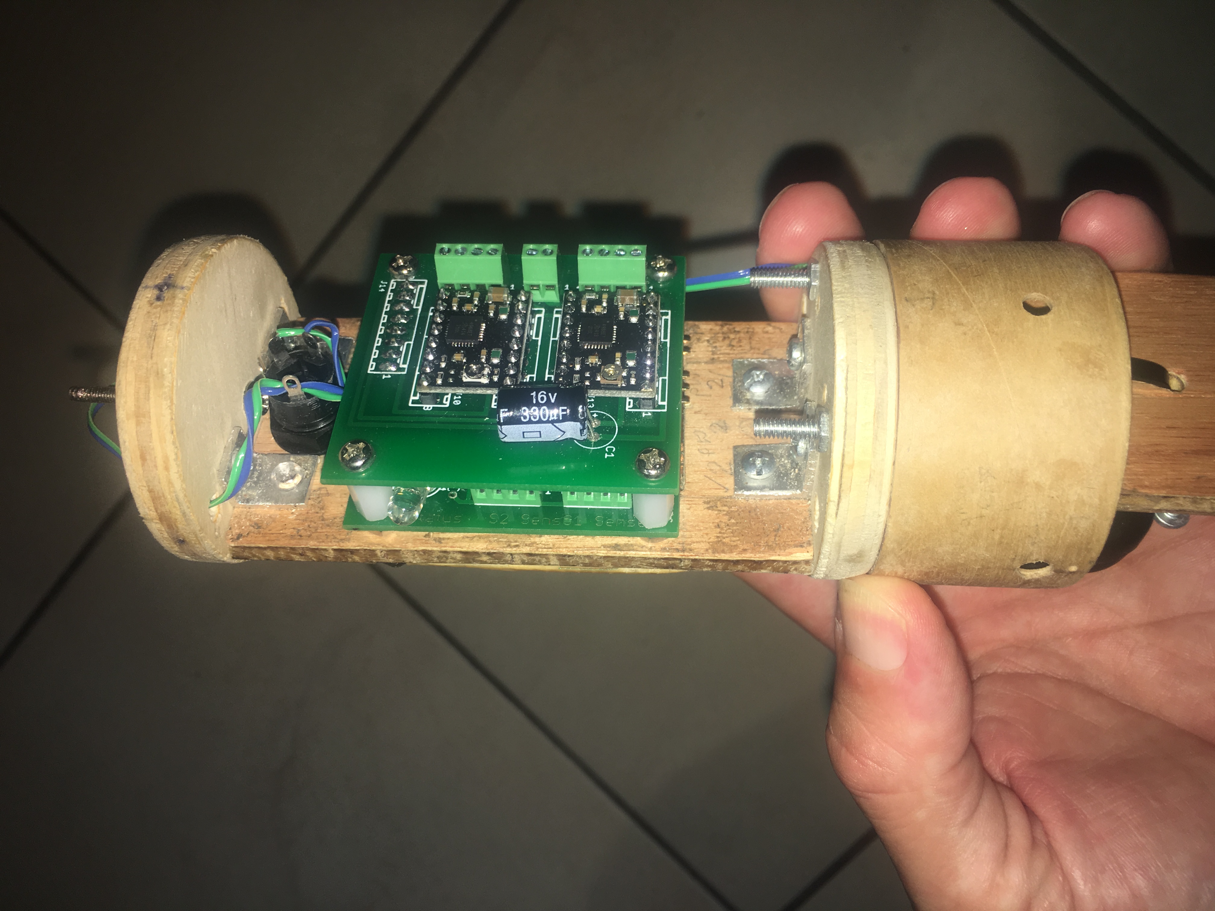
The sensors are sandwiched between the PCBs and the battery board. Space really is a premium.

Back view of payload

Notice the coin cell batter and the rotary switch on the LHS and the camera on the RHS. The rotary switch is accessible from the outside.

Payload Data

It is certainly an ambitious project, but hopefully will produce some results that will allow us to characterize the motion of the rocket as well as test our payload design and operation. The Air Pressure results will allow us to approximate the altitude of the model rocket over the flight which we will then be able to compare to our simulations. The gyroscope readings will be very interesting when we compare with video recorded motion of the rocket. Temperature will be interesting, but is of less importance.

I’ve created a video that allows us to compare the ‘real world motion’ of the payload when compared with the motion depicted using the gyroscope data. See below.


The Rocket Motor

We will be utilising a G76-10G Aerotech engine. This translates to an average thrust of 76 Newtons over the total burn time of approximately  Below is a plot from OpenRocket.


Simulation of launch

As you can see, this rocket will achieve an altitude just shy of 300 metres. (less then 1000 feet). This is well short of the 4000 feet ceiling we have at our launch site. We still expect the launch to be spectacular.

Remaining Preparations

Remaining preparations include:-

  • Generating Launch simulation to ascertain key information like ejection delay, speed of rocket off the launch rail
  • Confirming CG and CP points (checking stability of the rocket)
  • Confirming launch location suitability and timing
  • Checking and testing launch Electronics systems
  • Charging batteries
  • Performing inventory check and packing boxes with required items
  • Writing and testing procedures
  • Double checking motor risks (issues that other people have recognised with the motor). The AusRocketry forums were helpful in this respect.


Air Pressure and Temperature Sensor

It was decided on a whim to purchase and install a Air Pressure + Temperature sensor for the next flight. I purchased a :-

http://core-electronics.com.au/search/?q=MPL3115A2

I picked this because the pins were arrange in same order as the Gyroscope pins. So I had a relatively easy job of just soldering this on top of the Gyroscope.

Programming wasn’t as simple. The libraries that you can get from AdaFruit or SparkFun generally are one-shot, in that you need to wait a significant time for the sensor to return a value (in the order of a second). This is not satisfactory because we need to capture as much gyroscope data as possible. So we looked into a demo Arduino program by Sparkfun called SparkFunMPL3115A2AdvancedExample.ino. In this example it would get the sensor to collect data autonomously and at the end it would fetch all the data. It utilises a FIFO that can store up to 32 measurements of air pressure/temperature. We programmed our sensor to collect data every second. We allowed sufficient time at the end of the~8 seconds of gyroscope collected data (FRAM memory only has enough space for ~8 seconds of data) to get another 24 data points, by employing a 24 second delay. This should allow us to get 32 seconds (~ 3/4 flight profile) of air pressure and temperature. The program then stores this data at the very end of the FRAM.

We then modified the dumpFRAM routine to process the air pressure/temperature data to allow us to see what was recorded!

I tested this out by running up the hill with the sensor. Sure enough, the air pressure reduced as I ran up the hill. This extra sensor is a great addition to the flight. It will allow us to approximate the flight altitude over time, allowing us to compare it with the predicted flight altitude over time (generated from Open Rocket).

Below is an extra from a dump from the routine dumpFRAM.

2 151 79 32
RS: 0.02, -1.14, 0.01
2 151 115 216
RS: 0.03, -1.25, 0.07
2 151 152 144
RS: 0.02, -1.22, 0.02
2 151 189 72
RS: 0.04, -1.26, 0.11
2 151 226 0
, Temperature = ,26.7, C, Pressure = ,101.41, kPa

Here RS means Rotational Speed

The other lines with 4 numbers can be combined to produce the time in microseconds

At the end is the Temperature and Pressure. These are ~1 second apart.