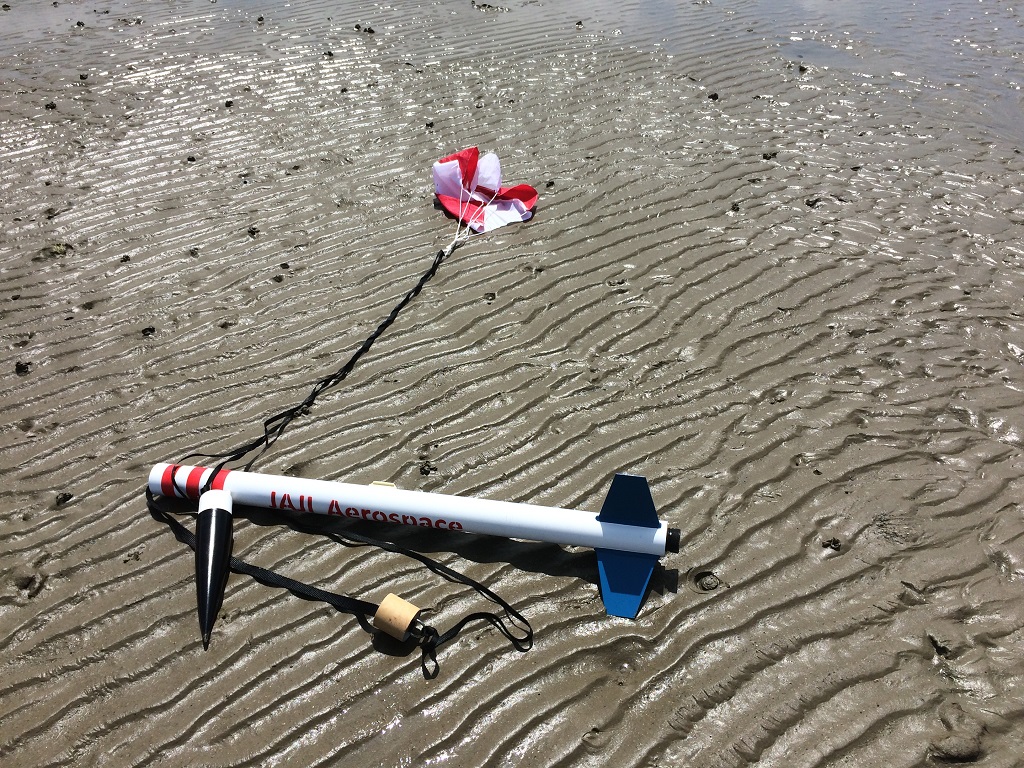
I decided to create a radio tracker for this rocket as I expect that it to travel quite far and high when it has the “real” large motors installed in it.
The Parts List
- Arduino Pro Mini – 5 volt version
- RFD900u modem
- AdaFruit Ultimate GPS
- 3 Amp/5 volt UBEC
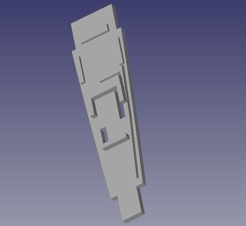
- 3-D printed “tray” to fit into the nose cone
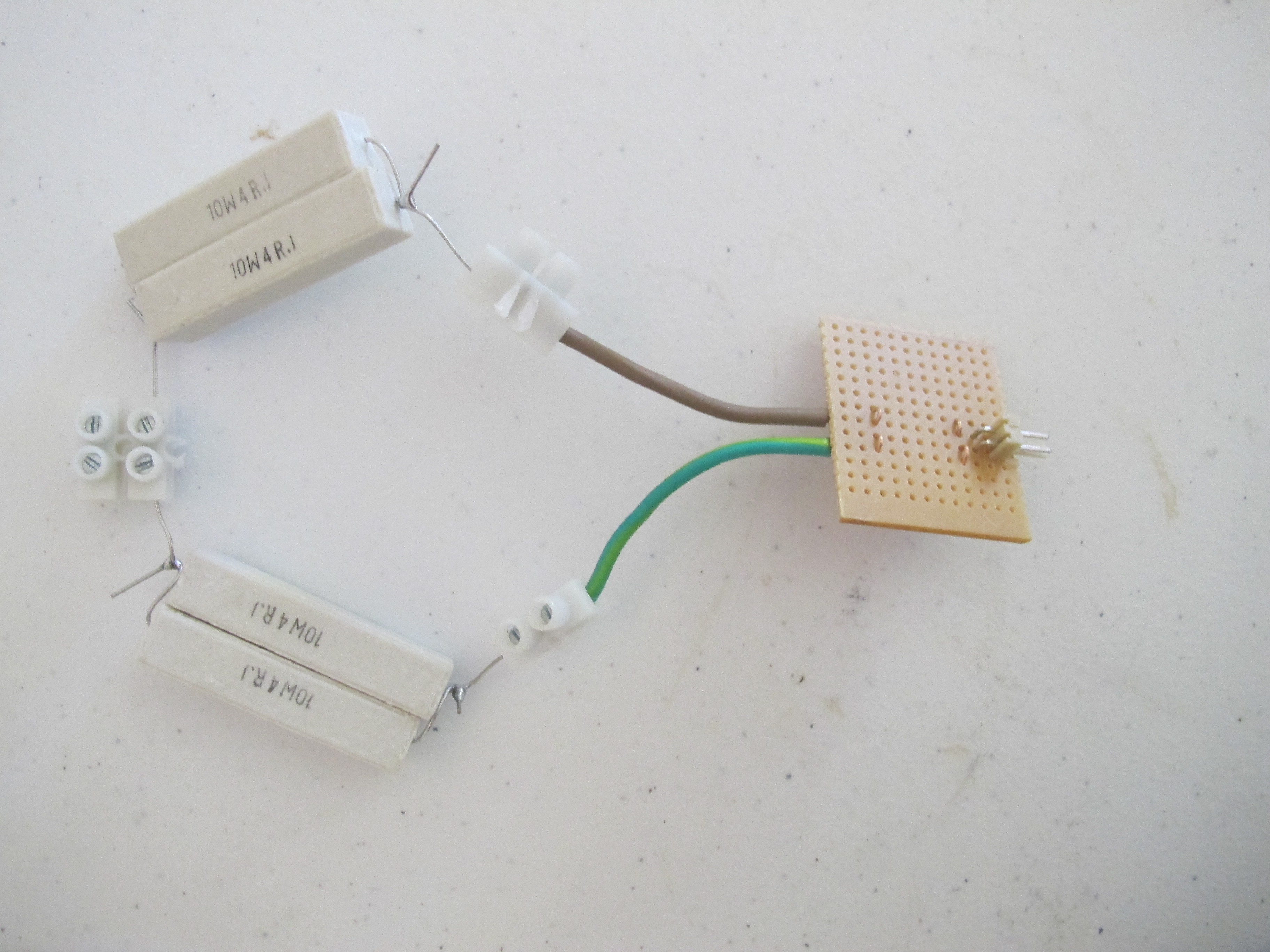
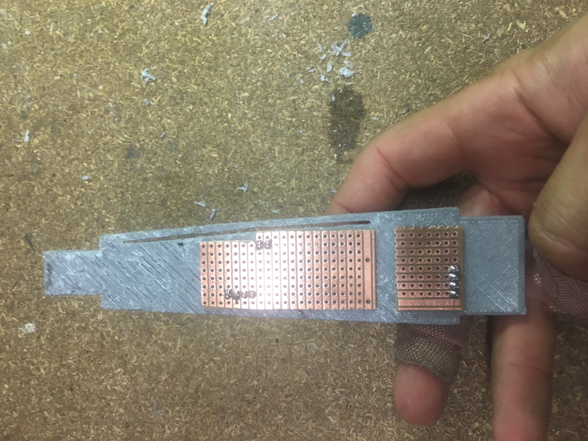
- Veraboard + header pins + wire
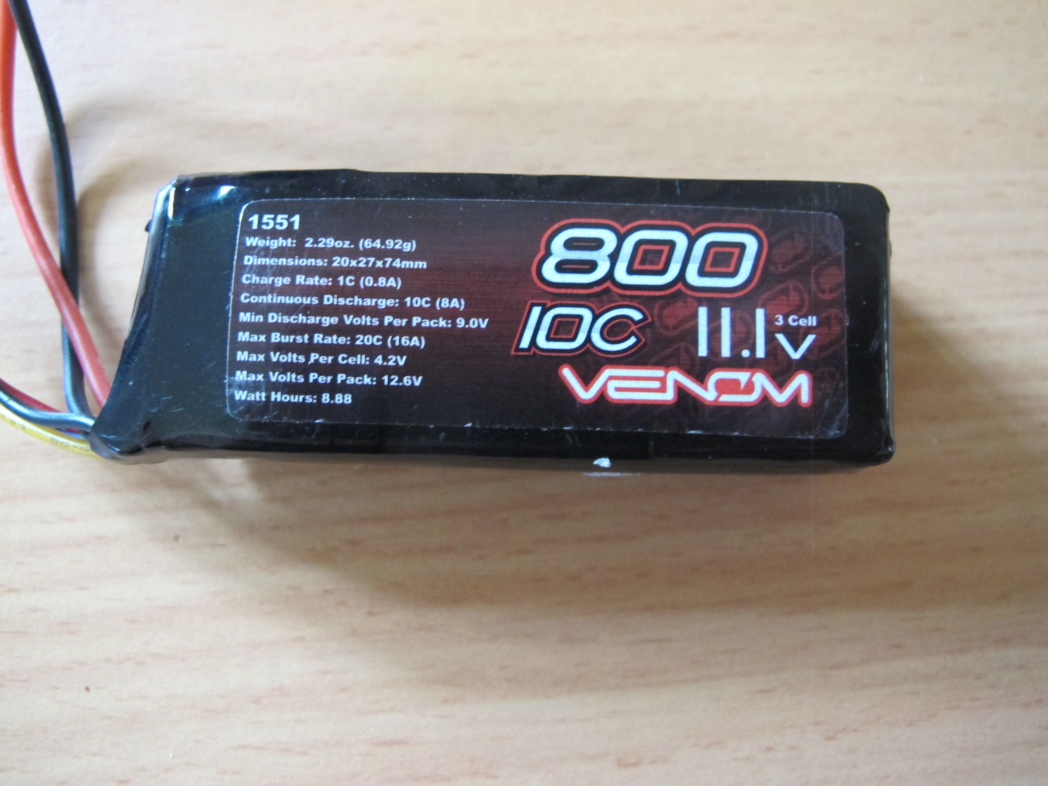
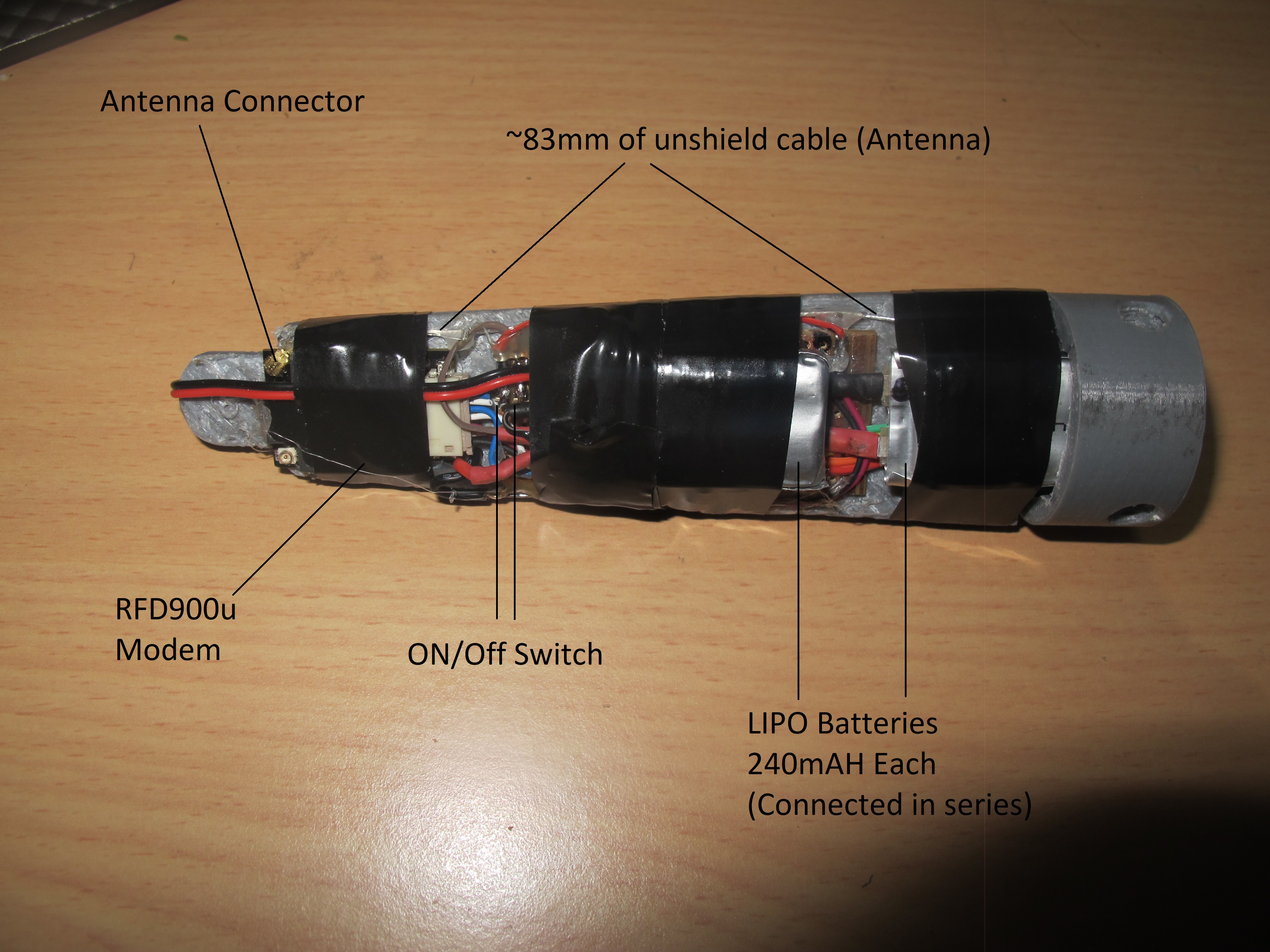
- 2 x 240mA LIPO batteries
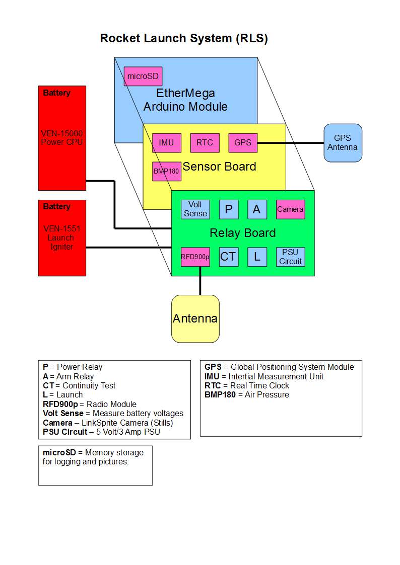
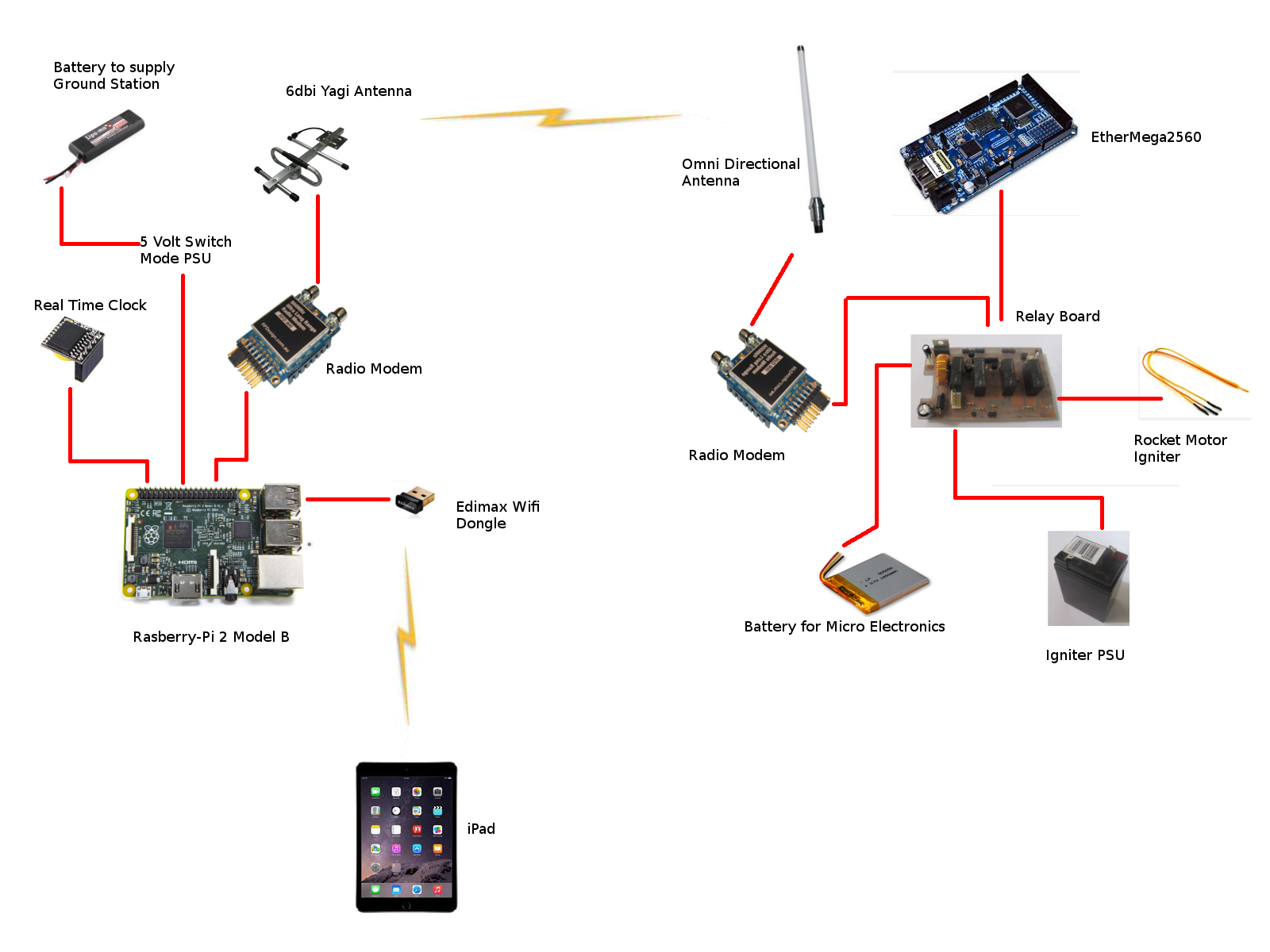
The Design
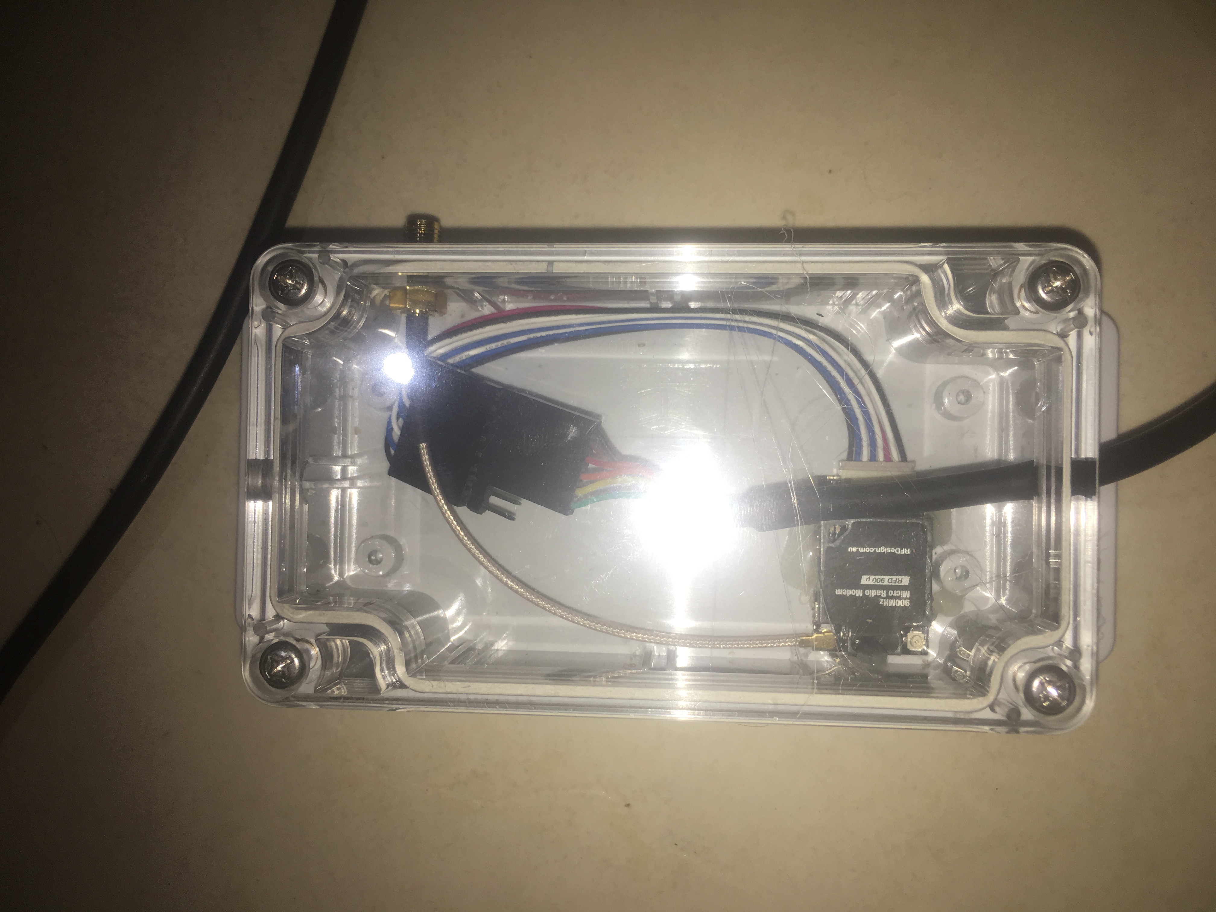
The RFD900u modem
I connect the RFD900U modem on the rocket end to the Arduino – pins 4,5 and use Software Serial. I power the modem directly off the 5 volts from the UBEC as the power requirements of the RFD900u modem can exceed the maximum current the Arduino can supply.
I’ve loaded the modem with latest version of firmware 1.13 and after setting to the default settings I changed:-
- ECC to on
- TXPower to 17
I set the TXPower to 17 because life of the batteries is a big factor and 20 will suck the batteries dry. Tests have shown that every minute of operation, the batteries drop by 0.01 volts. So if the starting voltage is 8.30 volts and the final finish voltage is 7.5 volts, then we are looking at about 80 mins of operation. This is fine.
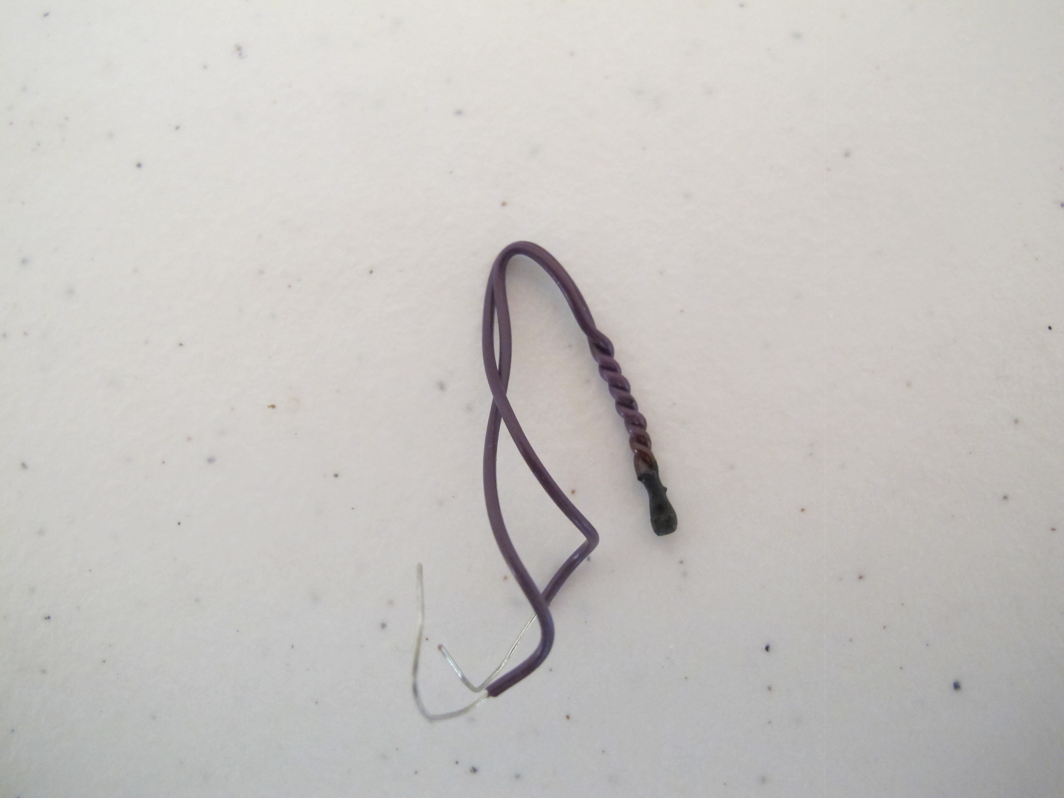
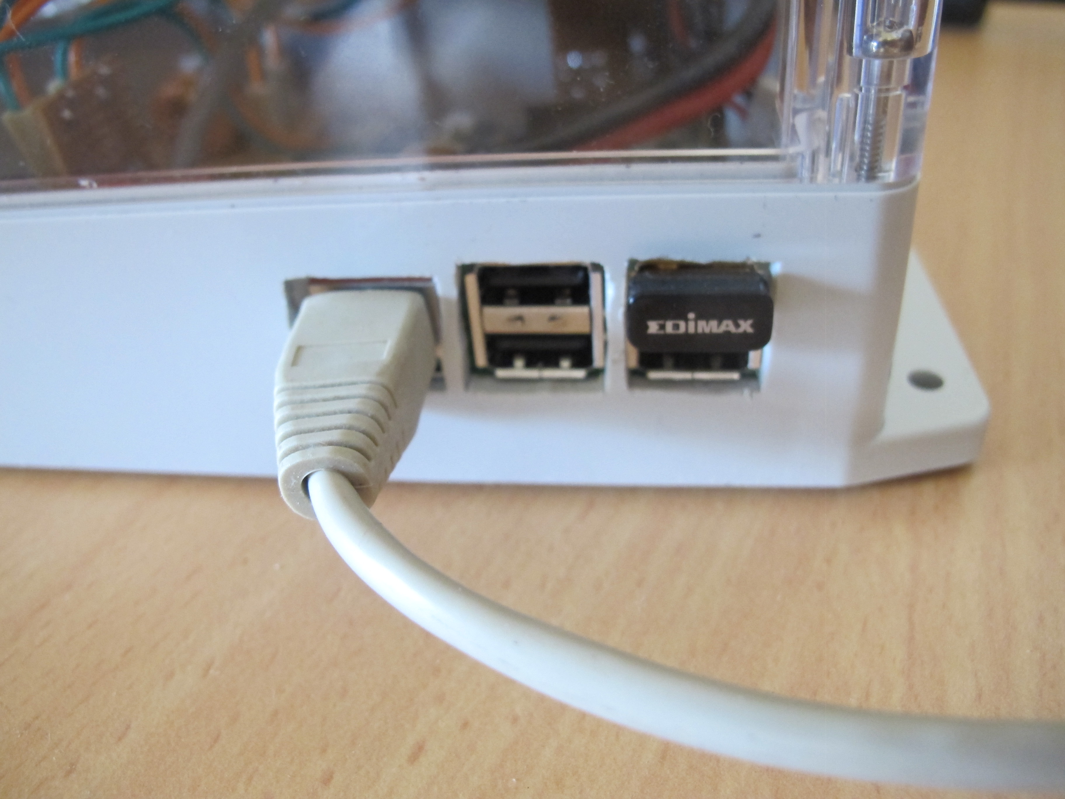
One of the issues I had was working out the antenna side of things. There is just not enough space to cram a 1/2 dipole antenna. So I have to go for a 1/4 dipole antenna. unfortunately, there really isn’t enough space for this either!! So I converted a cable for connecting an antenna INTO the antenna!
The Ultimate GPS
This device is connected to pins 2, 3. It chews about 20mA of power and is also powered directly from UBEC.
I’ve written the Arduino program to log GPS points to the internal logging area. Unfortunately, it only logs it every 15 seconds. That will have to do.
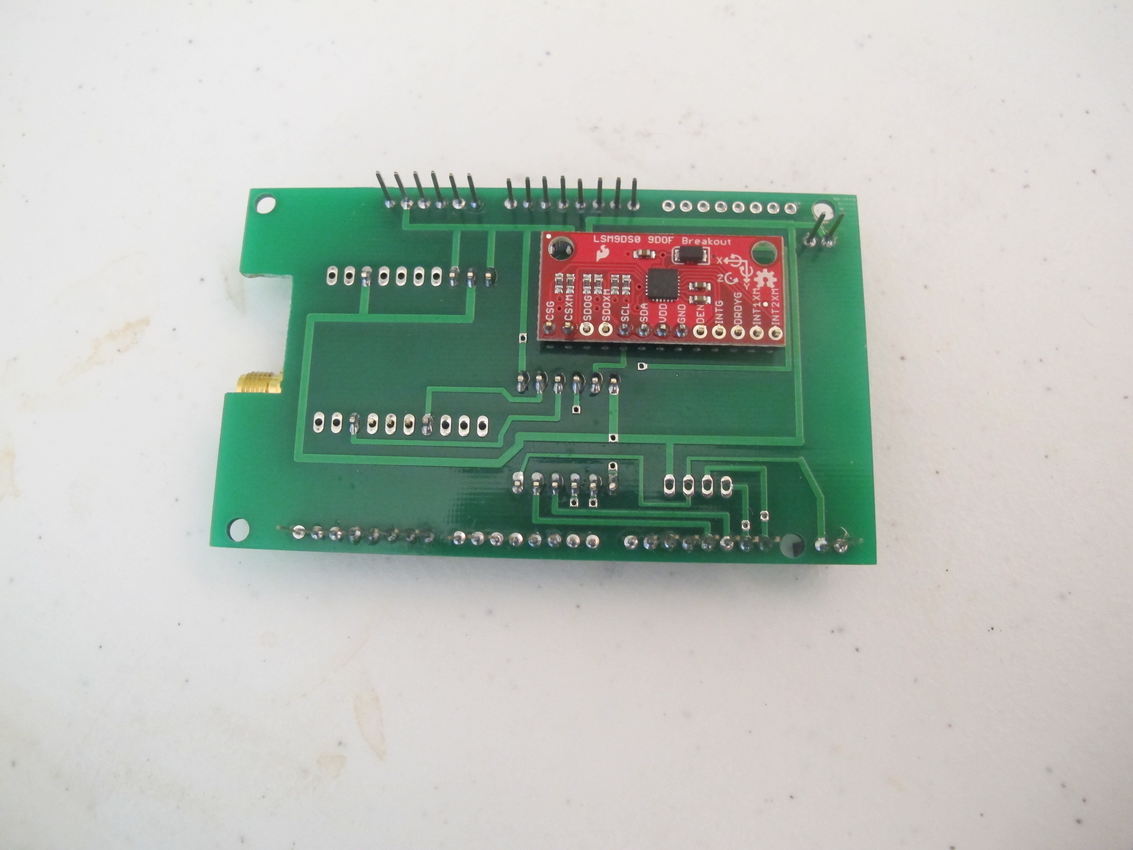
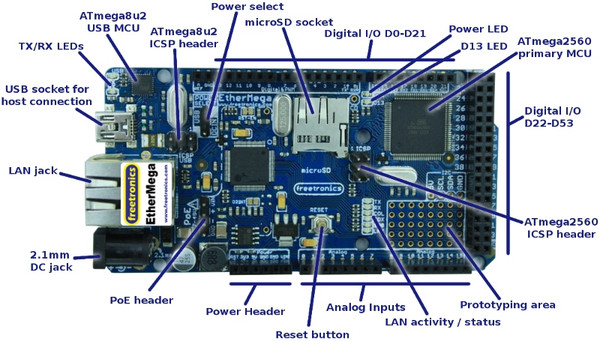
The Arduino Controller
There isn’t much to this. I choose to use a 5-volt version because all devices I’m connecting to it can operate at 5 volts. This controller doesn’t have much work to do. All it needs to do is read GPS data and send it to the Receiver via the RFD900u.
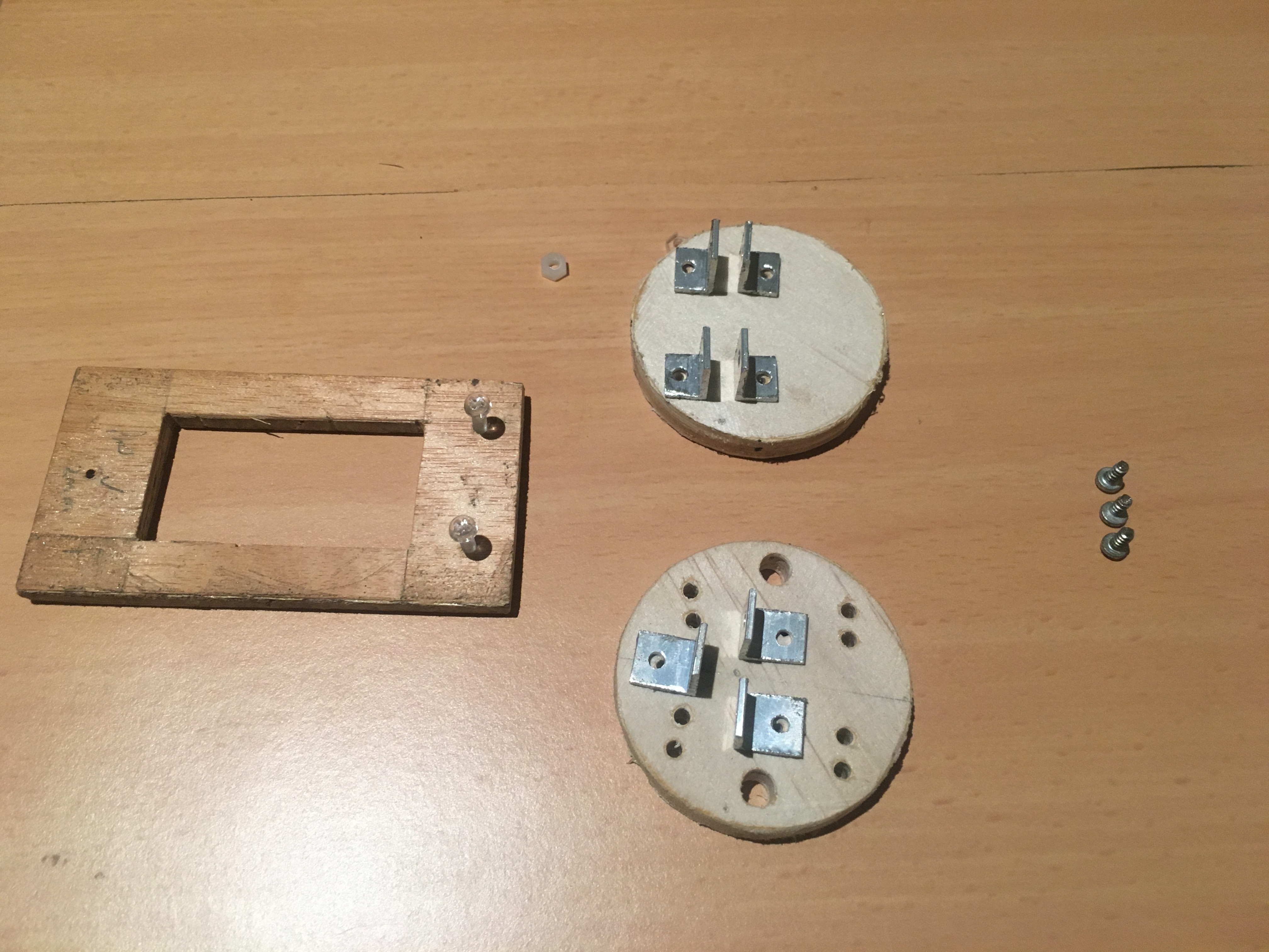
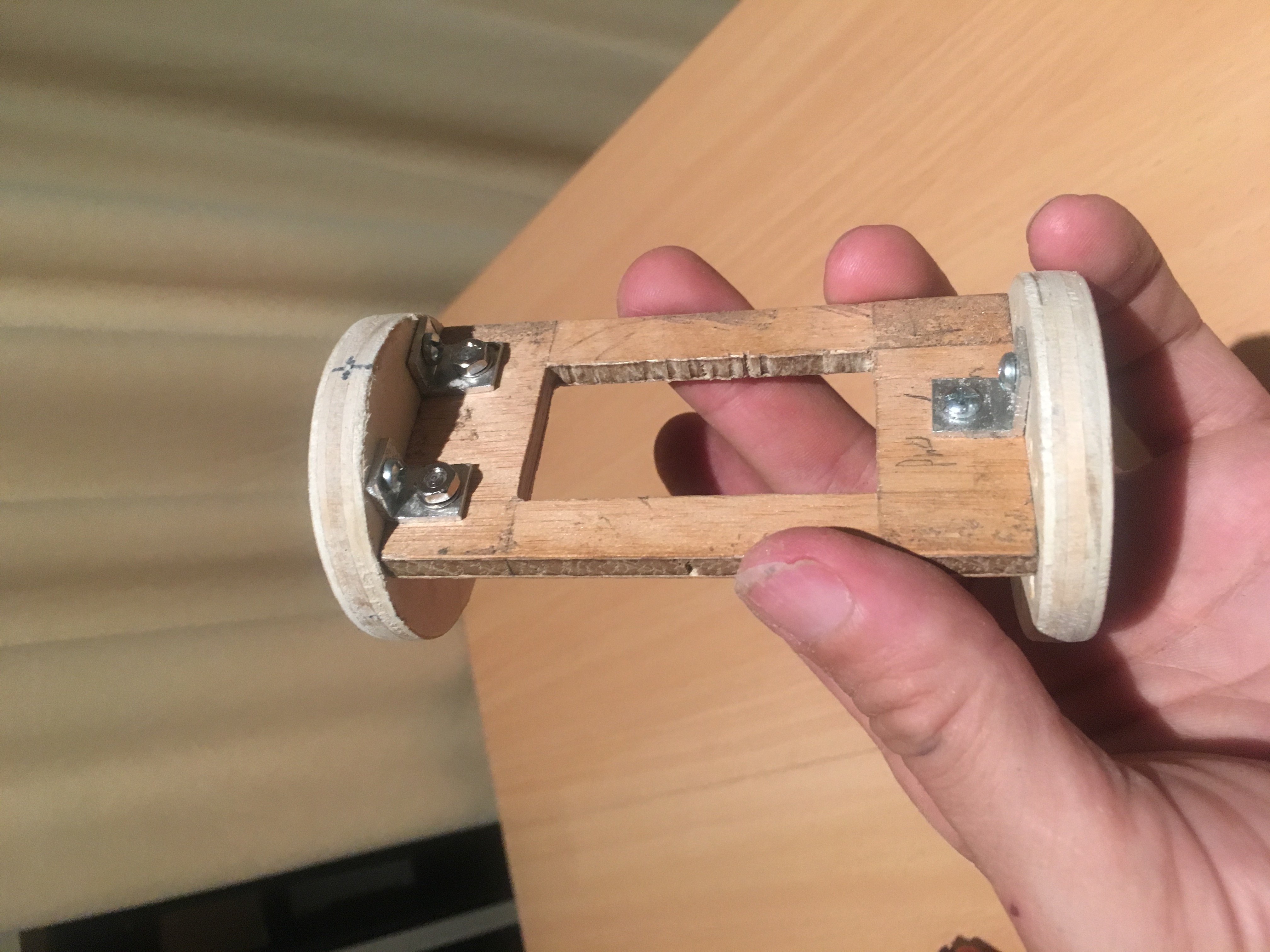
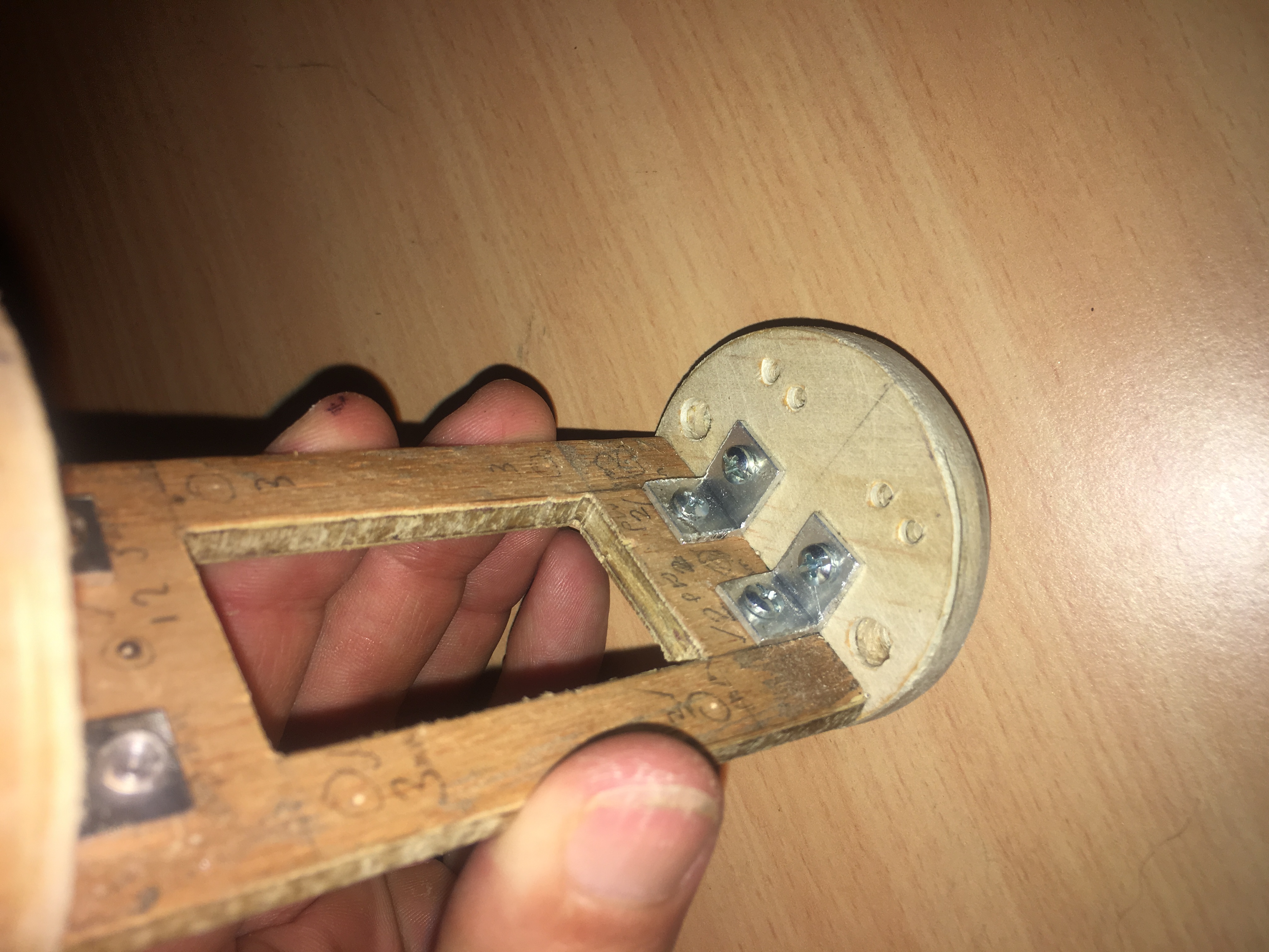
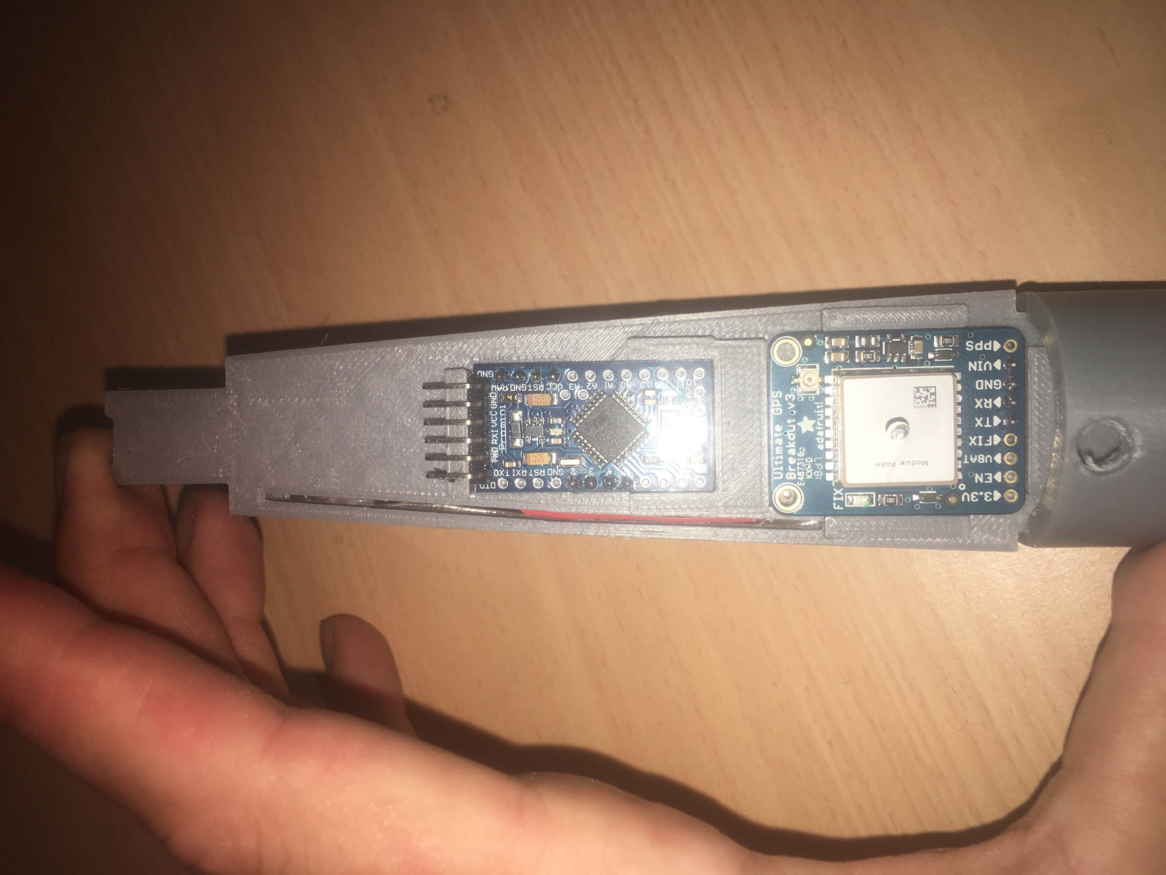
The mounting tray
I wanted to mount this inside the fibre-glass nose cone. This was quite tricky because of the limited space. One thing I wanted was for the tray to follow the contours of the inside of the nose cone. i.e. rub up against it. This will provide some stability in flight. It will also maximise area for mounting the components.
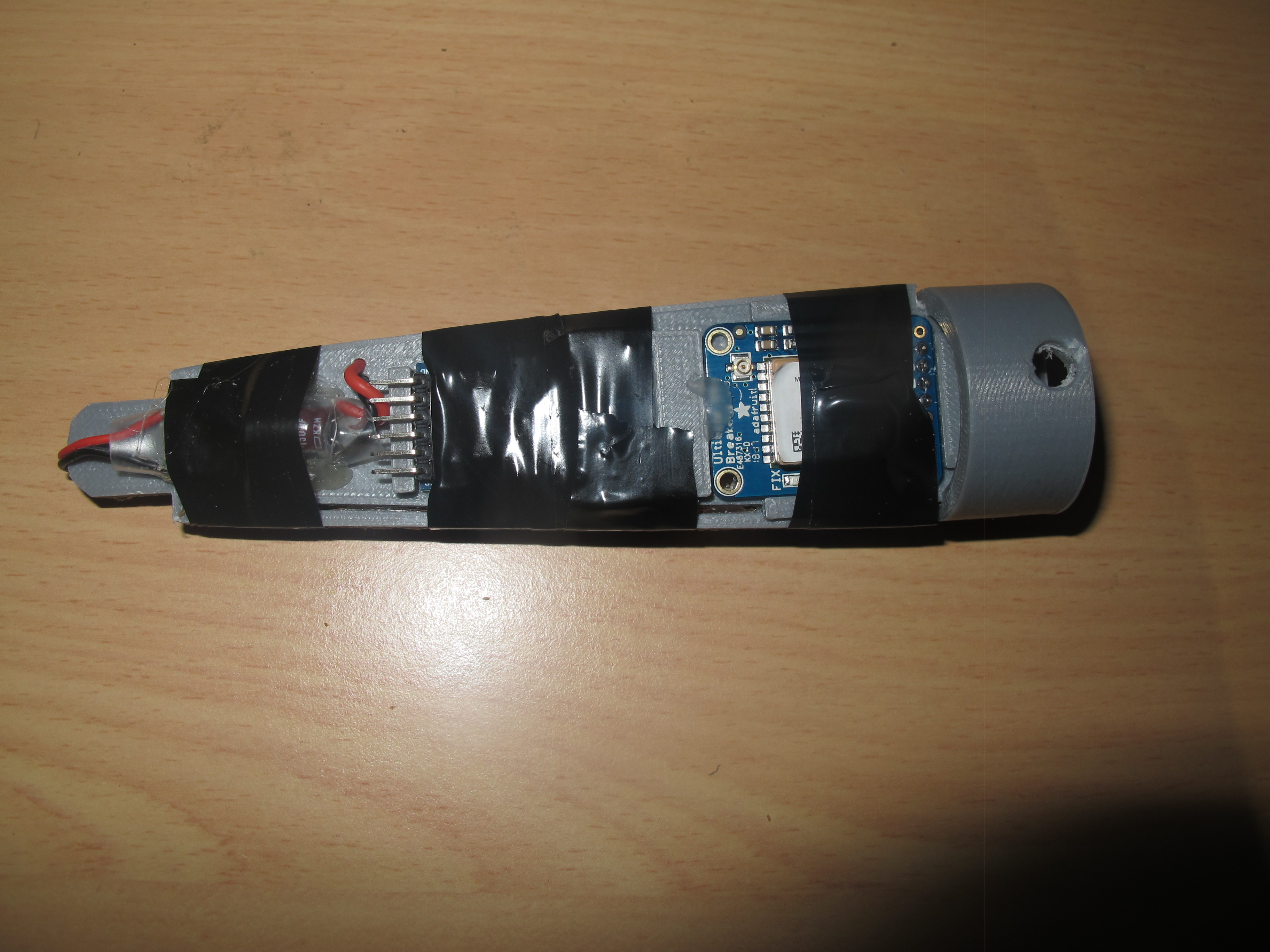
Construction
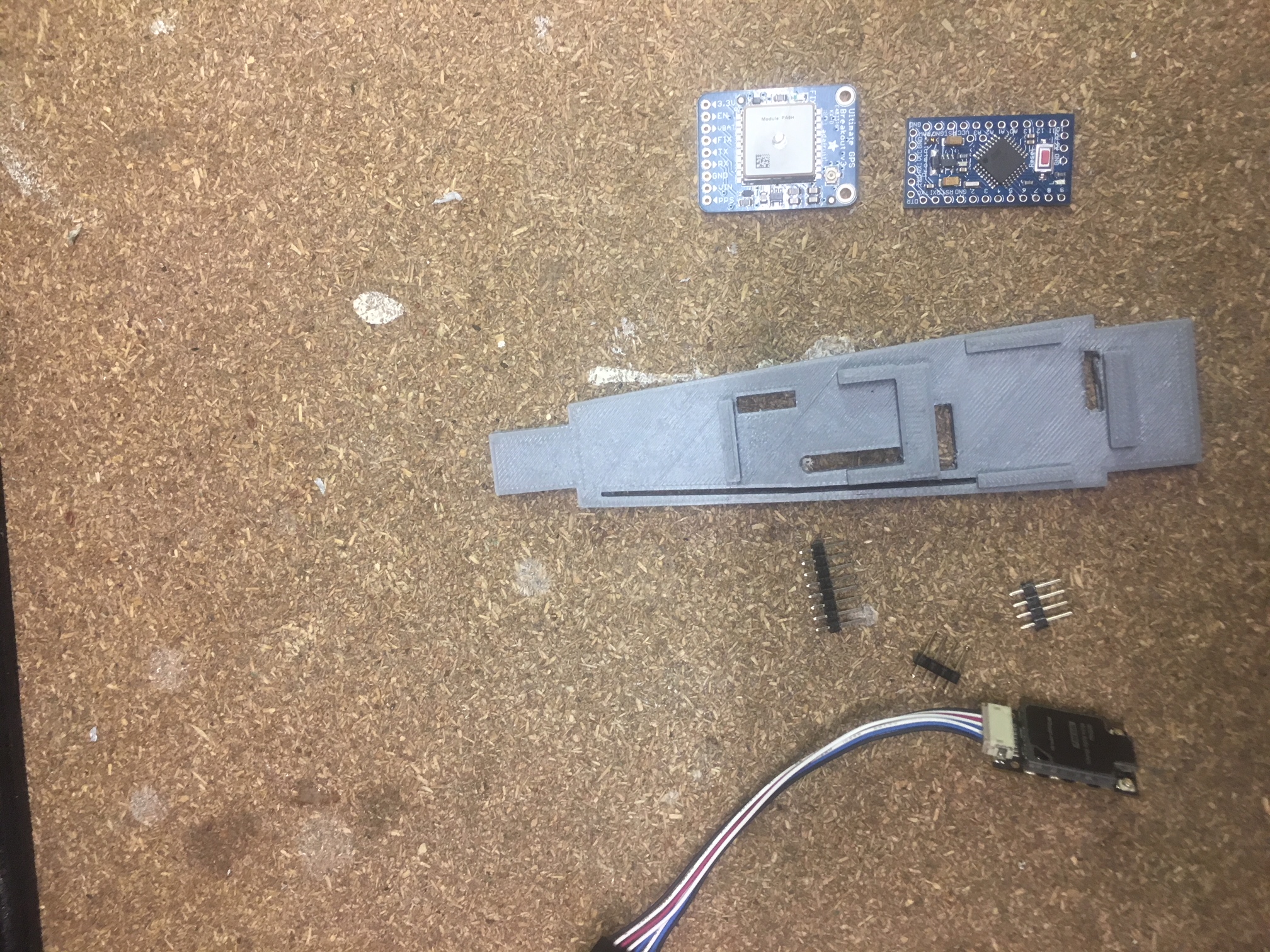
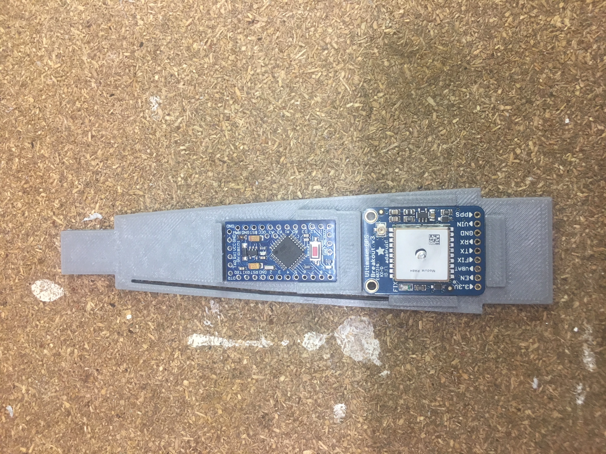
Here are some photos:-
I dislike Hot-Glue, but It came in handy for attaching:-
- RFD900U modem
- 2 x LIPO batteries
- Keeping wires “safe”
- Ensuring GPS and Arduino module can’t pop out.
People at AusRocketry forum recommended some tape to ensure that the modem doesn’t rattle off. This sounds like a wise idea.
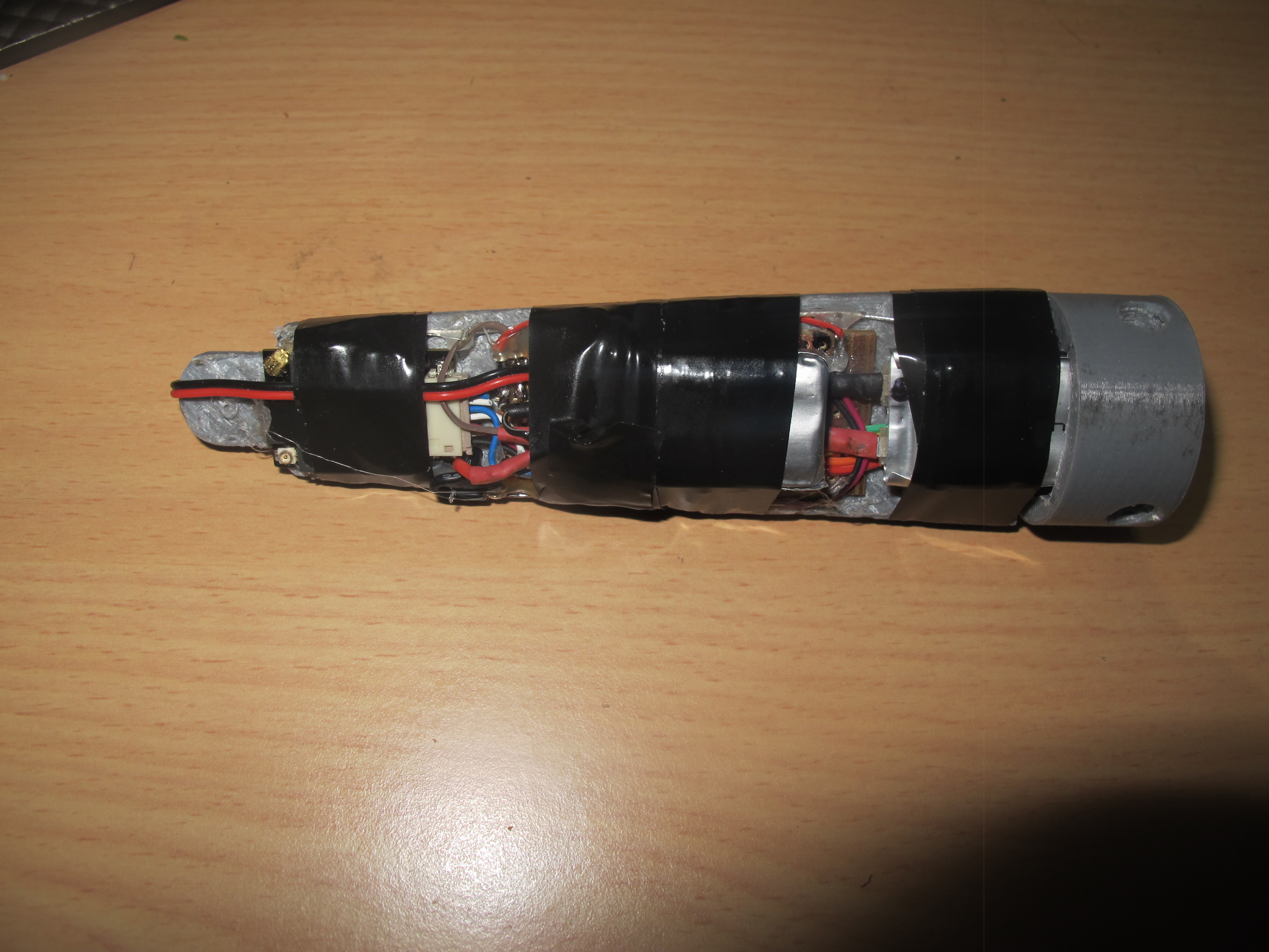
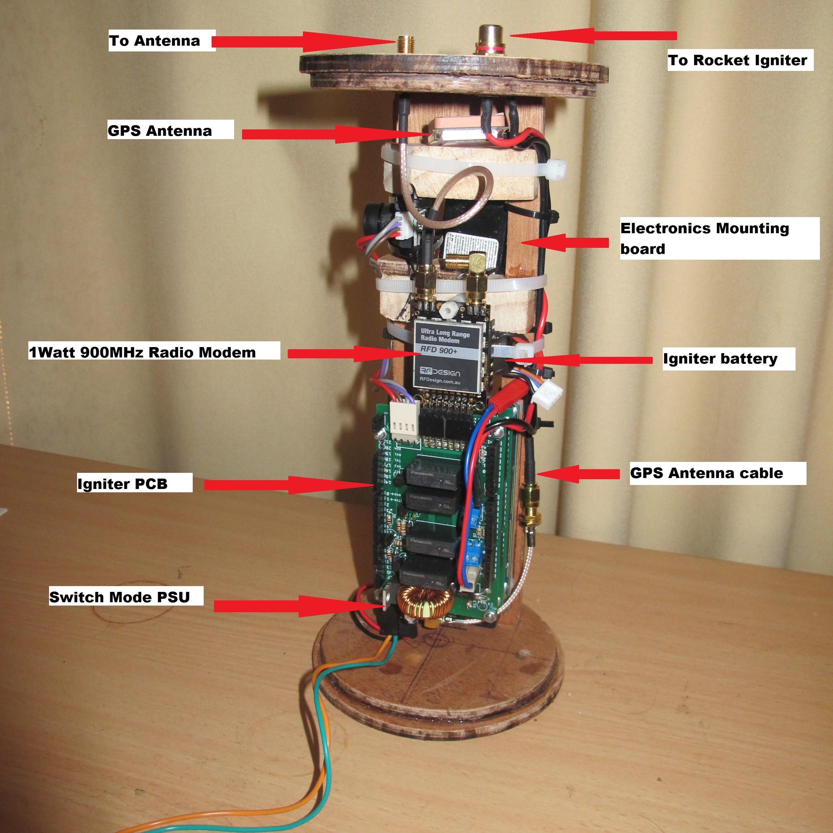
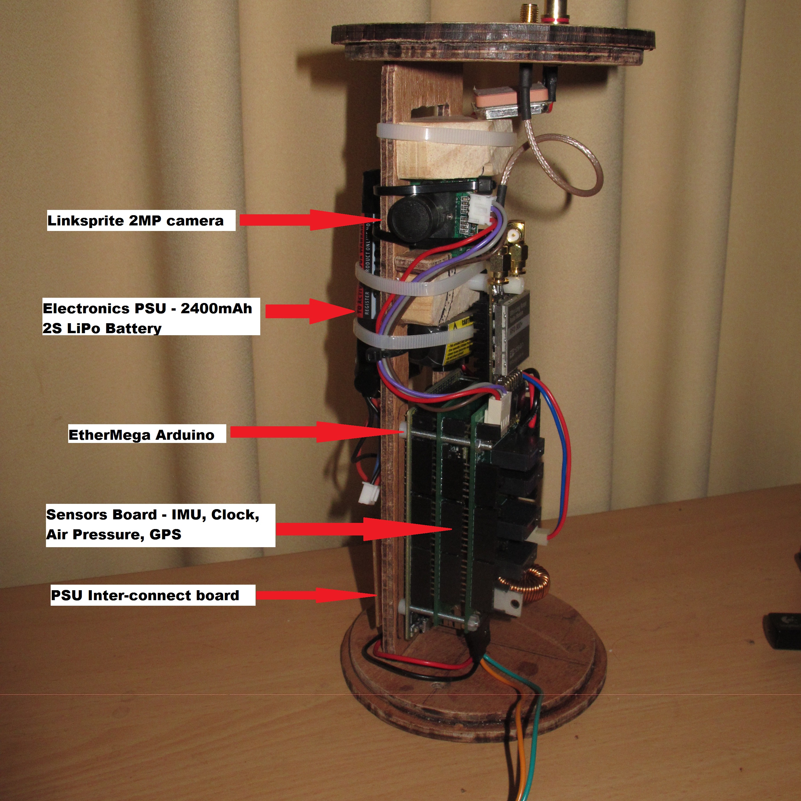
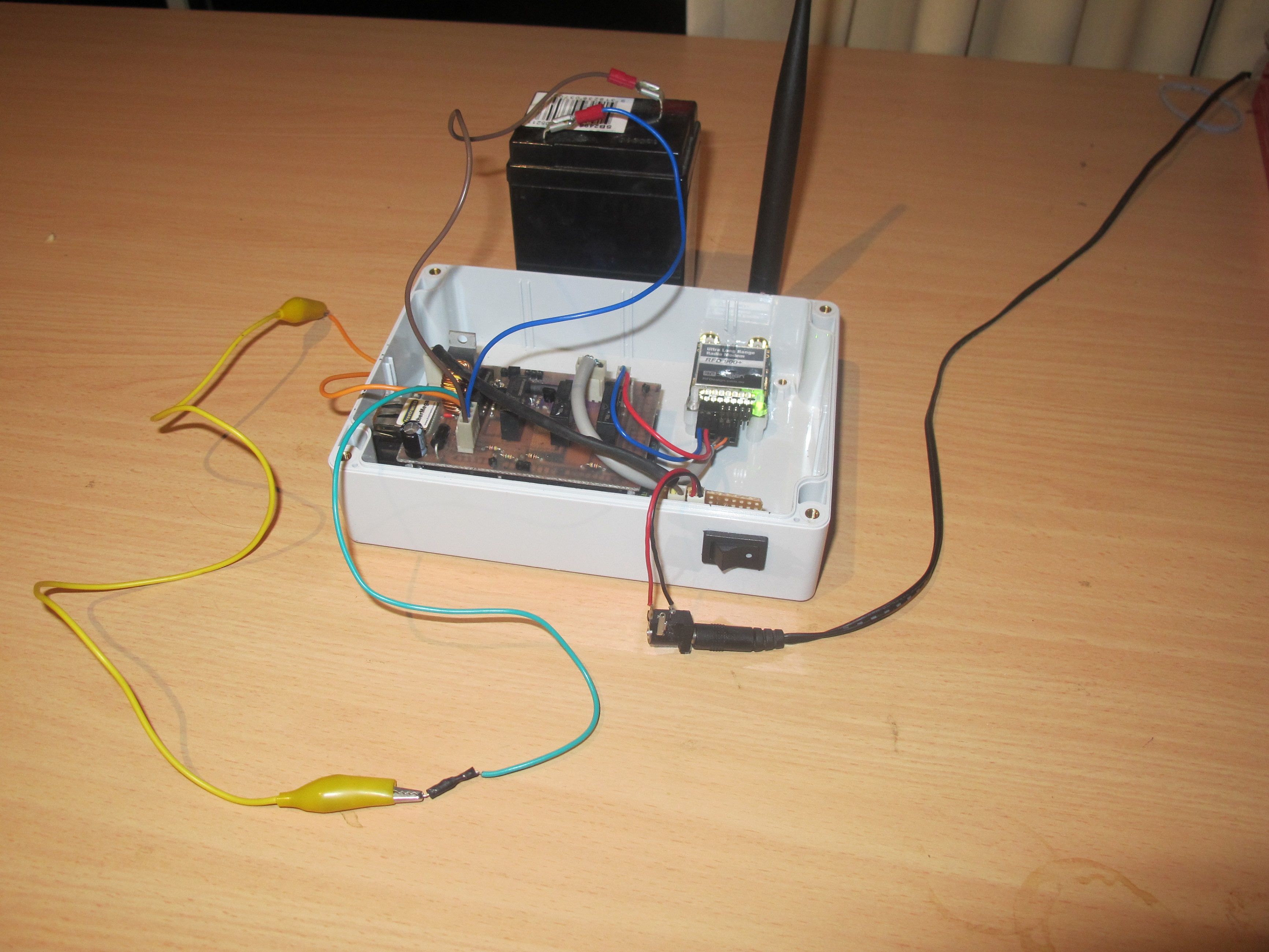
See the photo below showing the various parts of the tracker.
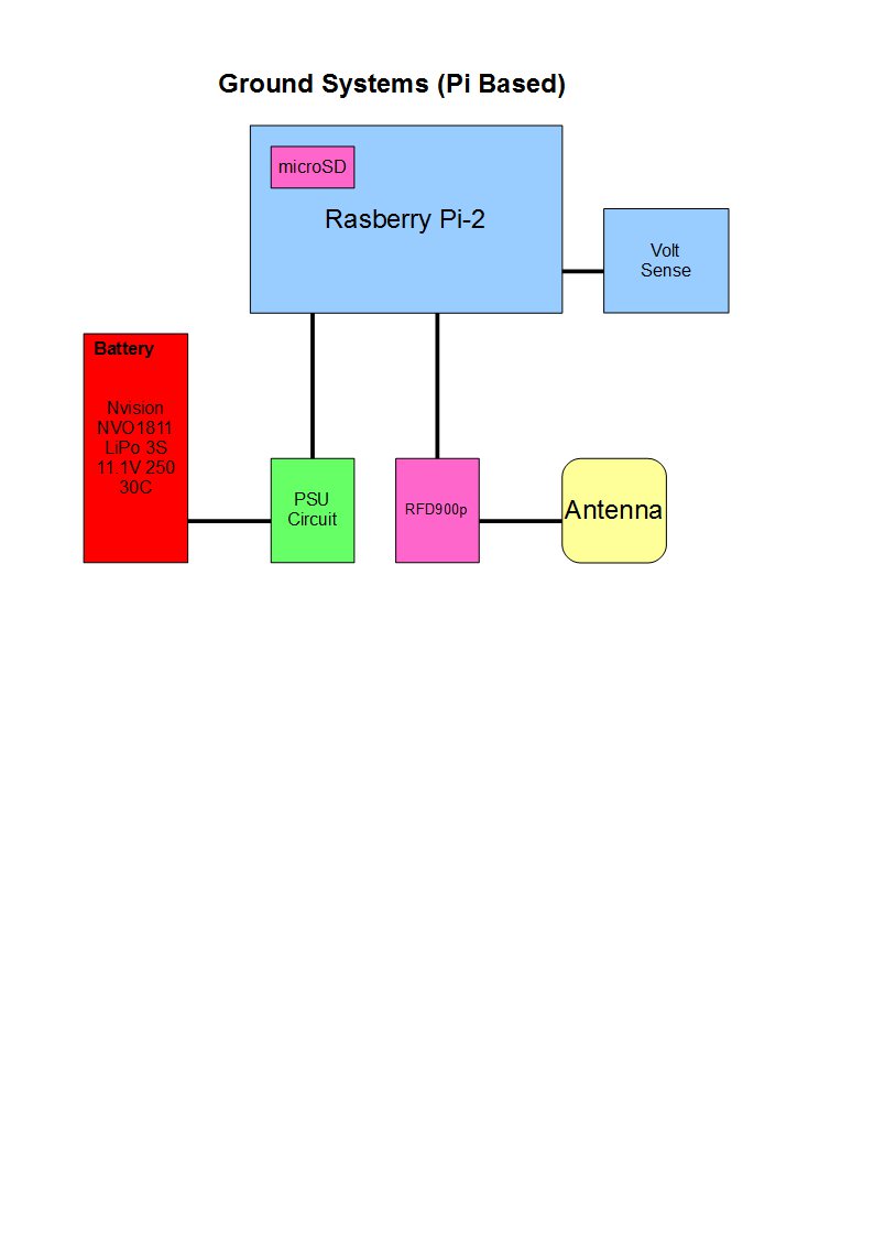
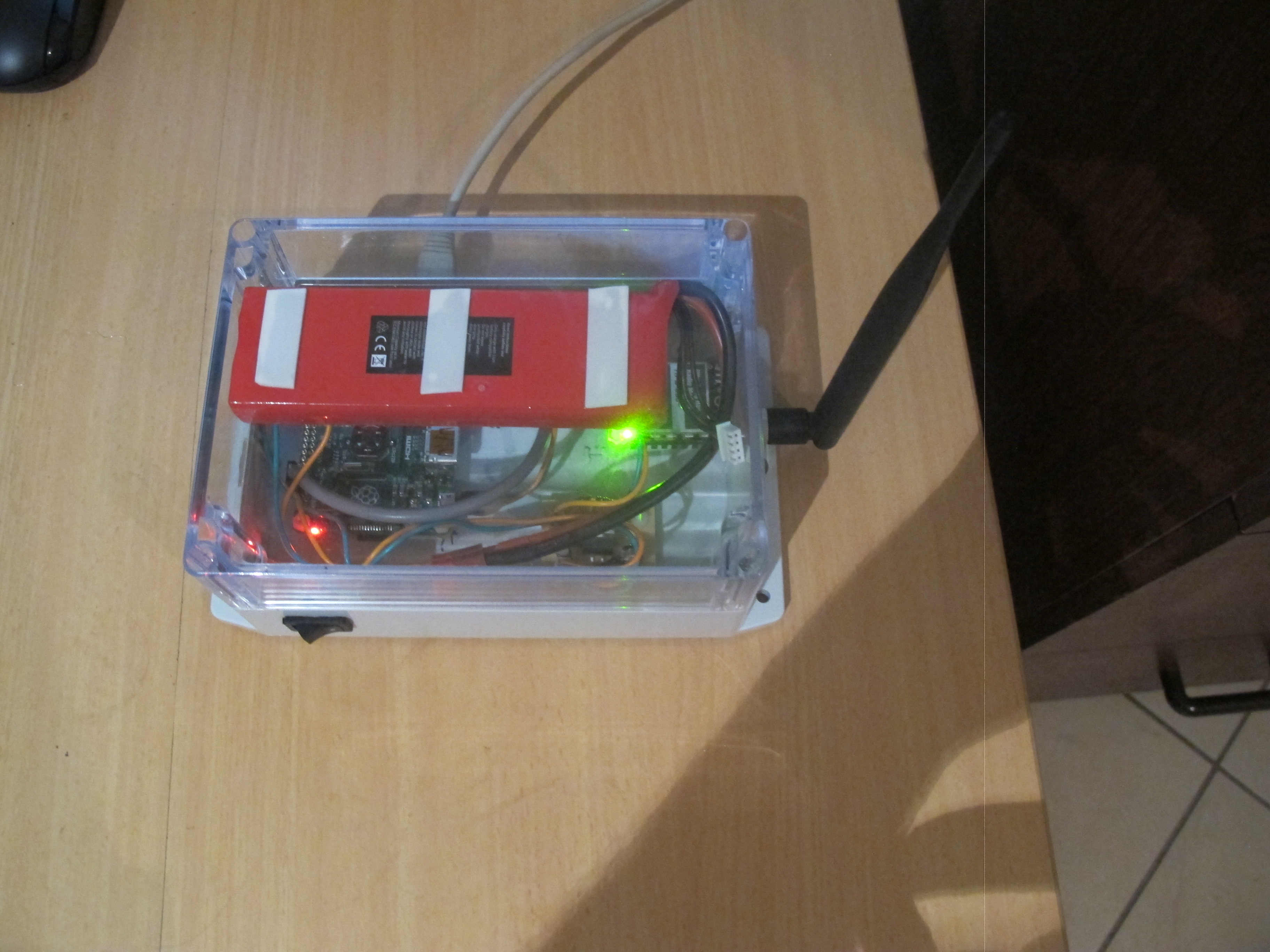
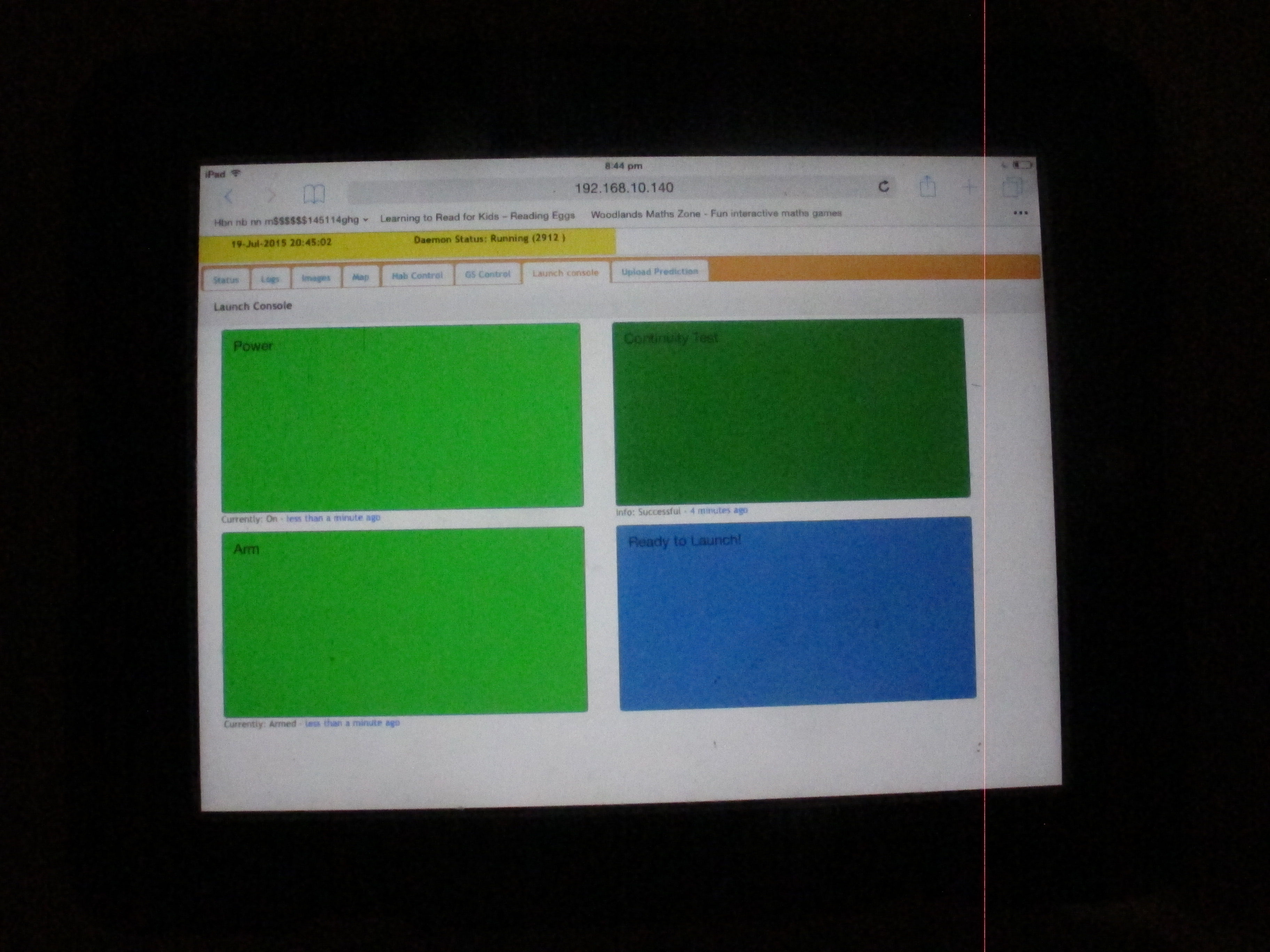
The Ground Station
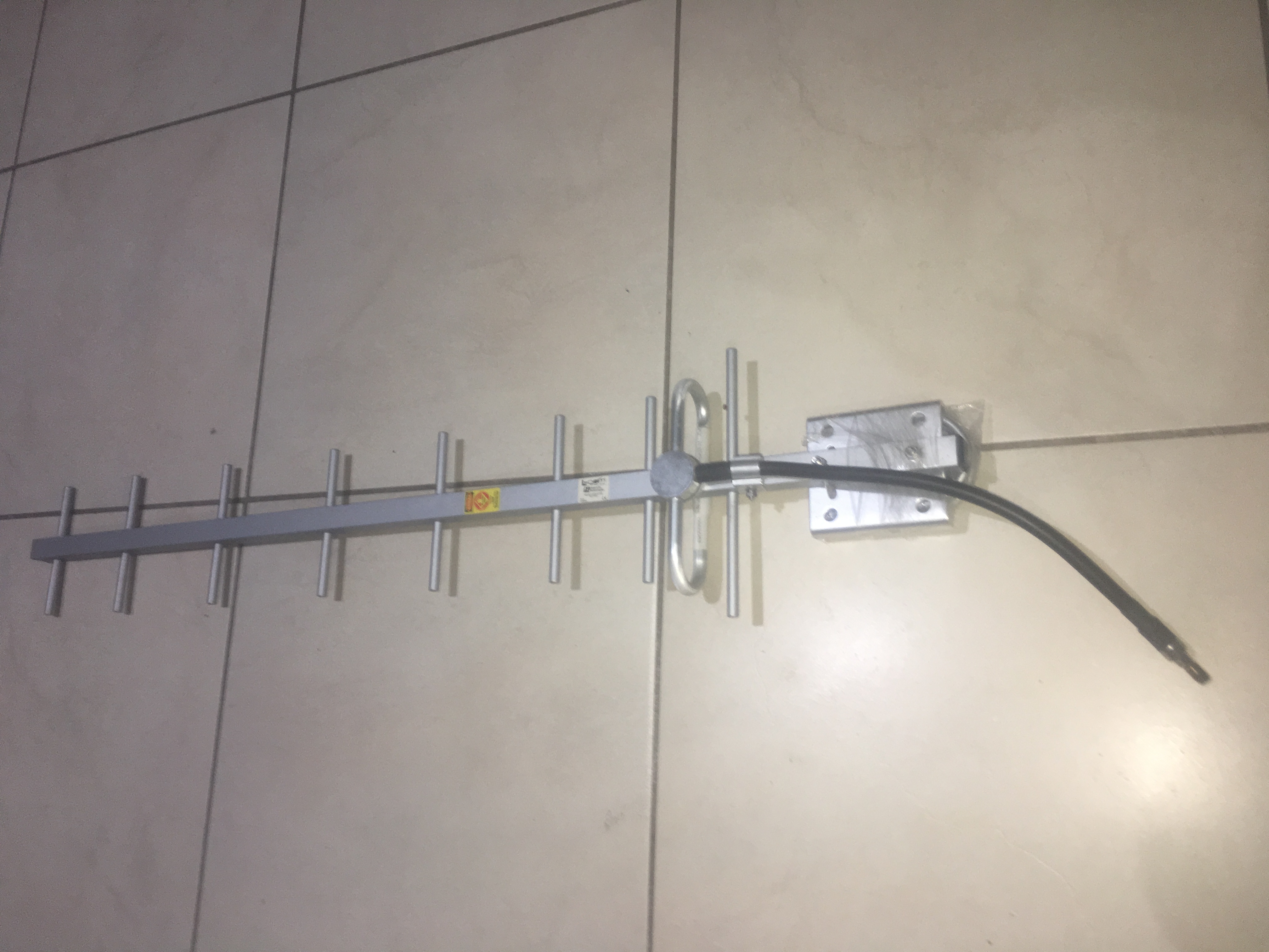
Range Testing
I reduced the power on both modems from TxPower = 20 to TxPower = 5. Then I did some tests about 100metres away. I still got RSSI of about 120, which isn’t too bad, considering it is low power.
I estimate it should be able to do about 2km no problems with this configuration; with optimal environment i.e. LOS and plenty of clearance. Probably able to get a few more km in ideal circumstances.