Category Archives: L1 Certification

Our Model Rocket launches At QRS in January

This post is a little late, but still worth getting out.

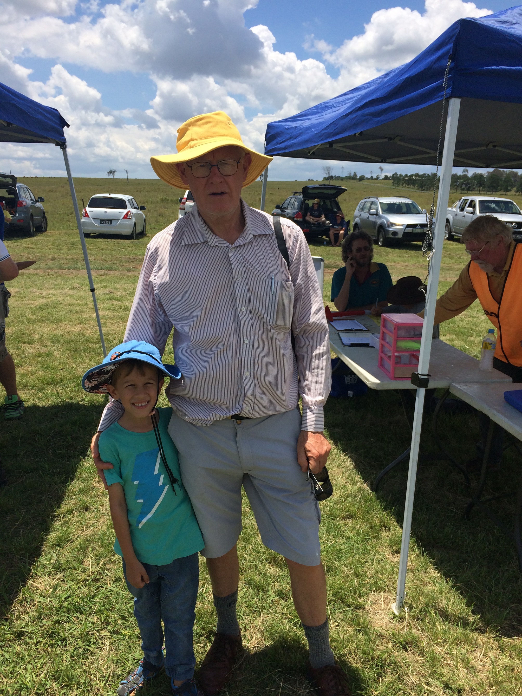
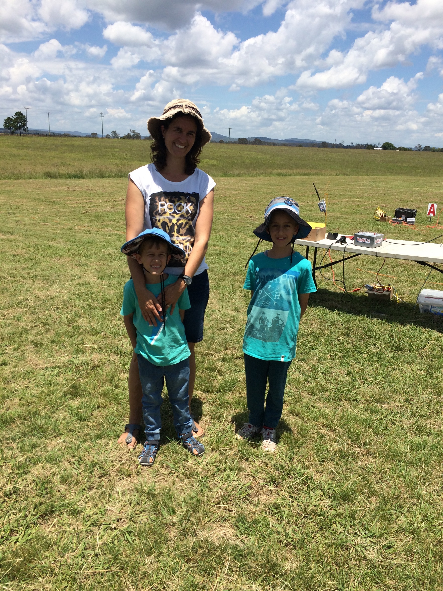
On the 10th of January 2016, myself, Anna, Jeremy, Isaac and “Grandpa Val” travelled to the Goldcoast to attend a Queensland Rocketry Society Launch day. We all got to fly a rocket! Even Anna did!
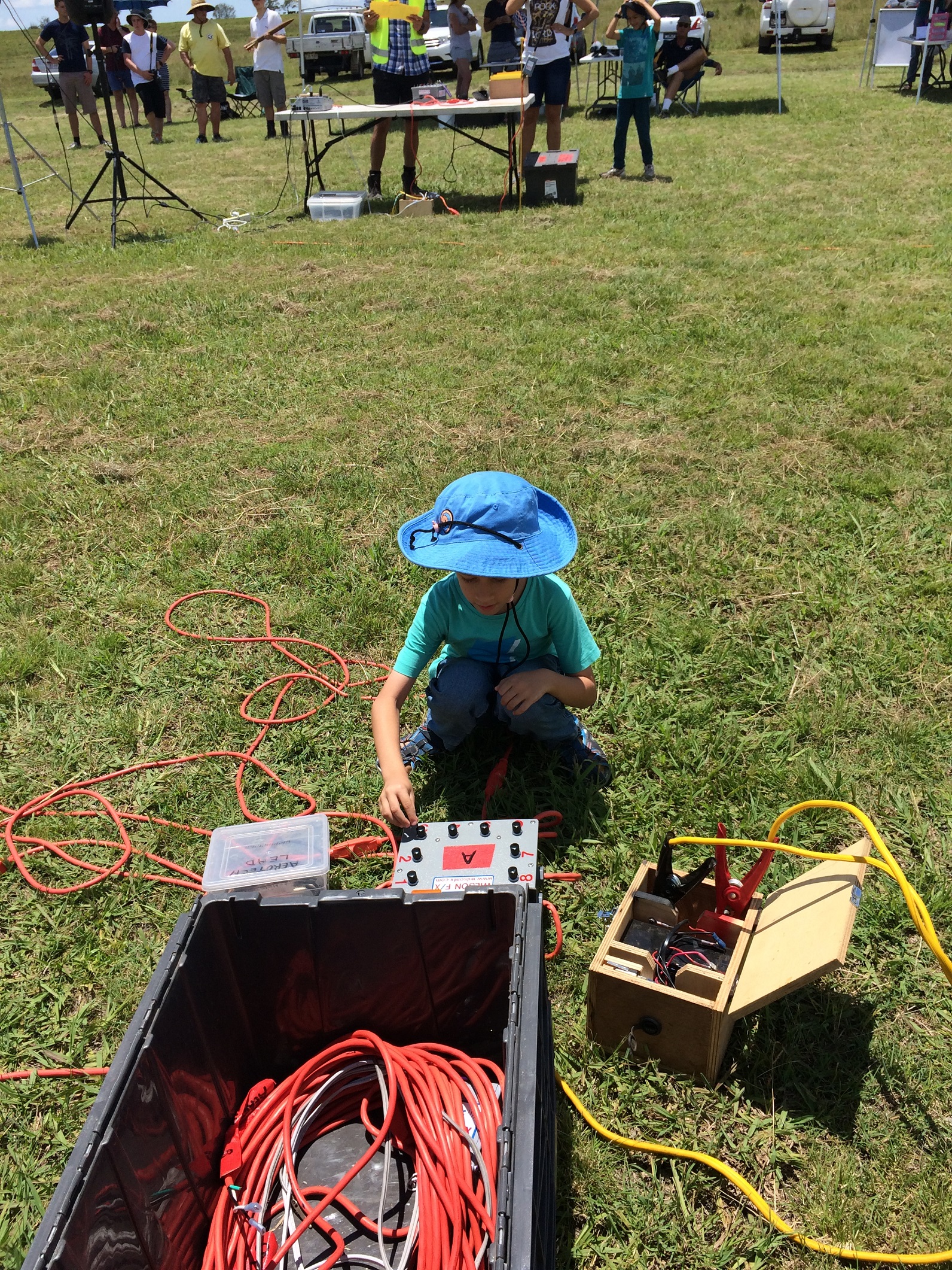
Isaac’s Rocket

Isaac flew a Small 15 Gram model rocket with a B-Engine. He was initially very scared of the noise and wanted to sit further back with the cars. Eventually he got the courage to participate in the rocket launching. Very pound of you Isaac!

Here are some pictures of Isaacs rocket and the boy himself!
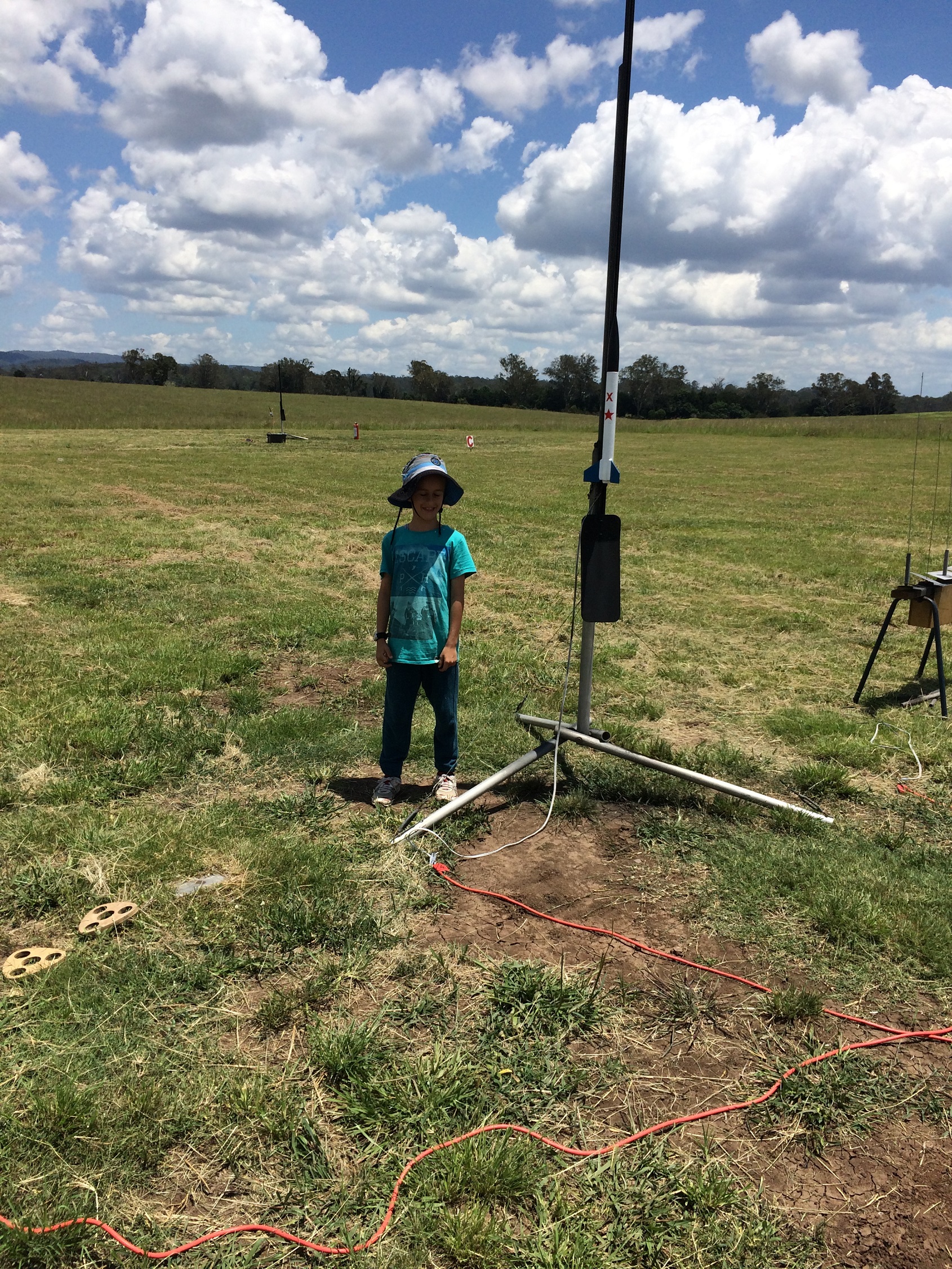
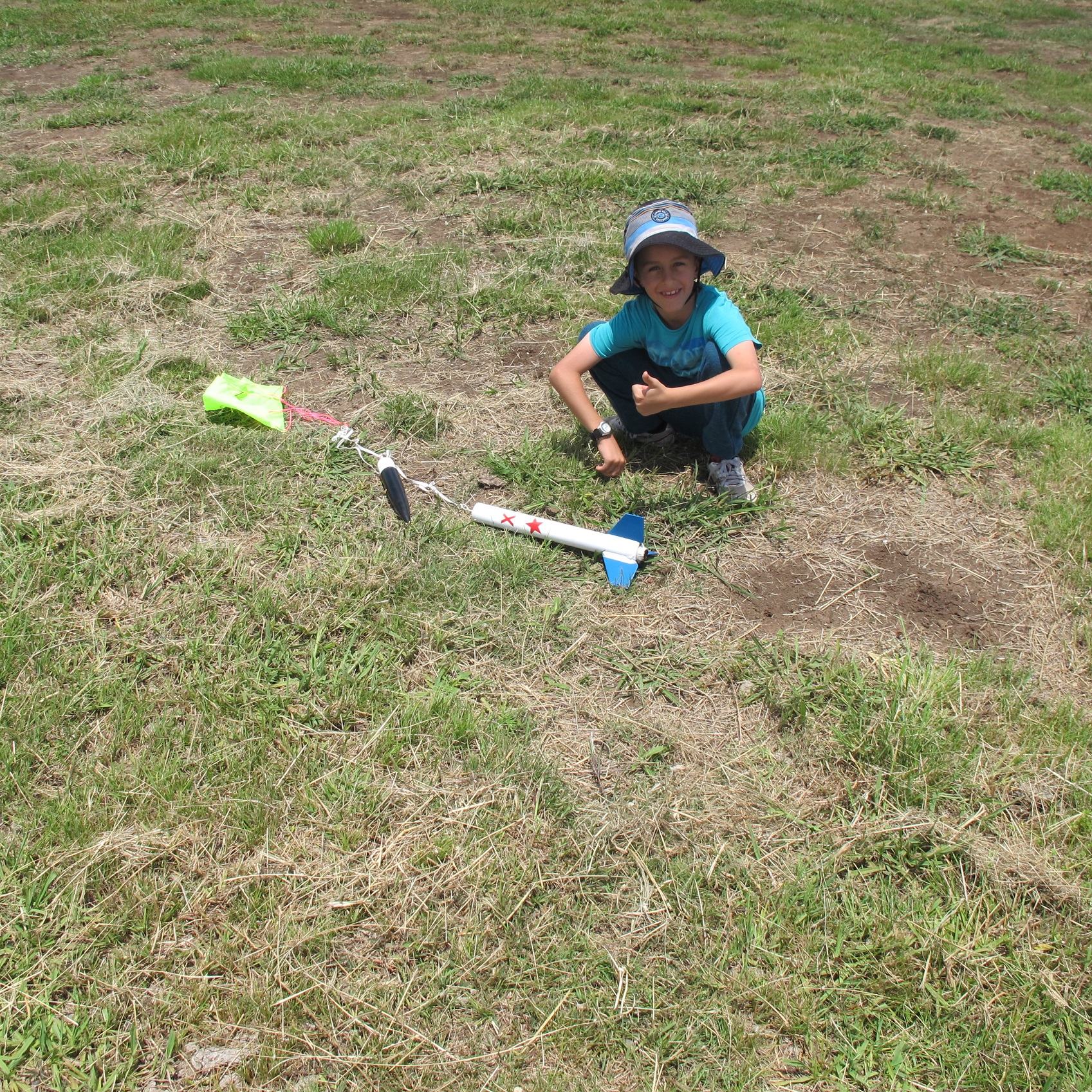
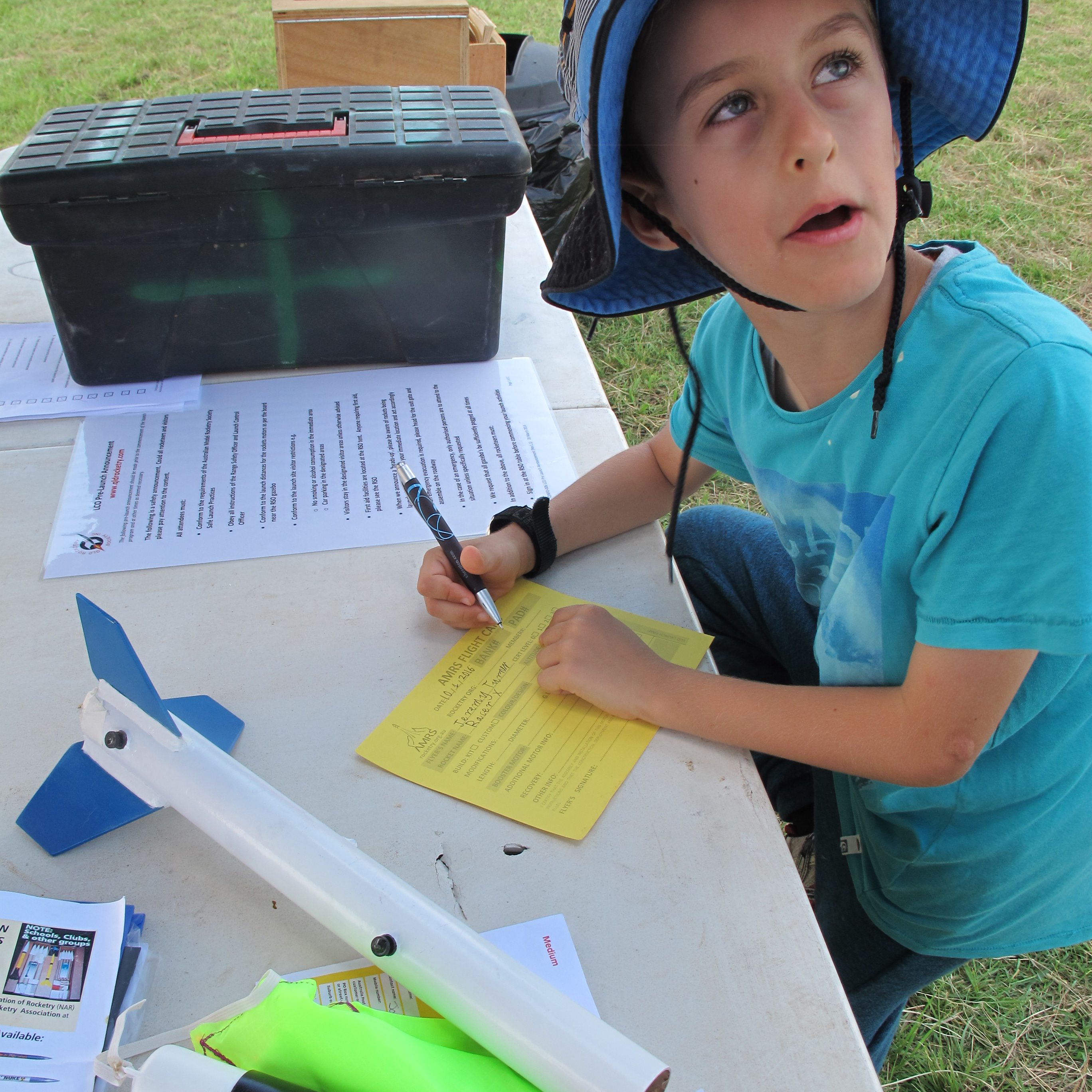
Isaac hecking the continuity of his rocket launch line


Isaac's rocket is one with blue nose cone
Isaac’s rocket is one with blue nose cone
Isaac with his Grandpa
Three rocketeers!
Three rocketeers!


Jeremy’s Rocket

Jeremy’s rocket is an exceptional rocket for a first timer. This rocket had a D-engine expertly installed by Blake (Owner of Ausrocketry). It deployed its parachute perfectly! Lovely work Jeremy!

Jeremy with his rocket on launch pad
Jeremy recovers his rocket - all intact!
Jeremy recovers his rocket – all intact!
Jeremy filling out his launch card

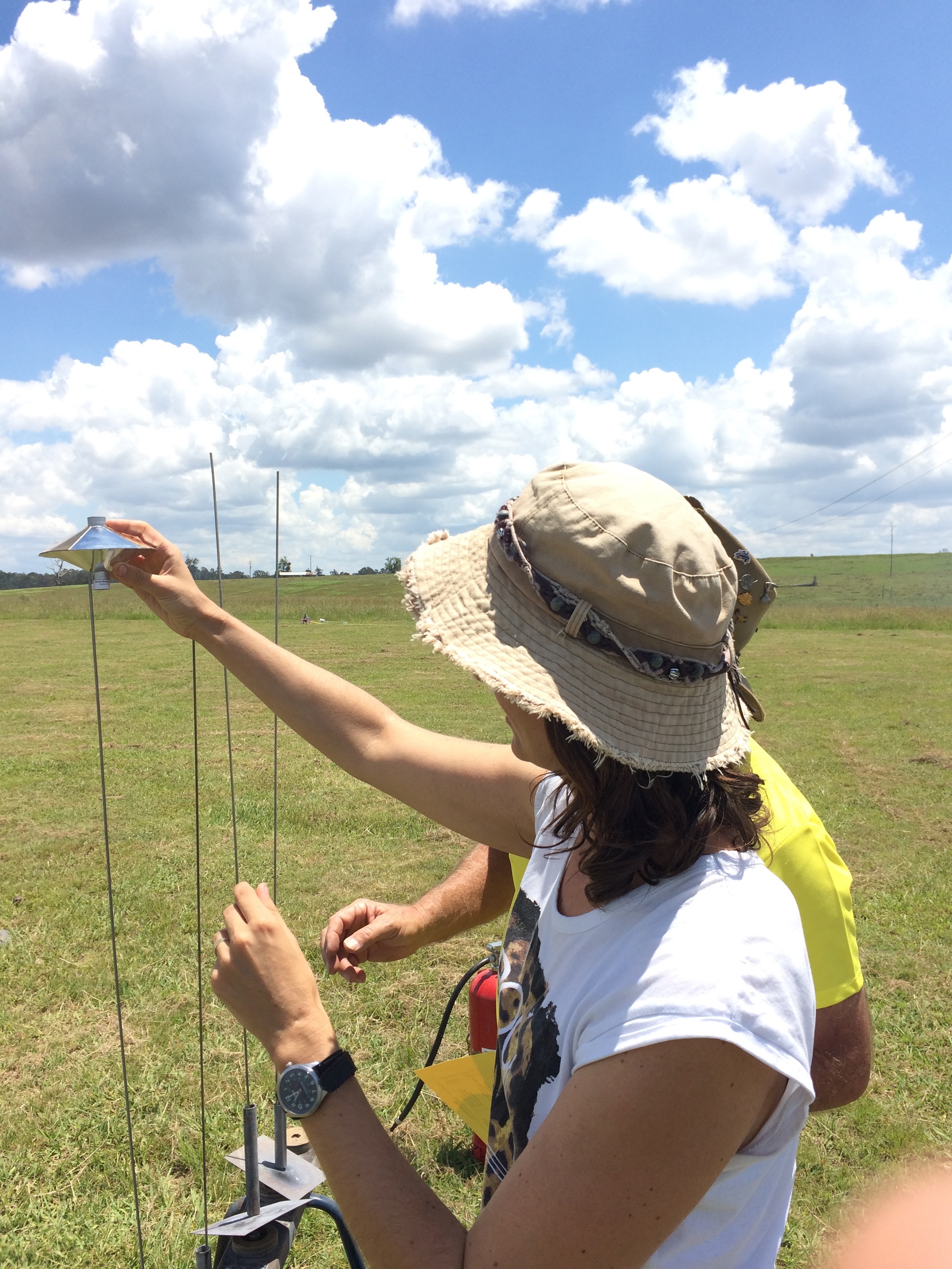
Anna’s (Mummy) Rocket (UFO)

Anna couldn’t miss out on the action and launched a UFO rocket. This had a C-Engine in it. It flew really well!
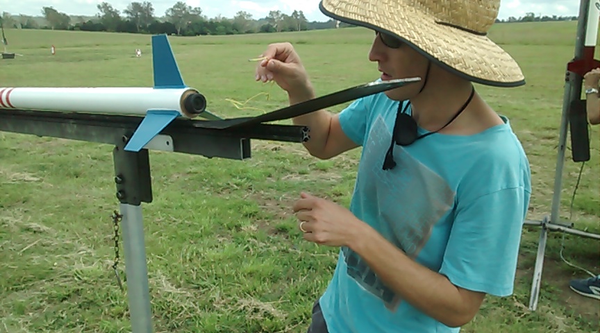
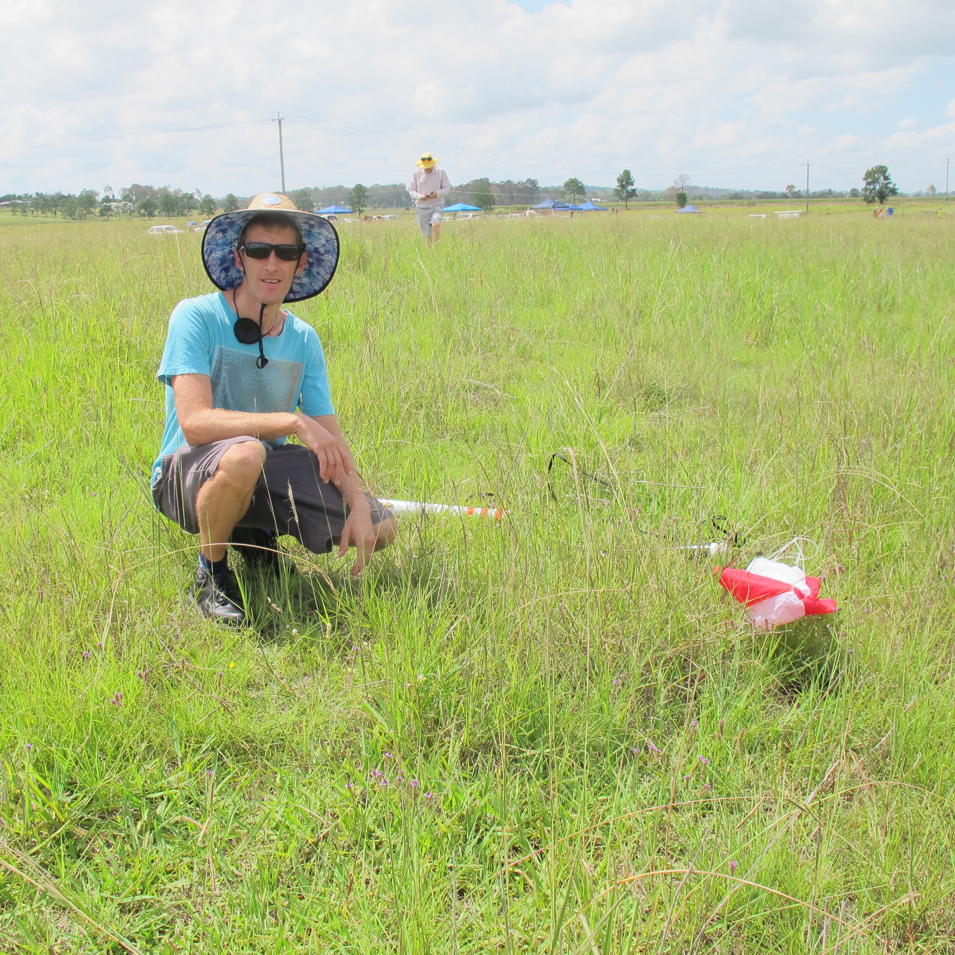
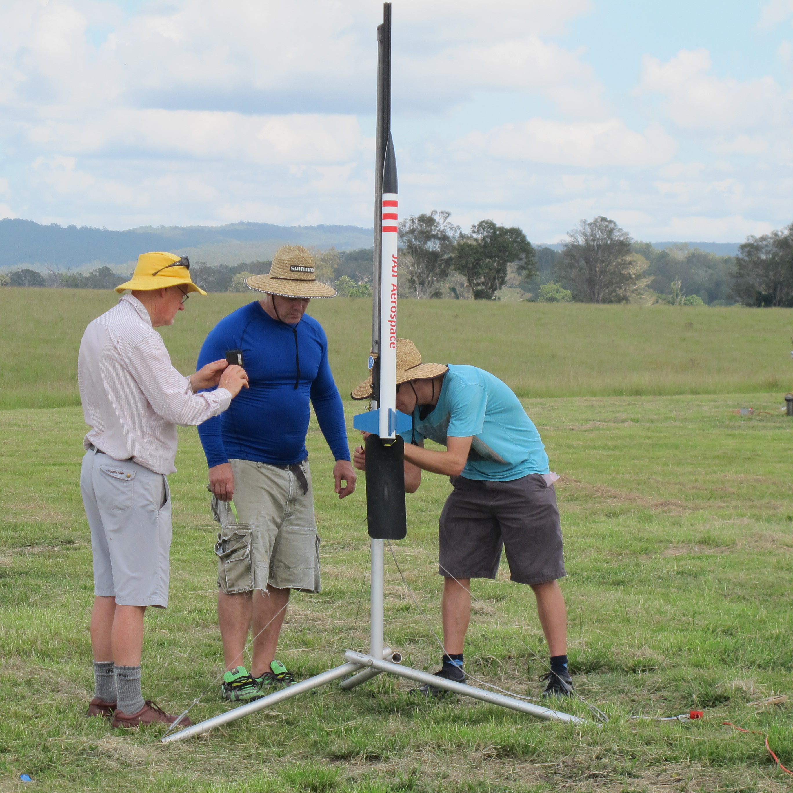
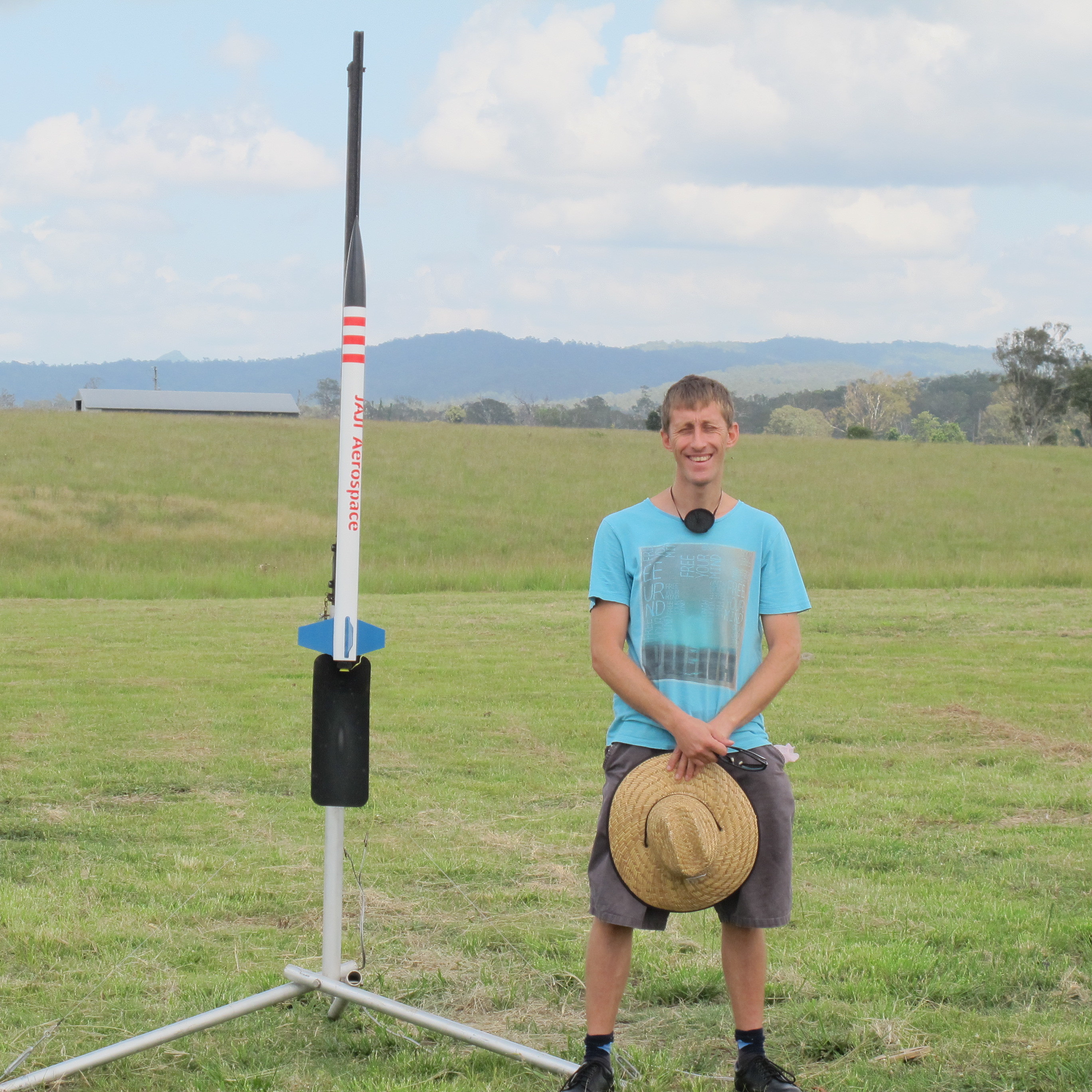
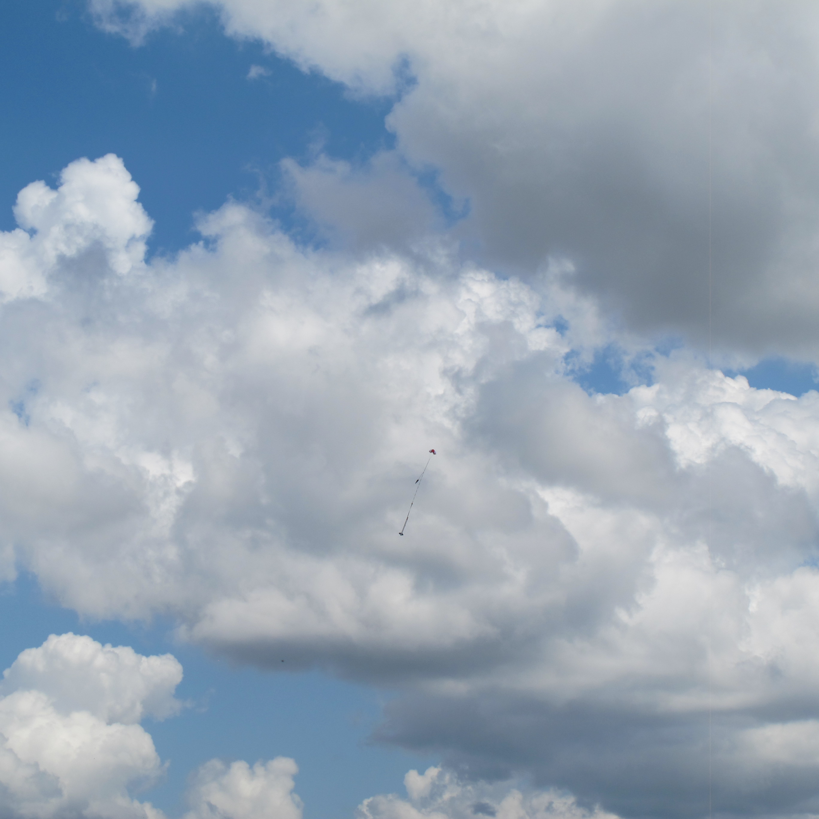
Anna carefully setting up her 'Rocket' for launch.
Anna carefully setting up her ‘Rocket’ for launch.


Joe’s L1 Attempt

Well I decided to go for my L1. This was very exciting. It took a lot of time to set-up the engine, even though it was just a CTI engine! I was taking things very carefully. Didn’t want to make any mistakes.

Inspecting the business end.
Jeremy standing next to my rocket where it landed
Found my rocket. All perfectly intact and only about 100 metres from launch pad.
Setting up the Ignitor
Ready for launch photo shoot.
Successful parachute deployment

What a great day!

Painting the Rocket

Next step was to paint the rocket.

A number of designs were done up using Blender. I did this by measuring the rocket and creating a file. I then played about with different combinations. Below are some examples.


One of many designs.
Jeremys top design
Jeremys top design

I also managed to figure out how to put some ‘text’ on the rocket tube to realistically show how it would look. Jeremy my son provided some possible designs and we ultimately adopted one of this designs; the last one shown.

The painting process was long and complex. There were times when I had to walk away to allow it to dry and then turn it over to paint more. Often I did very light coats, so as to avoid dripping. This meant I had to come back and do several coats though.

The basic steps followed were:-

  • Sand and clean up any imperfections in the rocket
  • Create a clean/free area (our garage) and put down newspaper
A place to paint
A place to paint
  • Prepare rocket on stands, with nose cone slightly withdrawn from tube and taped up together (in recess).
  • Cover up areas of rocket we do not want painted
  • Completed painted with white Primer
With Primer
With Primer


  • Painted fins blue
  • Painted nose cone black
  • Painted body white
Covering up Nose code before painting tube.


Covering up Fins before painting tube.
  • Created stencil from a computer print out….using a scalpel blade. Carefully placed on rocket. Also attached bands to make the red stripes
Carefully cut out
Carefully cut out


  • Carefully painted red writing and stripes.


Almost ready to attach stencil


Part way through painting lettering and stripes.


  •  Very VERY carefully remove tape and paper to reveal the finished item.


Painting has finished


Creating fin fillets

To ensure a strong rocket, we need to add fillets to the fins where they meet the Quantum tub on the inside and where the fins meet the Motor Mount.

First we removed the Aft Ring (pulling on the cellophane tags). This reveals the inside as shown below.

Removed Aft ring to allow us to create Fin fillets


We then created a small batch of 5-minute Areldite and started to create a fillets. (3 x 4 = 12 fillets) in total. We used some doweling to get the Areldite all the way from the front end to the back. It was a messy job and it was hard to stop getting glue everywhere, but we tried hard. We made a special effort to stop any glue getting inside the motor mount and if any glue got on the outside of the motor mount (at the back end), we quickly wiped it off with a rag. We did this because we need to be able to insert the motor and we need to be able to put on the motor retainer.

Once this was complete, we then needed to put the AFT Motor Ring back into the quantum tubing with sufficient amount of Areldite to ensure it would not come out.


What can we learn from this?

While the external fillets created are strong and will definitely hold the fins in place, because there is no camber (concave surface), we have an abrupt change in surface direction and this will invite turbulent flow and so drag. This probably won’t be detrimental to the flight, but the maximum altitude won’t be attained. Something to be mindful of in L2 and other future rocket builds.

The Motor Mount

The rocket motor doesn’t get attached directly to the Callisto’s Quantum Tube. The motor is inserted into the motor mount tube. This ‘motor mount’ (a cardboard tube) is secured inside the Quantum Tubing with some circular rings that are glued. These rings themselves are also glued to the motor mount tube and we have the Piston strap (A strong thick black cord) securely glued to the motor mount. Some pictures of the construction of this component are shown below:-


Using 5 minute Areldite to glue the forward motor mount ring


We created fillets around the motor mount ring to ensure it will not budge during flight or ejection.


Notice the ~1 inch slot. This is for the Piston Strap.


We took care here to ensure we did not clog up the slot. We insert the piston strap into this slot later on and Areldite it in place.


Put Celopane around the Aft Motor mount Ring


All rings put on to Motor Mount


Securely attaching the Piston Strap to the Motor Mount.


After the Piston Strap glue had tried, we packed it inside the motor mount to keep it out of the way in the next lot of steps.


Next step was to start gluing the Motor Mount to the rocket tube. We put some Areldite ~7inches into the back of the rocket (in a ring) using some long doweling. We then pushed the Motor Mount all the way in, till the appropriate amount was sticking out. (We are using HAMR motor mount, so we need to leave sufficient amount of space to attach Retainer on to the motor mount). We had to leave the rocket in a vertical position to allow the glue to flow down and remain against the motor mount top ring.

Jig for Rocket Fins

I started bulding the rocket up by first making a jig to keep the fins orientated 120degrees apart. I decided this was critical for a successful flight and so did this immediately. Some pictures are shown below of this.

Ply Wood with hole cut into it, Just large enough for Quantum Tube to fit in


Quantum Tube fits snuggly inside Plywood hole


Cuts made in Ply wood at 120 degrees allow correct positioning of fins in Quantum Tubing.

I had to sand the cuts in the plywood with sandpaper to widen the gap to allow the Fibreglass fins to snuggly slide in them.

Receiving Parts for L1 Rocket

I carefully chose a rocket to gain my L1 certification. I wanted to get a rocket that I could also use with smaller rocket motors (which means I can legally fly it). Once I have my L1, I can then legally fly it using  larger rocket motors. The rocket I choose is a Callisto which I got from http://ausrocketry.com.

Below are some pictures of the parts carefully extracted from the delivery box and spread out for each viewing and inspection.


SML_IMG_5869
While Rocket unopened. Contains Long Grey Quantum Tube which is the main air frame.
SML_IMG_5870
Fins, Instructions in plastic bag, “Launch Guide Buttons”, Piston strap, Shock Cord, Piston, Parachute and Nose Cone


There were a lot of additional items required to build the rocket:-

  • 5 Minute Areldite
  • A scalpel
  • Paddle pop sticks
  • Sellys Epoxy Putty
  • 120, 240, and 400 grit sandpaper
  • Masking Tape
  • Dowling
  • Block of Wood (for mixing Areldite on)
  • Sticky tape
  • Pencil
  • Black Marker
  • Ruler
  • A large clean workspace with good light