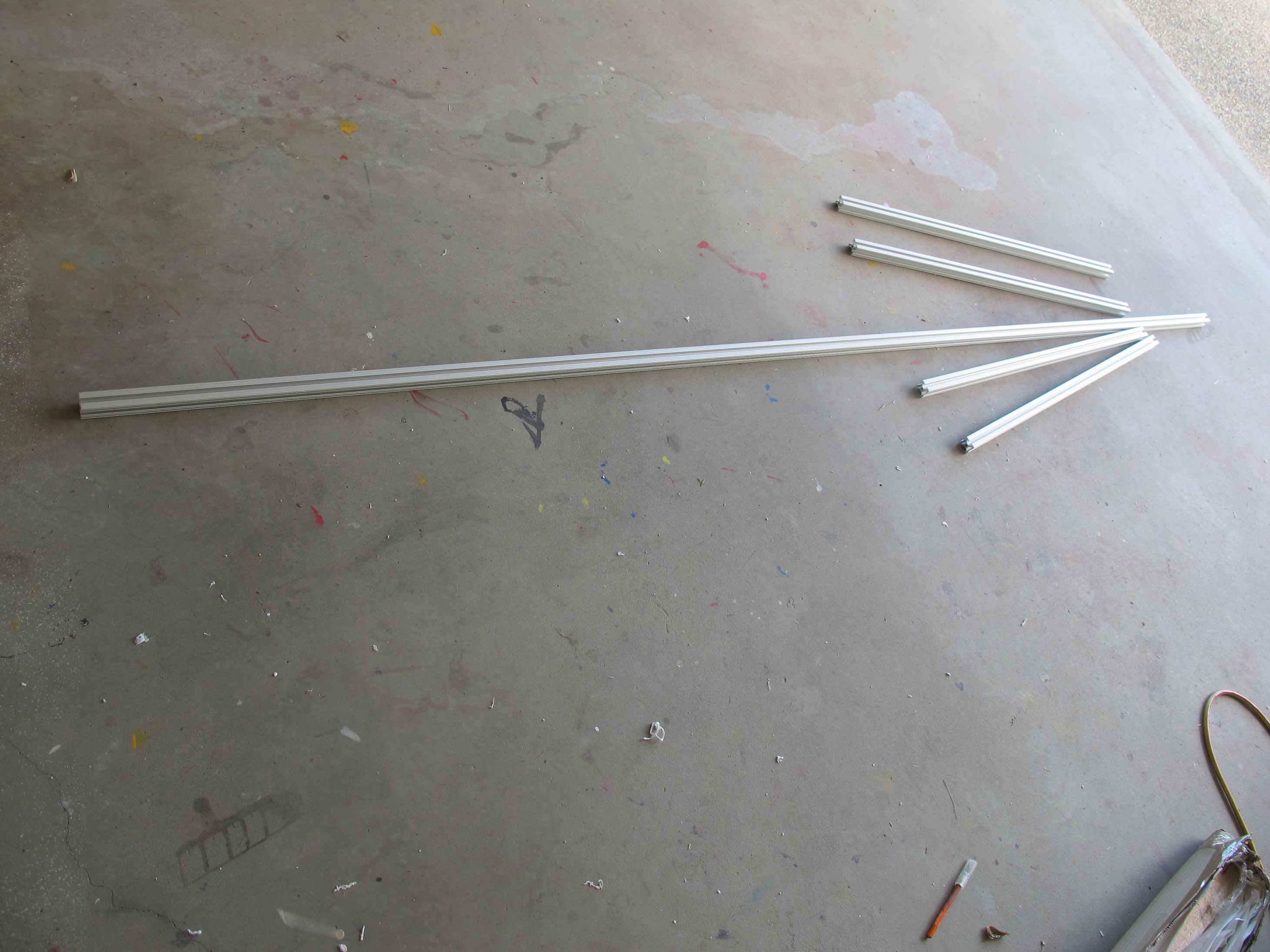
Just a short post to show the launch pad with the launch rail attached to the platform. It is a 2.5 m length of 1010. I still need to put in a blast deflector and a stopper for the rocket to rest upon. Here are some pictures
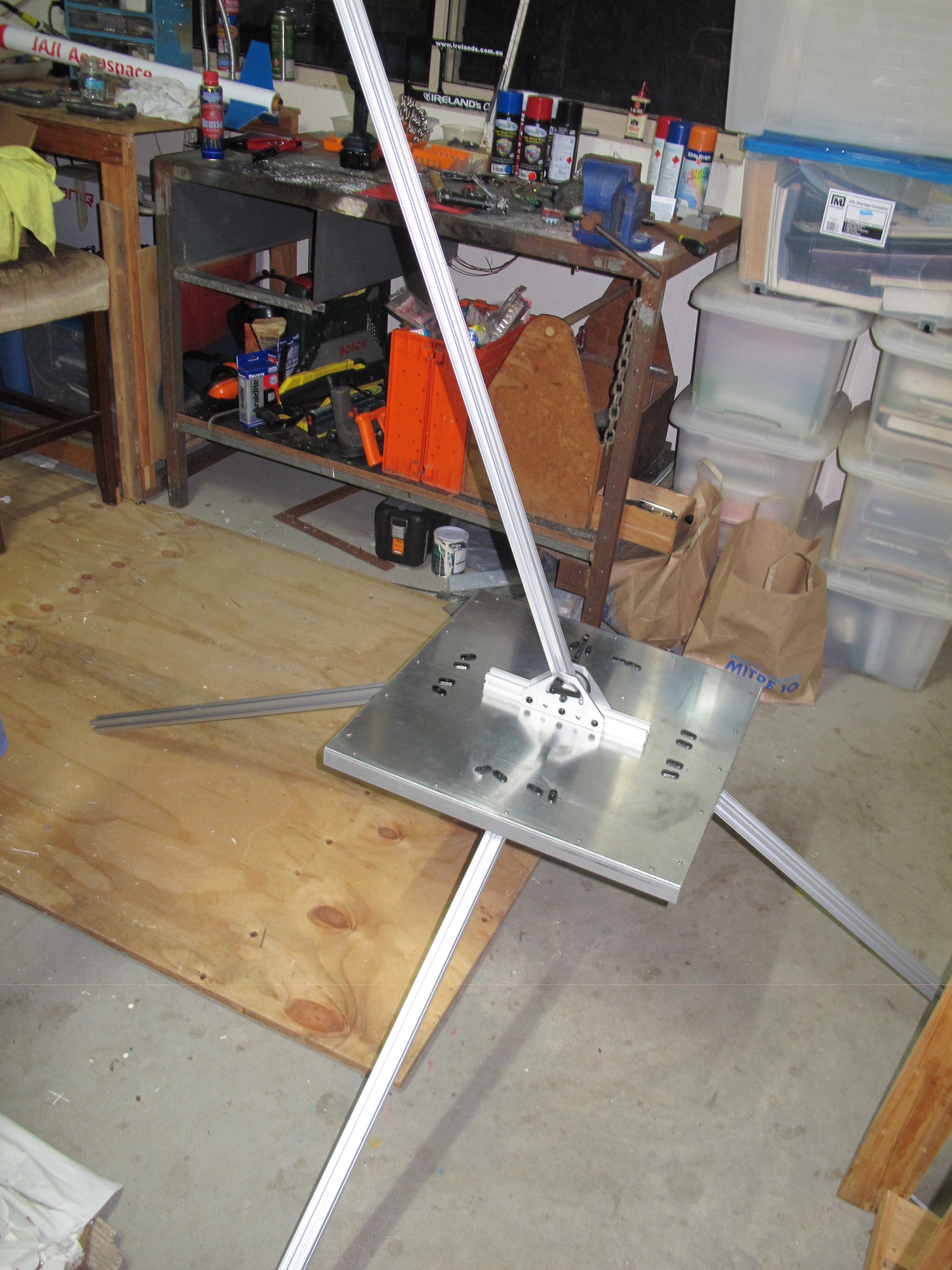

Construction of 8020 (1010) launch pad
Just a short post to show the launch pad with the launch rail attached to the platform. It is a 2.5 m length of 1010. I still need to put in a blast deflector and a stopper for the rocket to rest upon. Here are some pictures
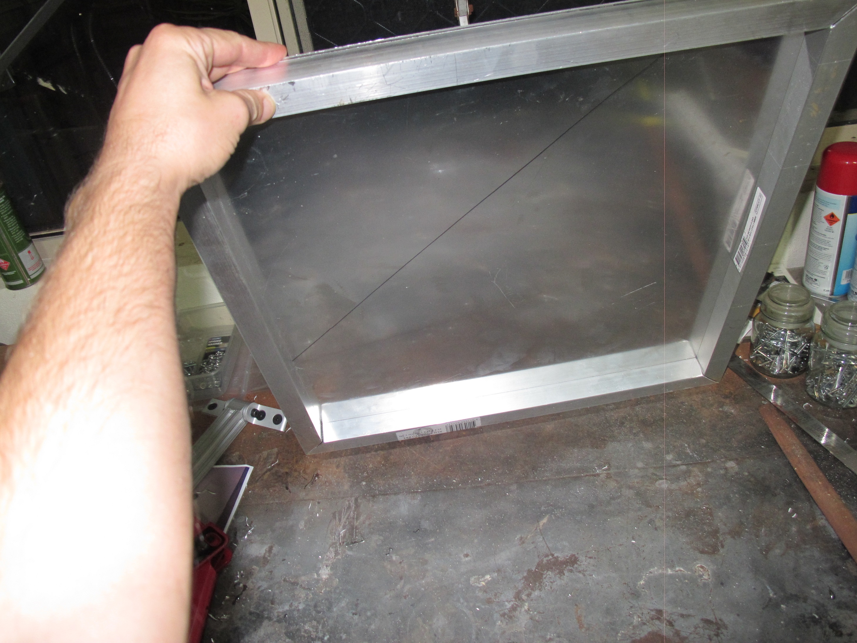
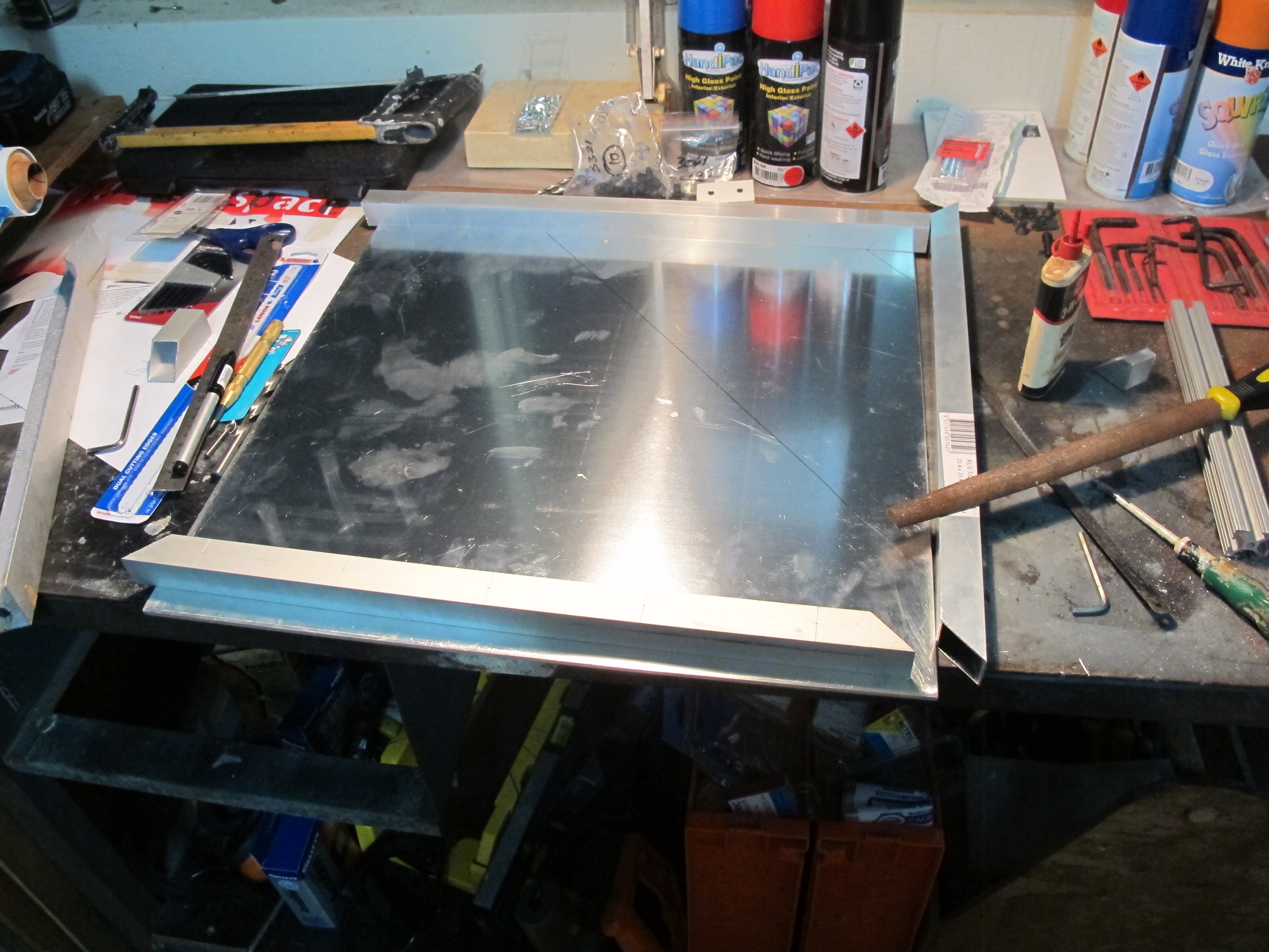
The platform sheet is particularly heavy and sharp and hence dangerous to handle. It is very easy to cut oneself on the edge of it. To deal with this, we have decided to attach 1″ square profile Aluminum tube. We have done this by cutting four lengths of tube and cutting out each end a 45 degree cut to ensure they connect together around the perimeter of the Aluminum sheet neatly. We pot riveted these square profile tubes to the sheet.
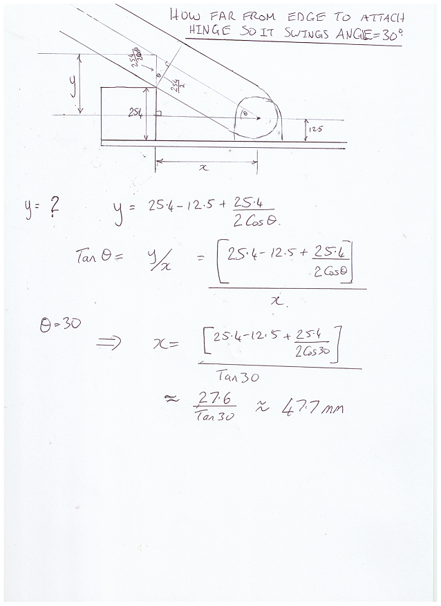
Next I wanted to install the leg hinges. I want the platform to be about 40cm above the ground and so with a leg length of 80cm, this means the legs must subtend an angle of 30 degrees with the platform. The side aluminum tube will provide a place for the legs to rest against to ensure 30 degrees angle is met. To get the angle of 30 degrees, we must place the legs a certain distance away from the tube. Please see calculations below.
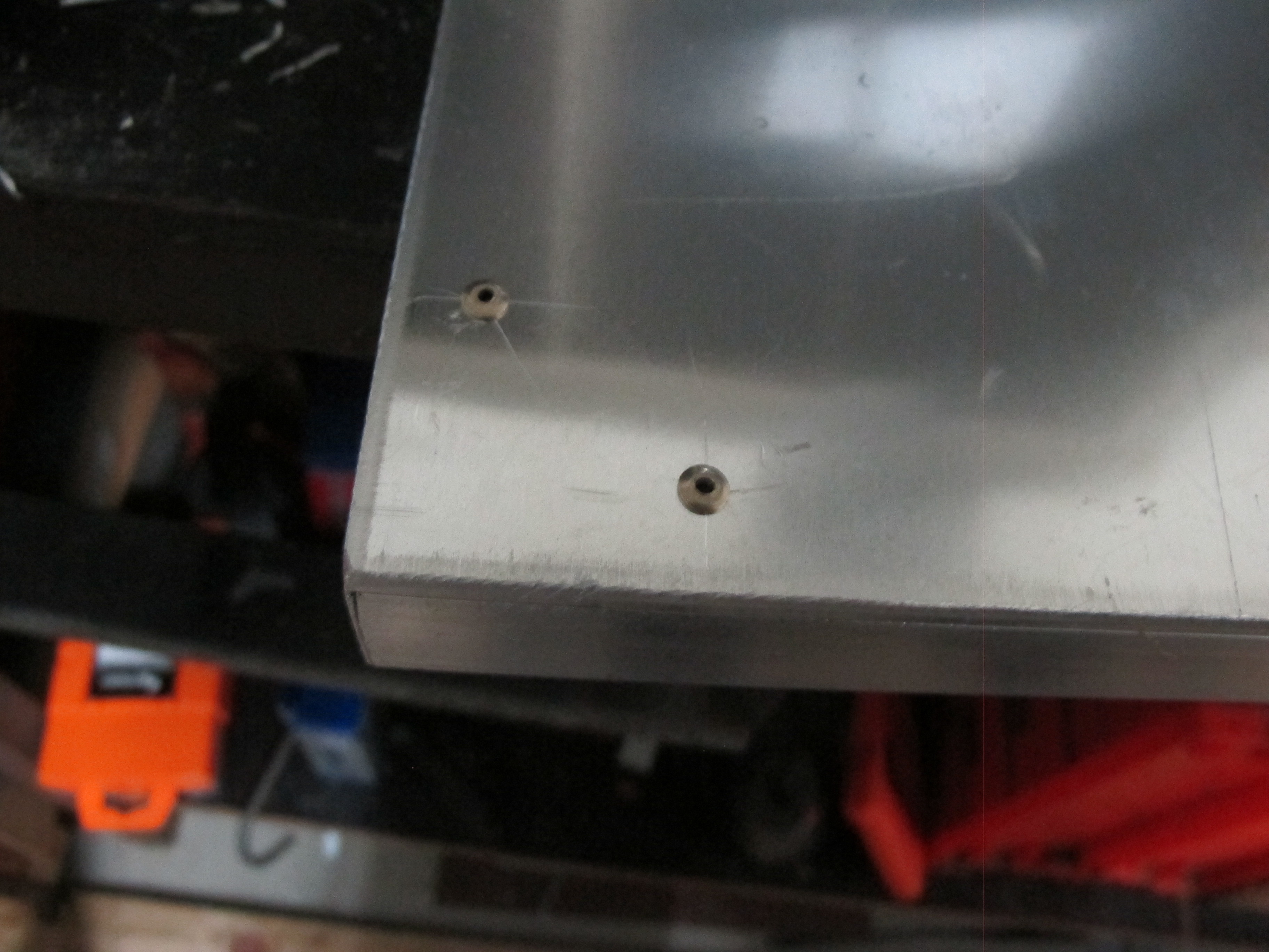
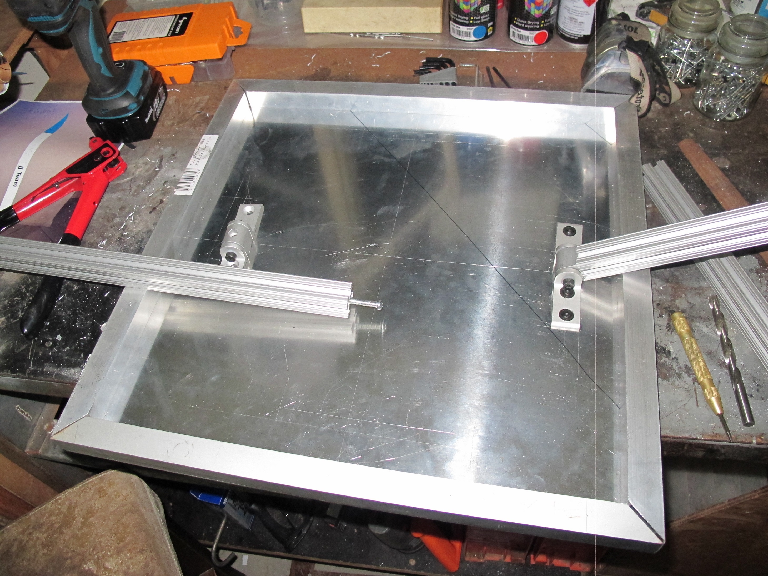
I’ve started marking holes around and installing the hinges. See the picture below.
The rocket hasn’t been completed…the launch buttons haven’t been installed. There is a reason I’ve decided to hold off on the install of the buttons/lugs is to complete the launch pads.
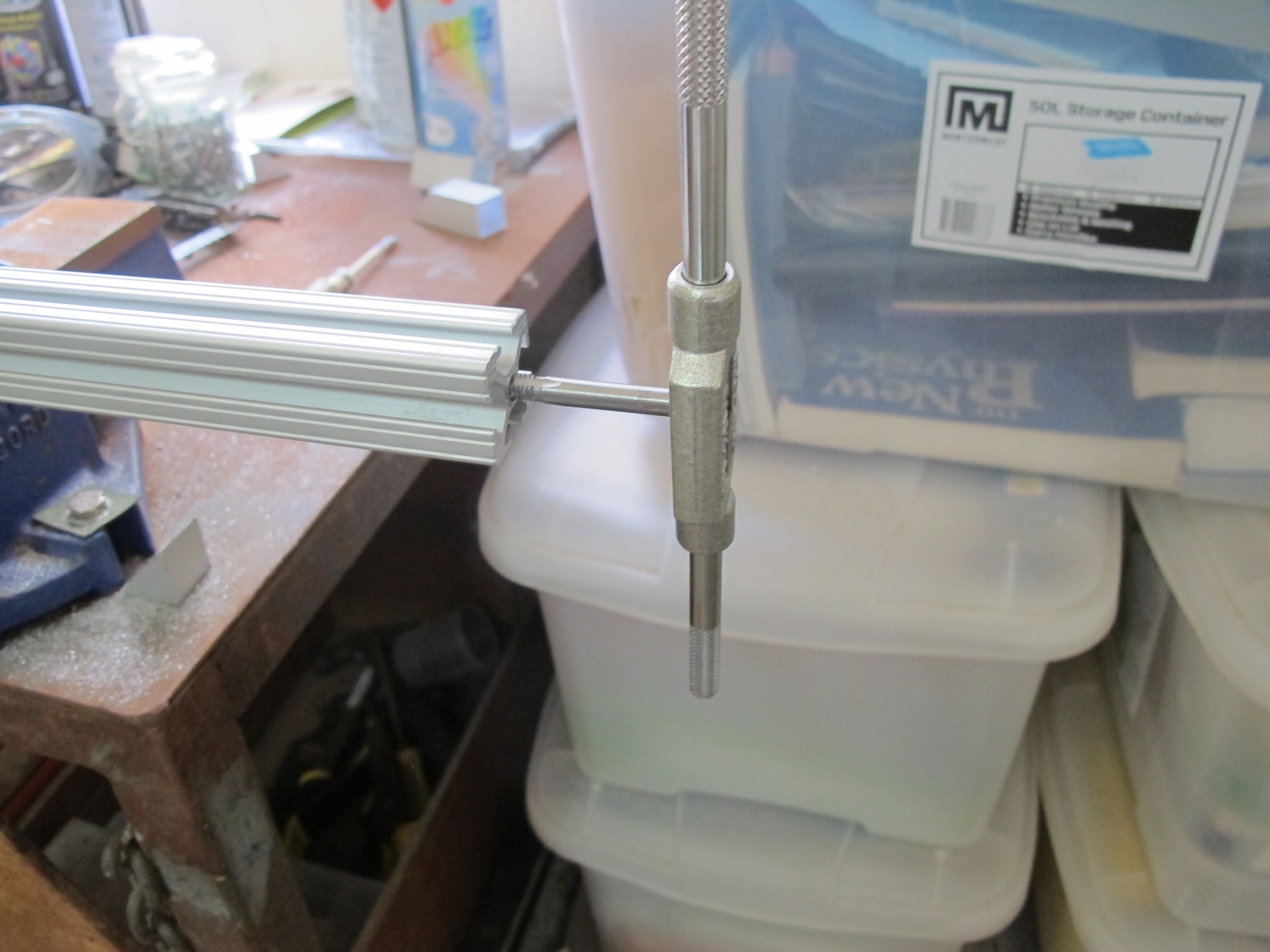
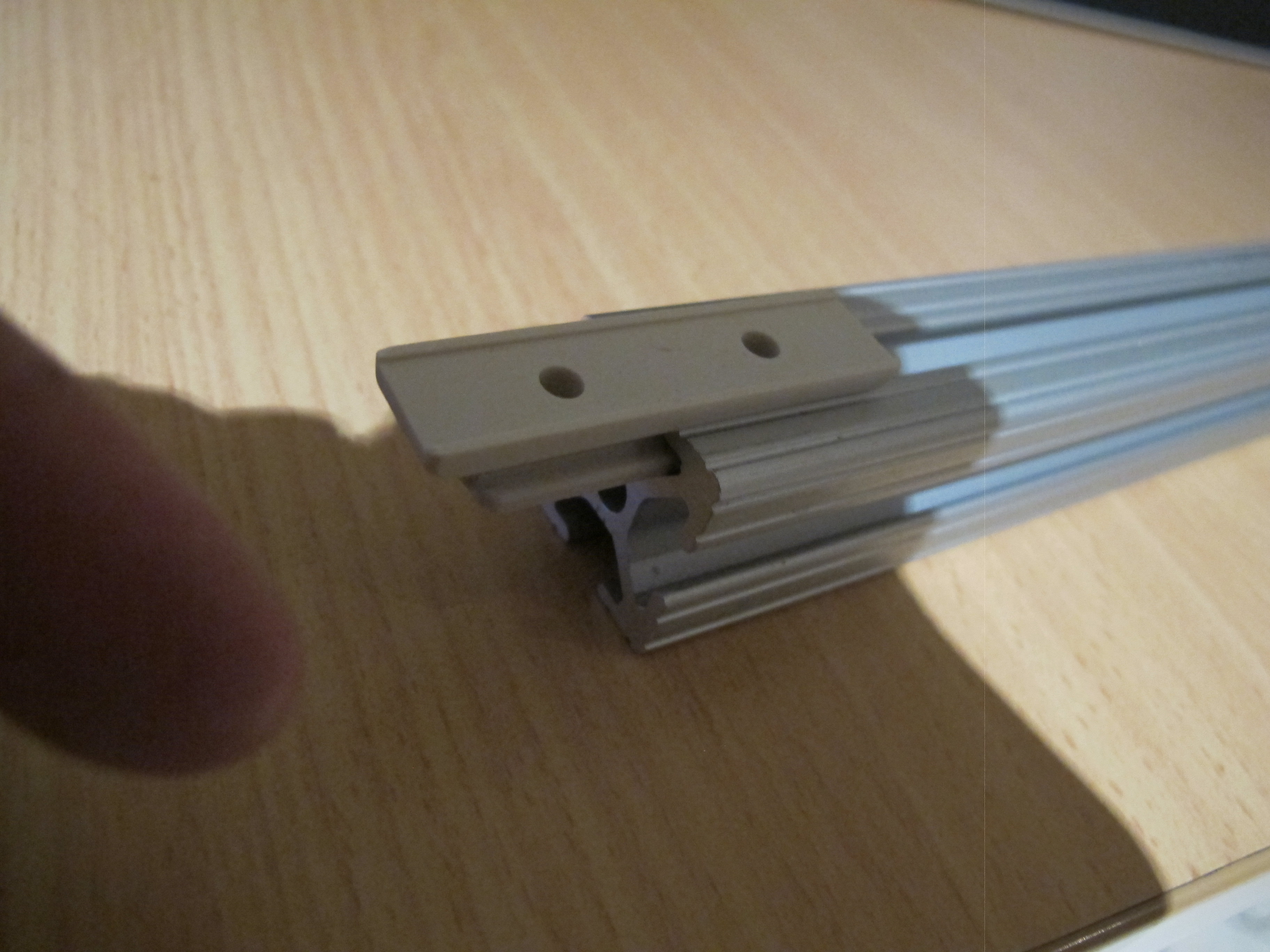
For those who do not know, the launch buttons/lugs are what we install on the rocket to guide it up the rail. See Picture below of a lug inside some 1010.
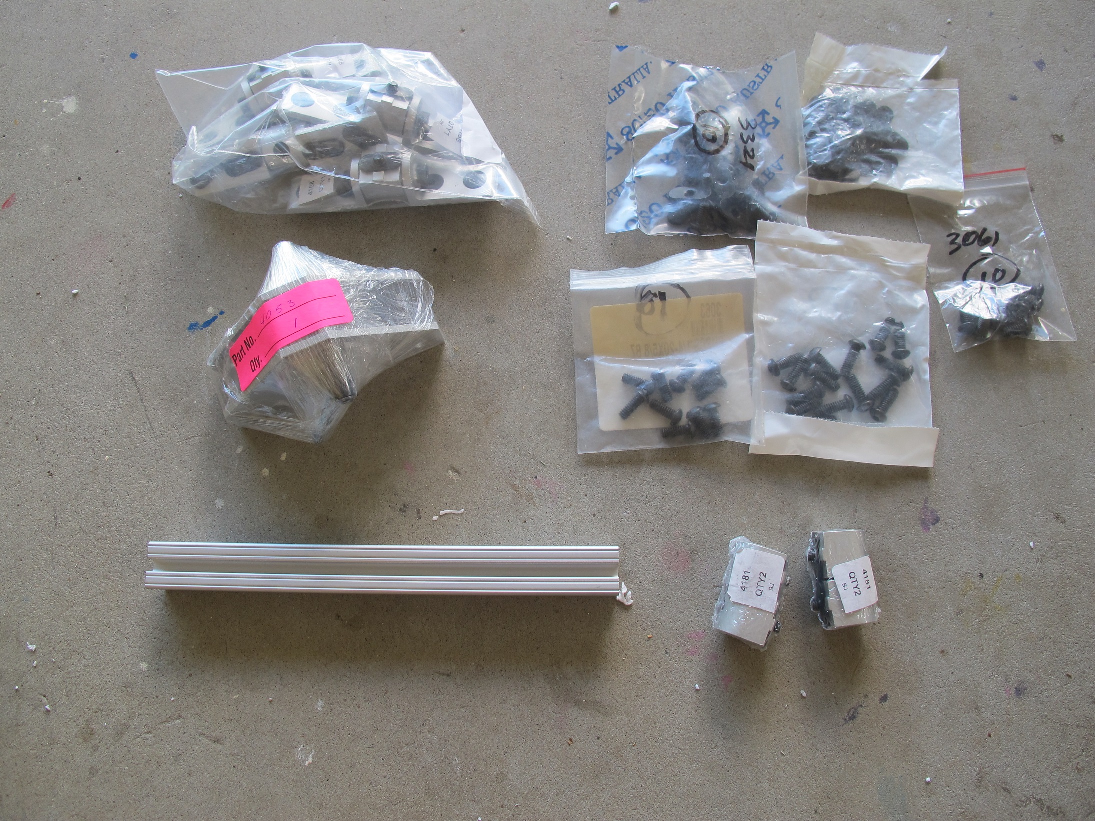
Anyhow, I’ve received all the parts from 8020 that I need. A mong these parts is:-
Pictures of these below.
I need more parts and tools to complete this part of the project. I needed to obtain :-
Below is a picture of the Aluminum sheet with some of the square profile pipe cut into pieces…almost ready for assembly around the rim of the square.
Below is a picture of me Tapping a M6 hole into the ends of the Legs.
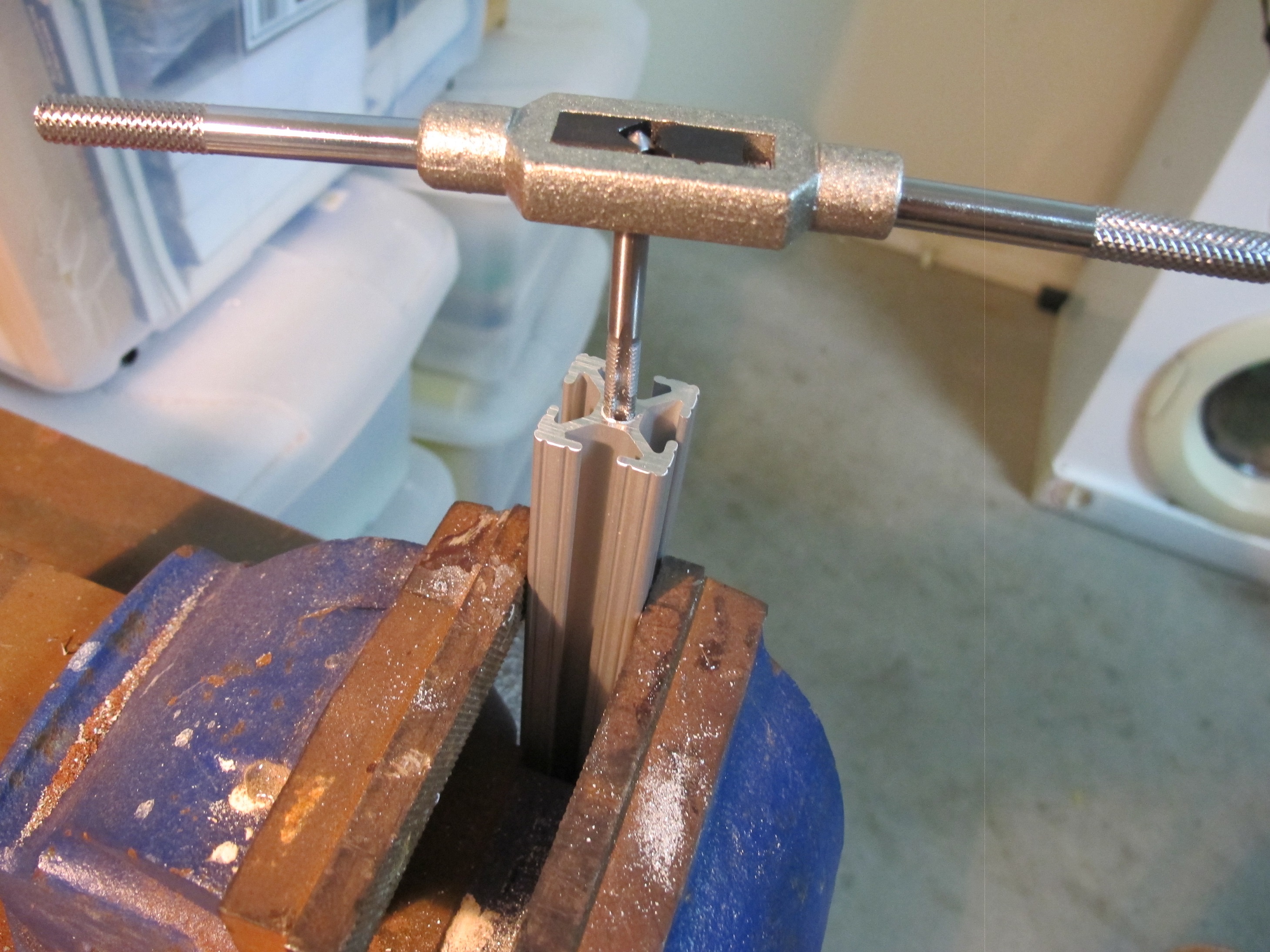
The holes were already 0.205 ” which is 5.207 mm. This is not too large for a M6 tap job.
Below is a picture of all legs with the Part #4168 attached.