Category Archives: Testing

Testing the Cable Cutter

The Cable Cutter

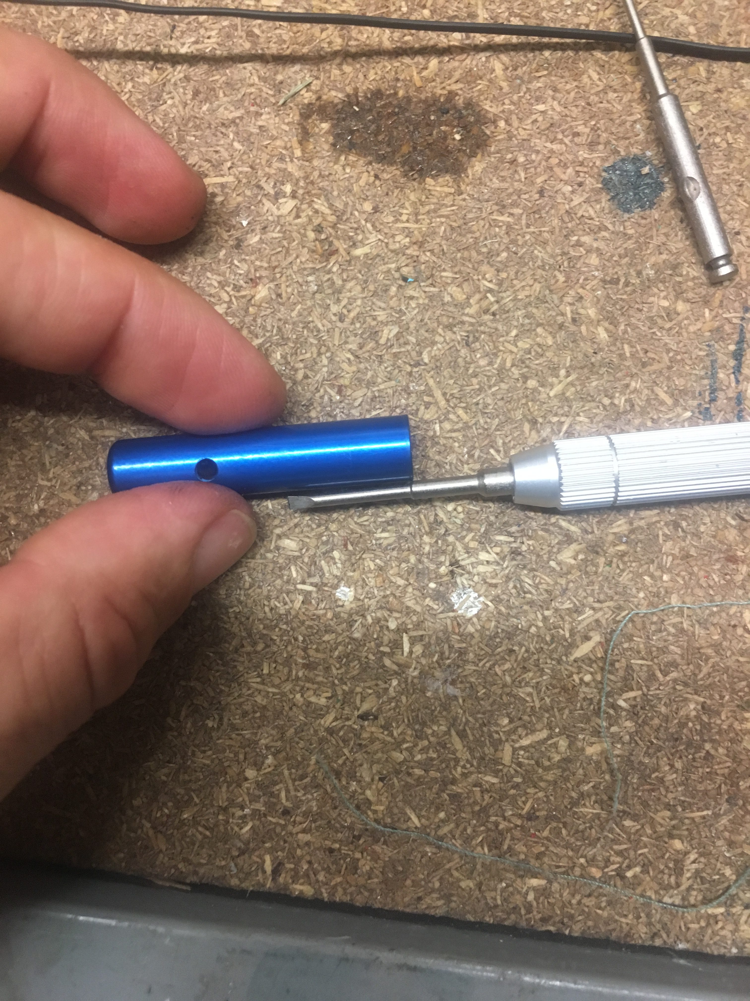
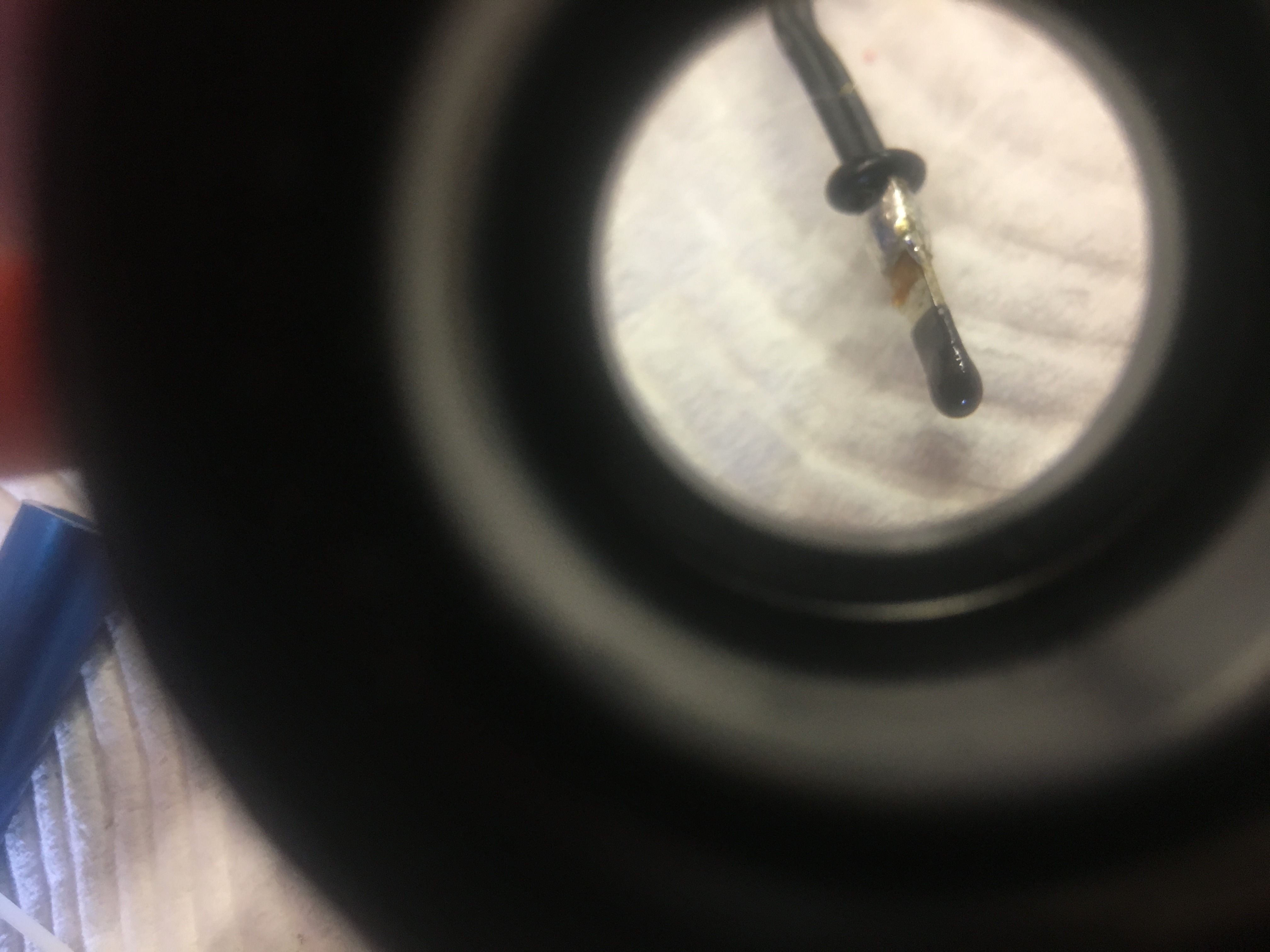
The Cable Cutter I purchased from Aerocon Systems has cambered edges as shown in photo below.

This should have a very sharp cutting edge...a concave hole.
This should have a very sharp cutting edge…a concave hole.

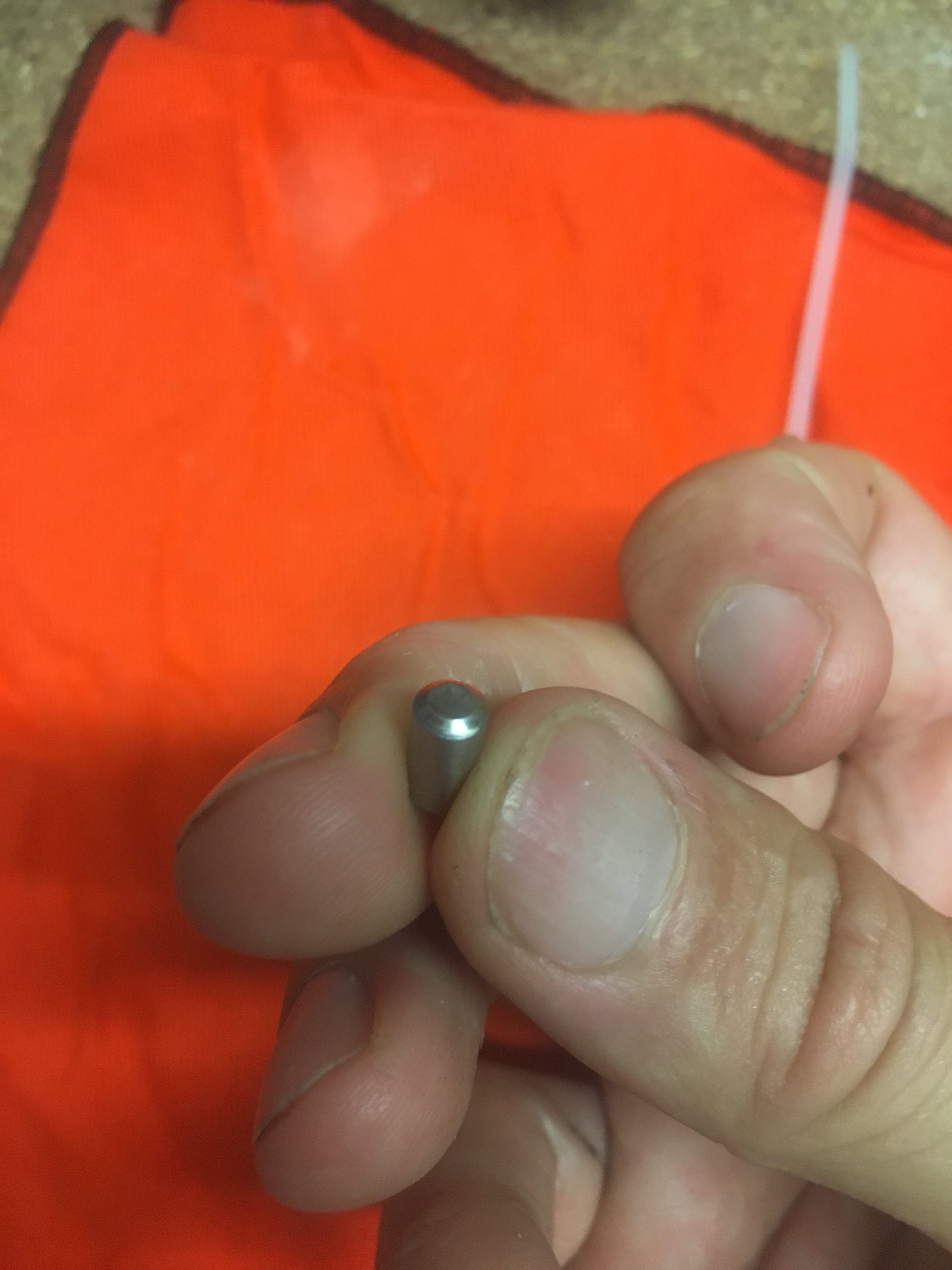
According the supplier, this is normal of these cutters now and is on purpose because the Aluminum cartridge gets damaged from the sharp edge of the piston when too much Black Powder is inserted.

Creating a Cutting Edge

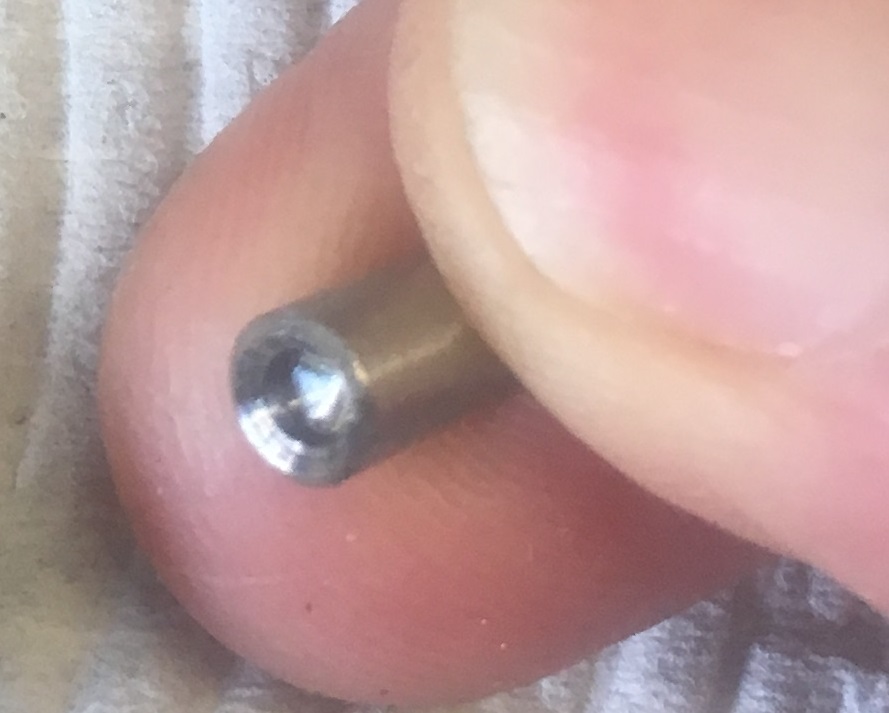
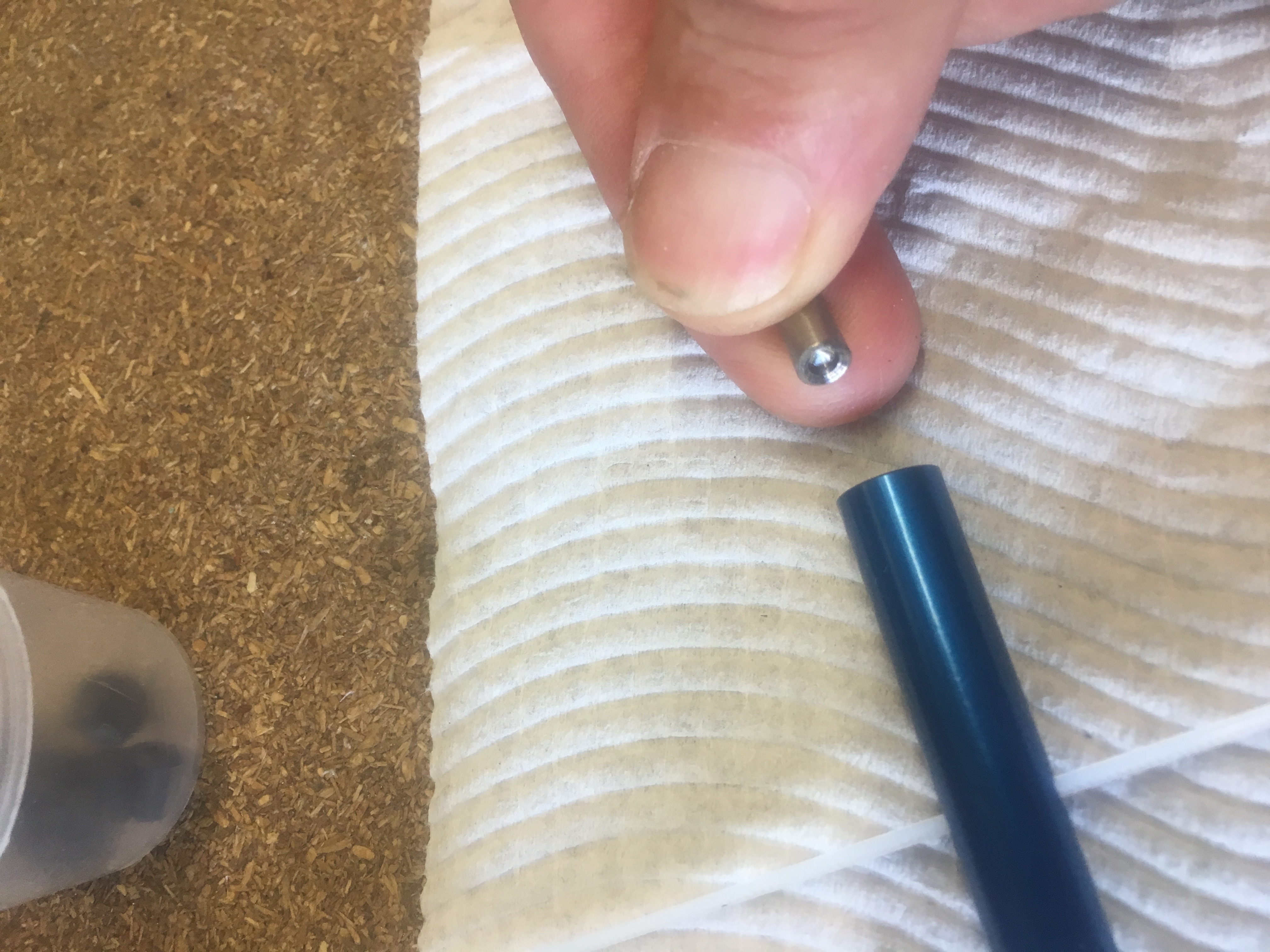
I decided that I would introduce some sharp edges because it just didn’t cut on my first test; and if it doesn’t cut the cable tie, it is of no use to me. So I drilled about 3mm into each end with a 2.5mm drill bit. Then I used a counter-sink bit to create a bit of a ‘crater’ with a sharp edge. See photo below.


3mm deep hole drilled with 2.5mm drill bit.

Precise steps were:-

I did this in the vice, very carefully using Aluminum brackets to not distort the steel piston. I marked the center point using pencil under magi light. Then I used punch to mark the center.

I went straight to the 2.5mm drill – special tip and used cutting fluid. It drilled just fine. Then after drilling to a depth ~3mm I used a countersink drill bit to go about 1mm in, to get a “cutting edge” just inside the main diameter.


Assembly

I assembled as follows:-

First goes the O-ring.


Threading the cable tie into the blue cylinder.
Slotting in the Piston.


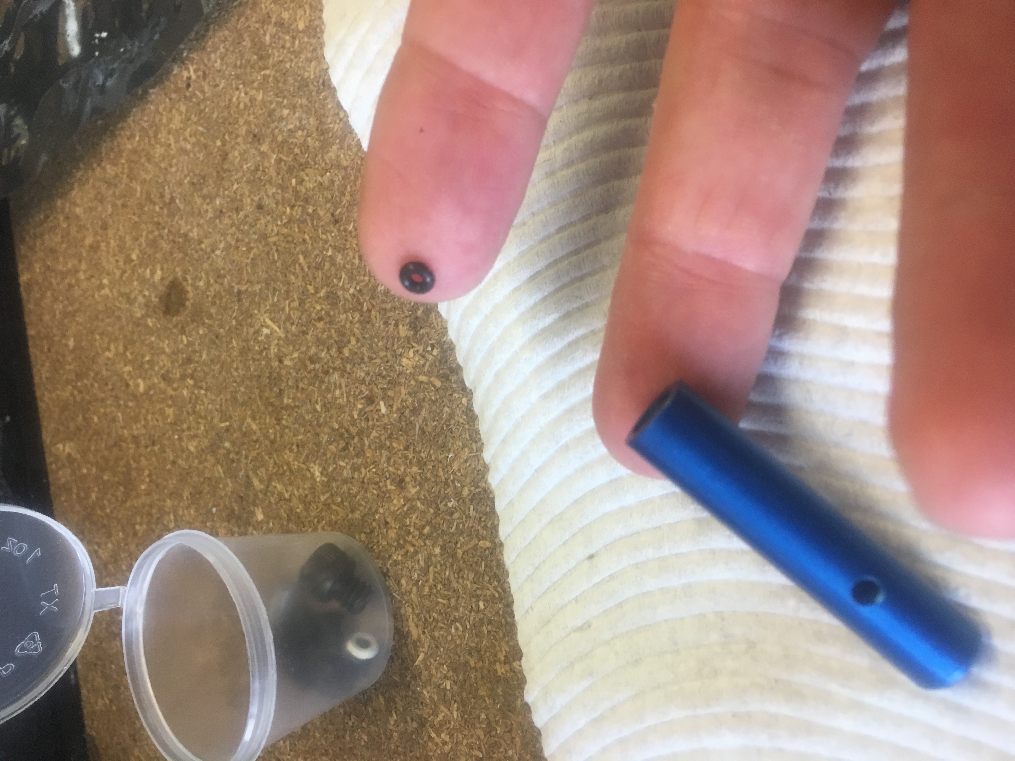
Next I straighted out the e-Match and took the red plastic protector off it. Then I rolled on a small O-ring. The O-ring has two functions:-

  1. To help seal the cylinder, reduce amount of gas coming out
  2. To stop shorting of the igniter contacts on the hex screw end bit.
Close up view showing the O-ring.
Everything fitted and plenty of hot glue melted on to end to ensure no gas comes out the rear.

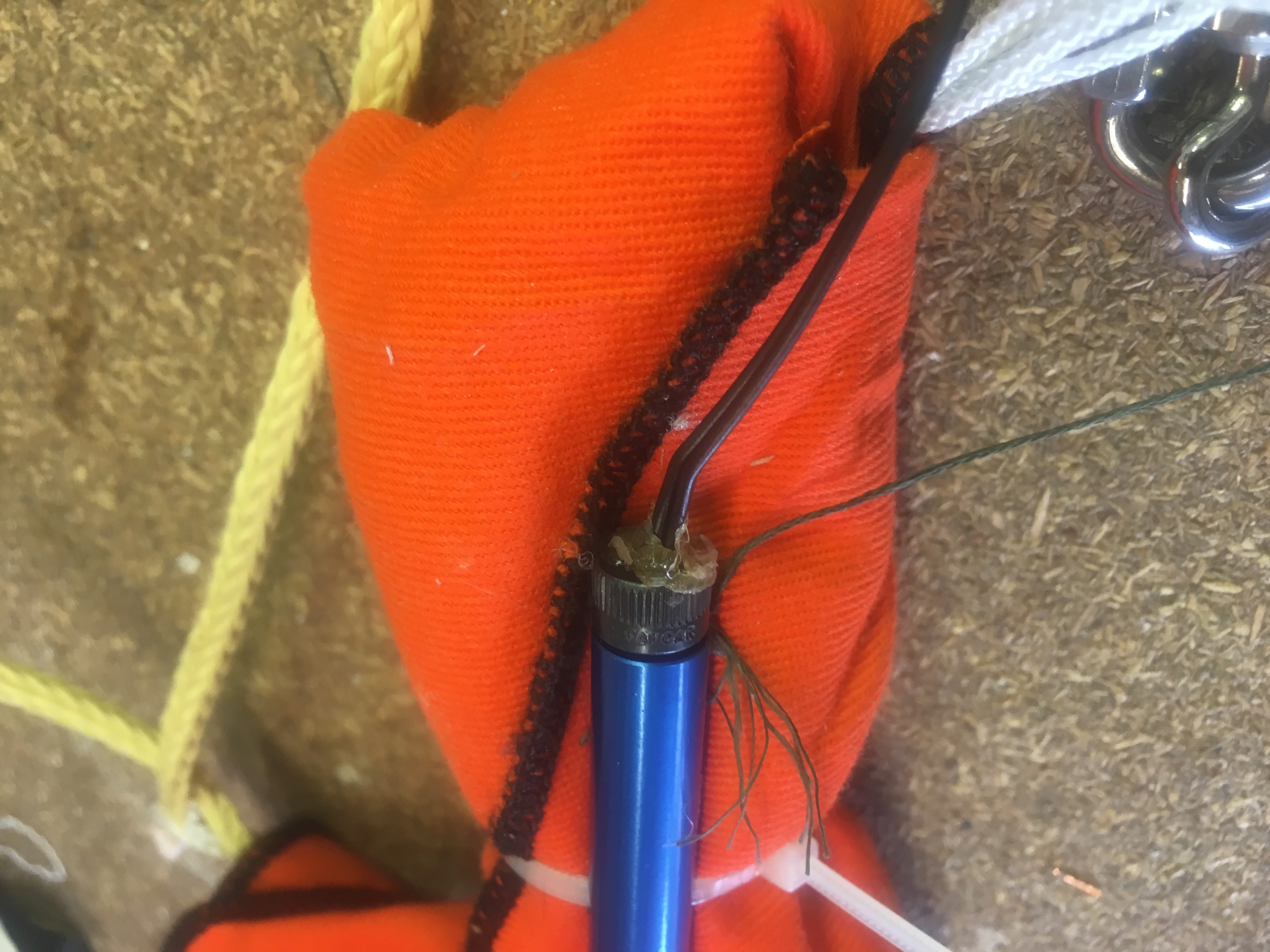
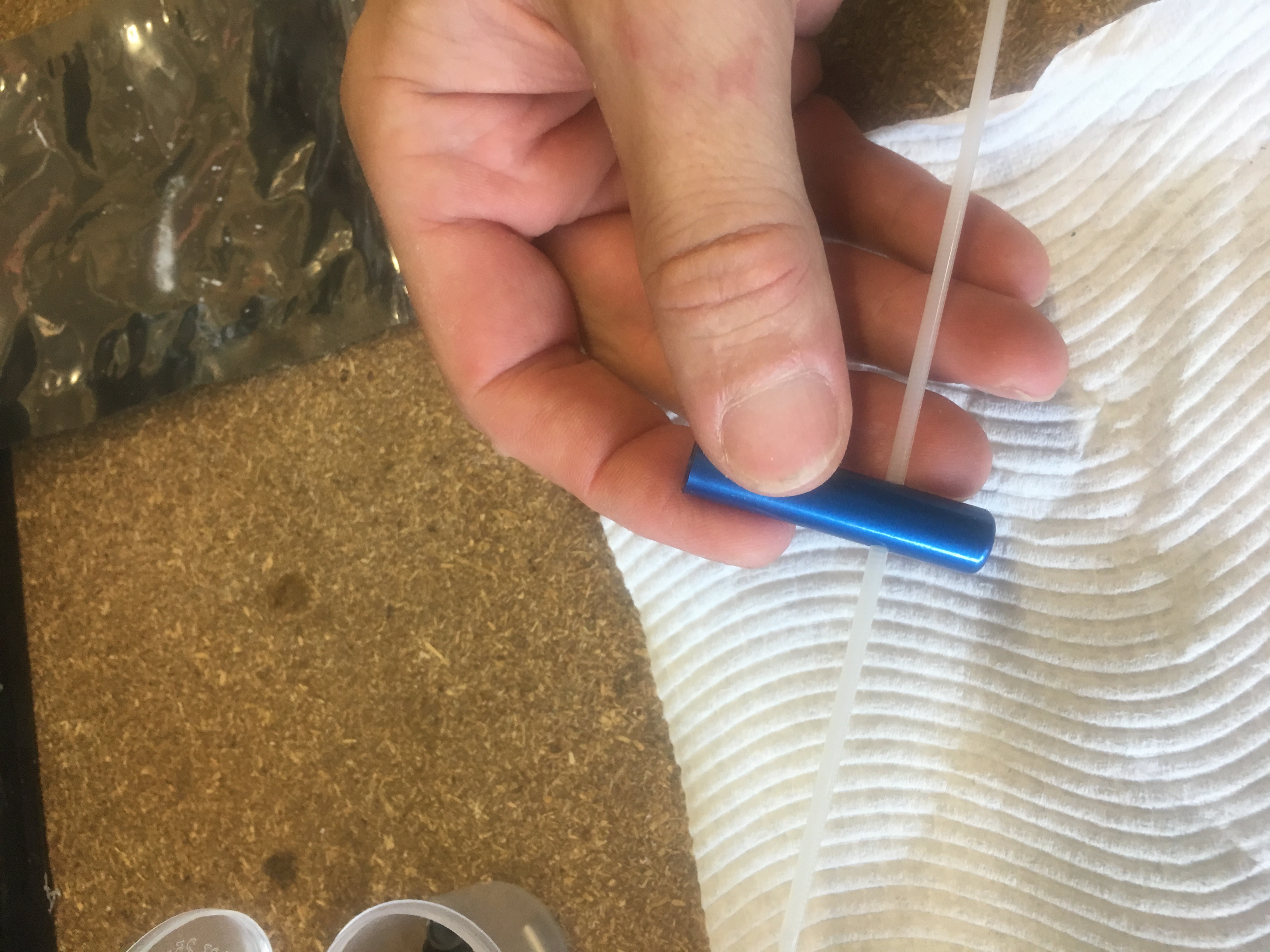
I then melted some hot glue on the end.

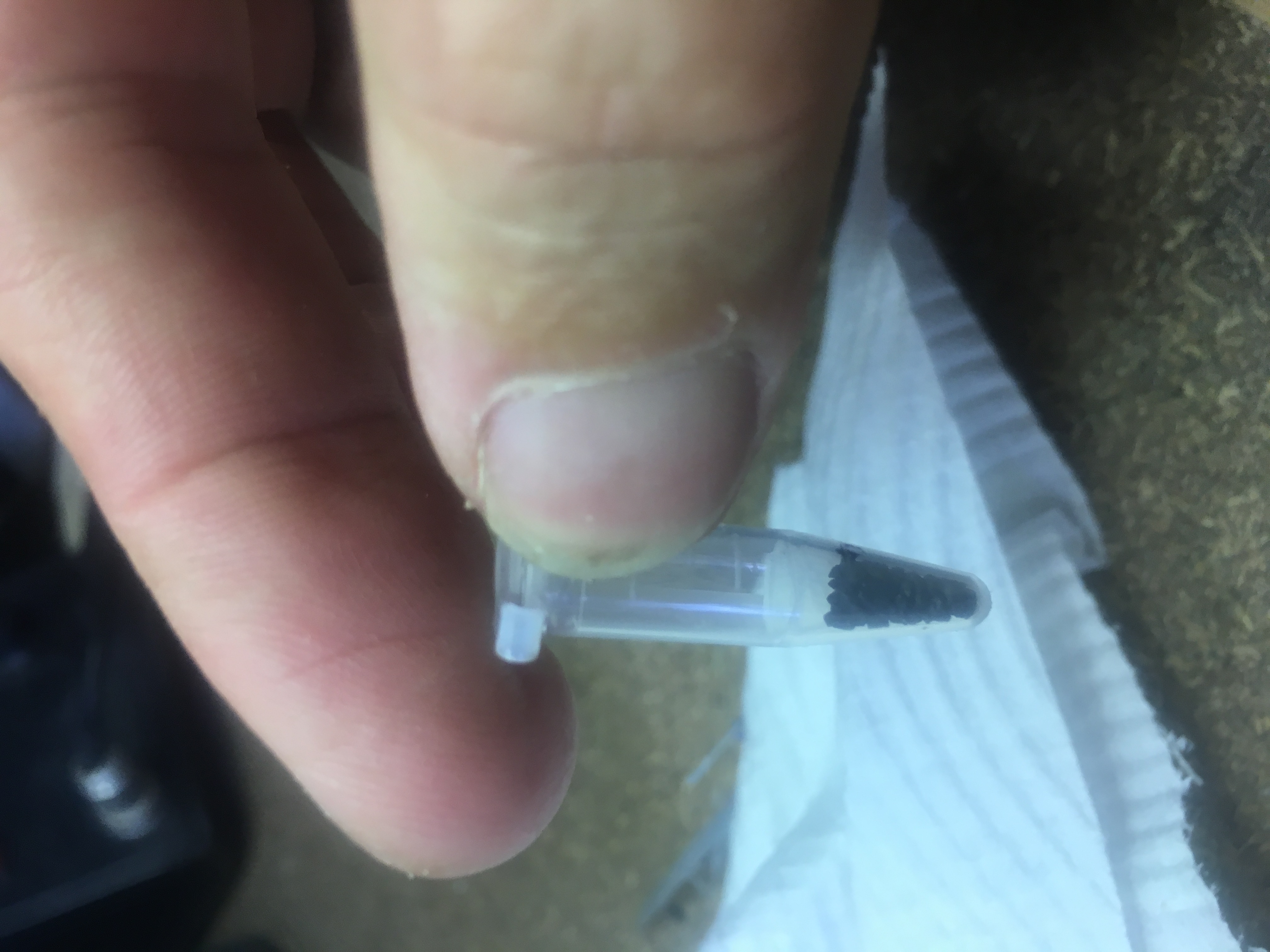
Then afterwards, I removed the screw bit…and put the measured 0.1 grams of black powder in.

0.1 grams of black powder measured.


Then I screwed it back together again.
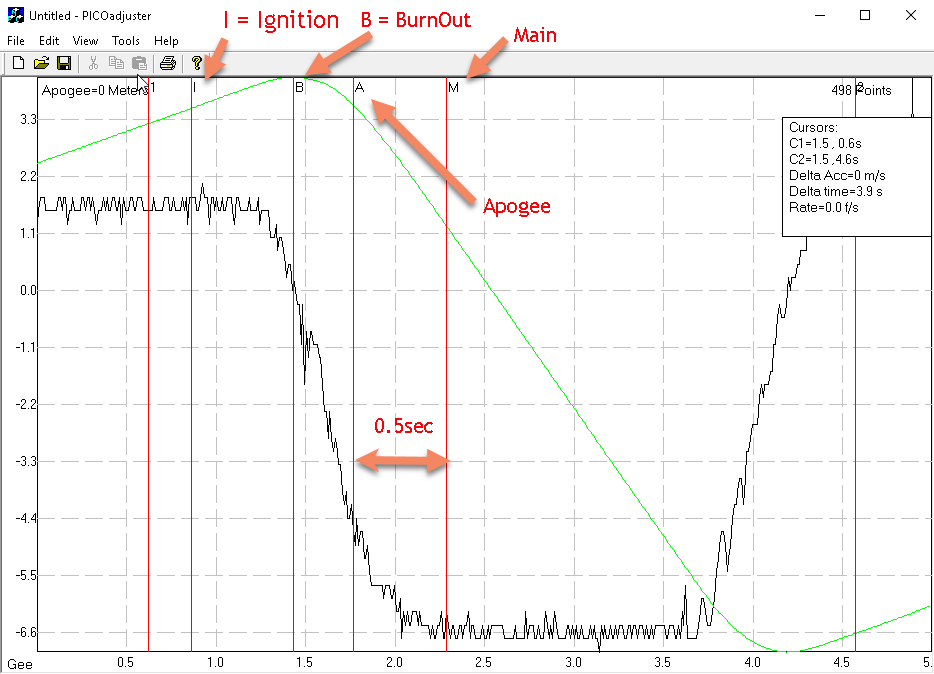
The test

Below is a video of the test.


Very happy with it!

Testing the Igniters

What I wanted to test

I am using a Pico AA2 Altimeter and I wanted to run a few tests:-

  1. Test that the Altimeter seems to work – i.e. will detect launch and can detect Burnout and then Apogee. I do this test because I wouldn’t want to fly with a faulty Altimeter
  2. Test that the Altimeter with the 2 x 3.7v 180maH LiPO batteries can supply the current required to fire two e-Matches one after the other
  3. Test the Cable Cutter and the procedure to set it up.

The Set-up

Here are photos taken during the set-up.

Igniter already threaded through cable cutter closure.
Tape put around the igniter, to reduce chance of shorting against the Cable Cutter case.
Hot Glue to keep the black powder in.
All the igniters connected.
Everything connected.


The Results

Here are the results

Detection of Launch Events

Data from "test" launch on bench
Data from “test” launch on bench

We had the Pico AA2 pointed up while it was configured with 2G = 8 which is equal to about 1/4g. Because the G’s are more than 0.25g, the Pico AA2 thinks it has detected launch.

I then turn the Pico so that it is horizontal. As I do this, the G’s pass through zero, which it takes a motor BurnOut. Then it looks at the area under the curve as the rocket “deaccelerates” and when this area is equal to area under curve between Ignition and BurnOut, it then assumes we have lost the velocity we gained; i.e. we are at Apogee. So it fires the Apogee (A) event. Then, because we are below the 800ft, it fires the Main 0.5 seconds later.


Apogee

This will ignite black powder that will separate the top section of the rocket (including the nose cone) from the main air-frame. In this test, we just want to make sure the igniter does it’s job. Ignites.


The Main

Here we test that Main Output fires.

Conclusion

So I ran this test and I’m now fairly comfortable that the Pico AA2 works. I also observed both igniters working, which means the Pico AA2 batteries can be depended upon.

However, the Cable Cutter did not fire. I suspect this is because of two things.

  1. The piston is a dud – it doesn’t have a “cutting edge” like other photos show
  2. A significant portion of the black powder gas went out the back.

Here is a photo of the piston.

This should have a very sharp cutting edge...a concave hole.
This should have a very sharp cutting edge…a concave hole.
The piston seized up in the cable cutter body. This screw-driver shows how far it was stuck in.

Trial Carbon Fibre Layup

Did a trial run doing a layup of Carbon Fibre on to G10 material on the weekend.

Layup consisted of:-
* Small piece of G10 material “roughed up” with Grit 60 sand paper,
* Two layers of CF
* Two pieces of Nylon Peel Ply
* K3600 Renlam Epoxy

The first piece of carbon fibre extended past the edge of G10 by about 15mm. The second layer was 5 mm within the edges.
I waited 5.5 hours after the layup to cut the excess off CF. It was easy to do.
Waited another 15 hours before I removed the Peel Ply. It was easy to remove the Peel Ply.

Below are some photos I took.

Weighing the G10 material


Weighing one piece of CF

So therefore the large piece of carbon fiber weights ~3 grams.


Weighing two pieces of CF

So therefore the smaller piece of carbon fiber weights ~2 grams.


Mixed up the Renlam Epoxy.


Applied a generous amount of Epoxy to the G10 plate.
Placed Carbon Fibre on to the wetted G10 plate.


Applying more epoxy to first layer of Carbon Fibre - don't want to miss any bit of it.... and Added second piece of Carbon Fibre
Applying more epoxy to first layer of Carbon Fibre – don’t want to miss any bit of it…. and Added second piece of Carbon Fibre


Wetted out the second layer of Carbon Fibre.


Applied two layers of Nylon Peel Ply
Nylon Peel Ply completely wetted out.
Added Magnetic sand (in two bags) on to the job. Then placed wood and 4kg weight on top.


5.5 hrs has passed and about to trim off excess material.
Trimmed excess quite easily/quickly with a pair of scissors.
IMG_6014
Used a sharp knife to initiate removal of Peel Ply ~24hrs after starting Lay up.
Completely finished Lay up! (except for the finish itself)

Final Weight: 44 grams

This means the Epoxy weight was approximately:  2 grams

So the total weight of the epoxy/CF is 3 + 2 + 2 = 7 grams. Very light!

The carbon fibre seems to have bonded well with the G10 material. The resultant piece is a lot stiffer.

My next step (if this was the real fin) would be to apply a very thing coat of K3600 and then sand with progressively higher grits.

Now considering a real fin layup this weekend.

Testing out the Ejection charges

I purchased the following eMatches to test out the ejection charges.

https://ausrocketry.com.au/igniters-e-matches/j-tek-lf-electric-match-24-inch-60cm-1.html

The recommended firing current is 1 Amp. The Duracell battery I want to use should be able to supply this without any trouble. I wish to conduct three tests:-

  • Test 1 – firing igniter standalone
  • Test 2 – Fire igniters from the Raven 3
  • Test 3 – Ejection test of drogue parachute.
  • Test 4 – Ejection test of main parachute.

To perform all these tests I created a test-fire box using old Cat-5 cable and some old parts lying around. Here is a movie describing what I made.

It isn’t neat/tidy, but very functional and safe. I can install all deployment charges without having the battery connected at all.

Test 1

I wanted to convince myself that the igniter would work on one of these nine volt batteries with this ignition system. Below is a video showing this.


The remaining tests will come in other posts.

Testing out the Stabilisation System

I’ve created a jig (from 3-D Printout and some wood) into which we can mount the Stabilisation system and have it connected to the computer and to either an internal or external PSU for the Servo Motors. This set-up is good, because it allows me to easily update the Arduino program as I find bugs or worthwhile enhancements.

Below is a video a recent test.


In the first ~4 seconds, it shows me lifting (accelerating) the system up. You will notice that the red turns off. This marks the time that the rocket has sensed sufficient acceleration for it to assume the rocket has been launched.

Then we see after a very short period (0.1 seconds in real time), the red LED turns on. This marks the time the rocket circuitry has decided that it should move the masses. You see them moving very quickly to the front.

Then as the movie continues (in normal speed), you see me rotating the rocket, but the masses continue to maintain their ‘direction’. This is to ensure that the moment generated by the rocket motor stays in the same direction.

It has been estimated that in a state of minimal air resistance this would lead to an angle of ~ 14 degrees. Of course, there will be air resistance and this experimental launch will give us an indication of the ‘real’ amount it affects the motion of the rocket. This is very important for us in the tuning of the stabilisation system.


I’ve created a Java 3D simulation of this rocket during the motor firing.


This is for a Callisto rocket with a 125G131-14A (SS) motor. It’s final motion properties are:-

  • Rotational Velocity: 32 degrees/second
  • Rotational Position: 14 degrees from the vertical
  • Down-Stream Position: 1.25 metres
  • Down-Stream Velocity: 6.5 metres/second

We can determine that that the masses are moved to their position 2 frames later, so the total number of frames passed by time masses are moved is 5.  This equates to approximately 0.21 seconds.

We are interested to know is what the velocity and position is when this starts. We want it to be when stabilisation has occurred, but we also want as much time as possible in this position, so we can maximum amount of data.


NOTE: I am aware that the moment generated is a result of ALL the forces on the rocket cross product with the distance vector and I’m obviously ignoring a non-trivial force, the aerodynamic forces. It is expected however that we should see some tenancy for the rocket to veer to one side. The results will be interesting and useful.

It is expected that shortly after the rocket motor has finished, the rocket still stabilise and not rotate much more.  This is because aerodynamic forces will provide counter-acting Moment.