38mm CTI and AeroPak motors come buy default with approx 1.4 grams of Black Powder for their ejection charges. Based on this and the fact my rocket has half of volume blocked off by engine block, I decided to start my ejection charge tests at 0.75 grams. Ultimately I got up to 1.76 grams of BP. This post discusses this in detail.
How the system is packed.
This is probably the best place to describe how the recovery system was packed, because the tests identified a possible issue with the set-up.
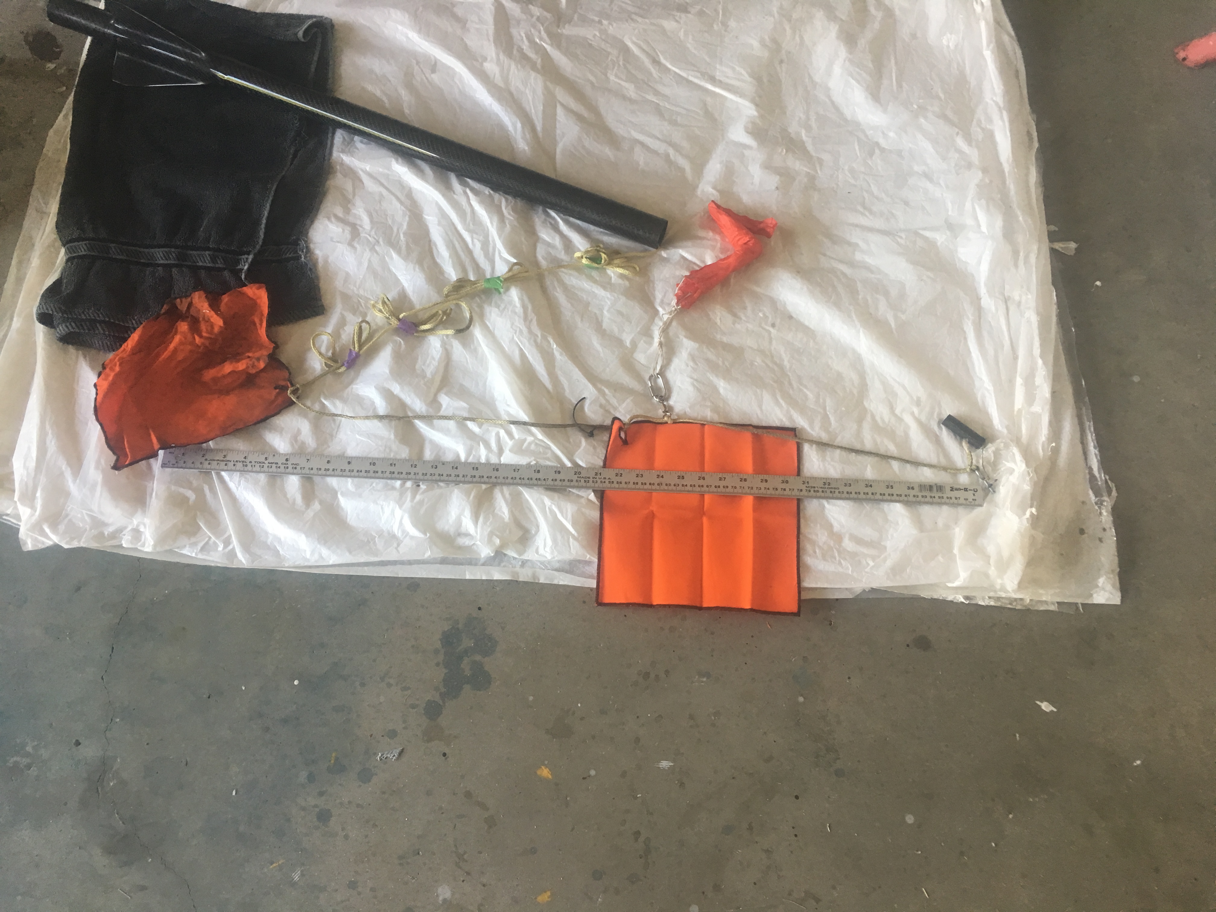
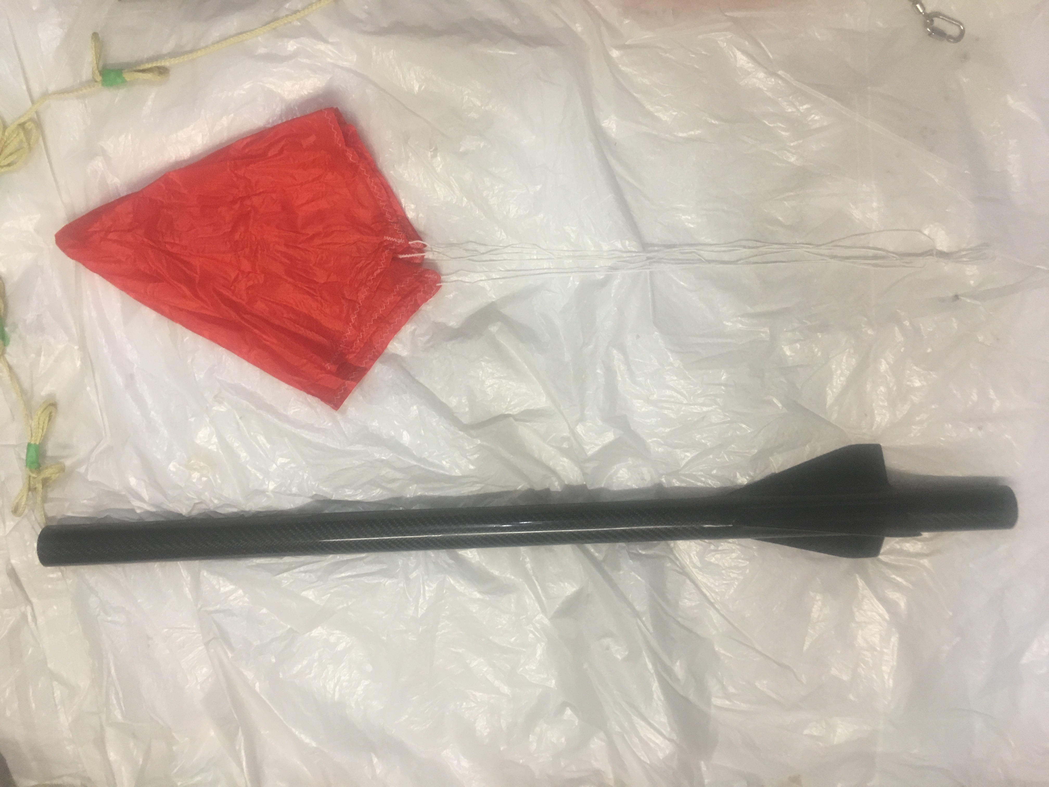
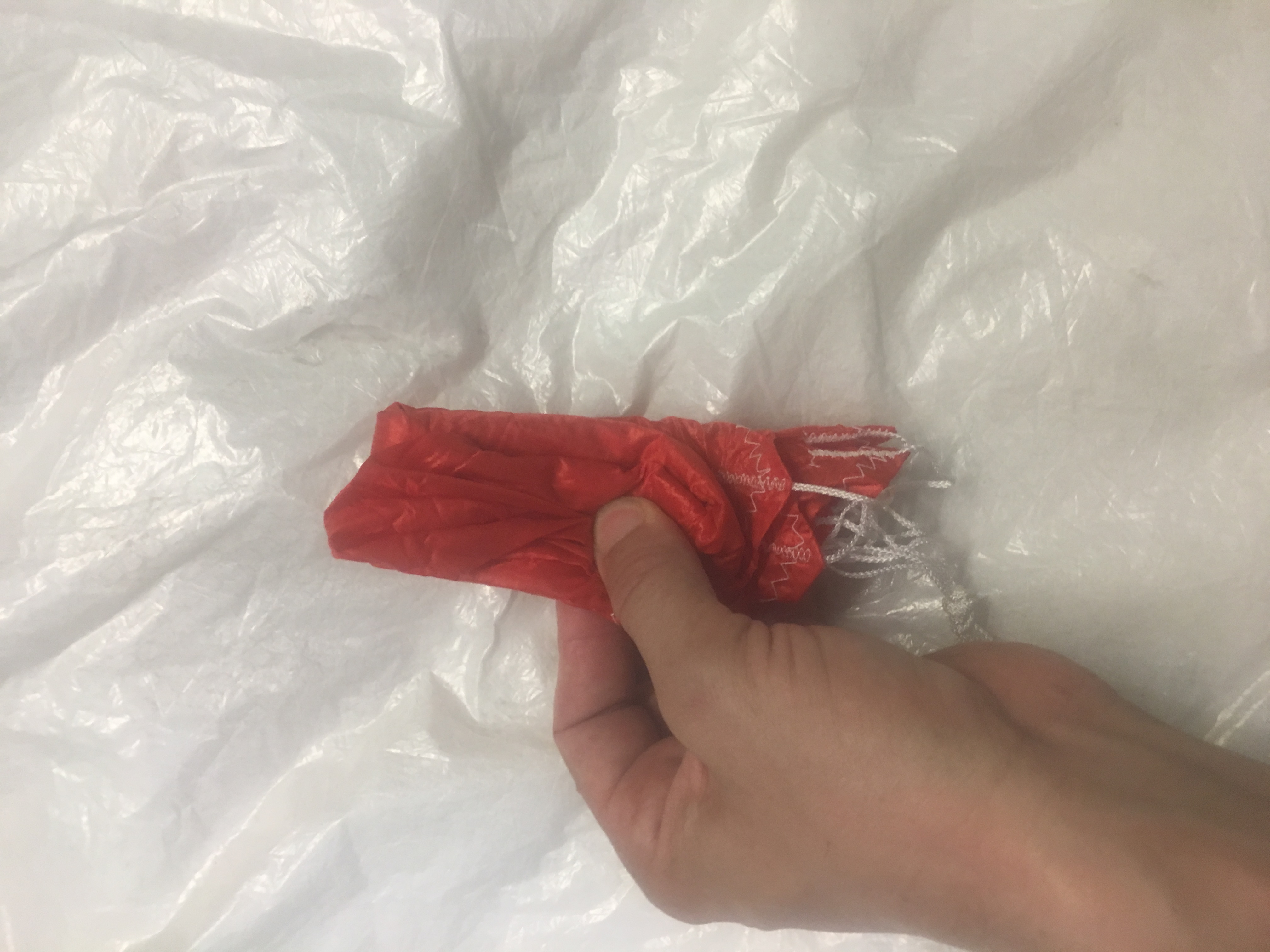
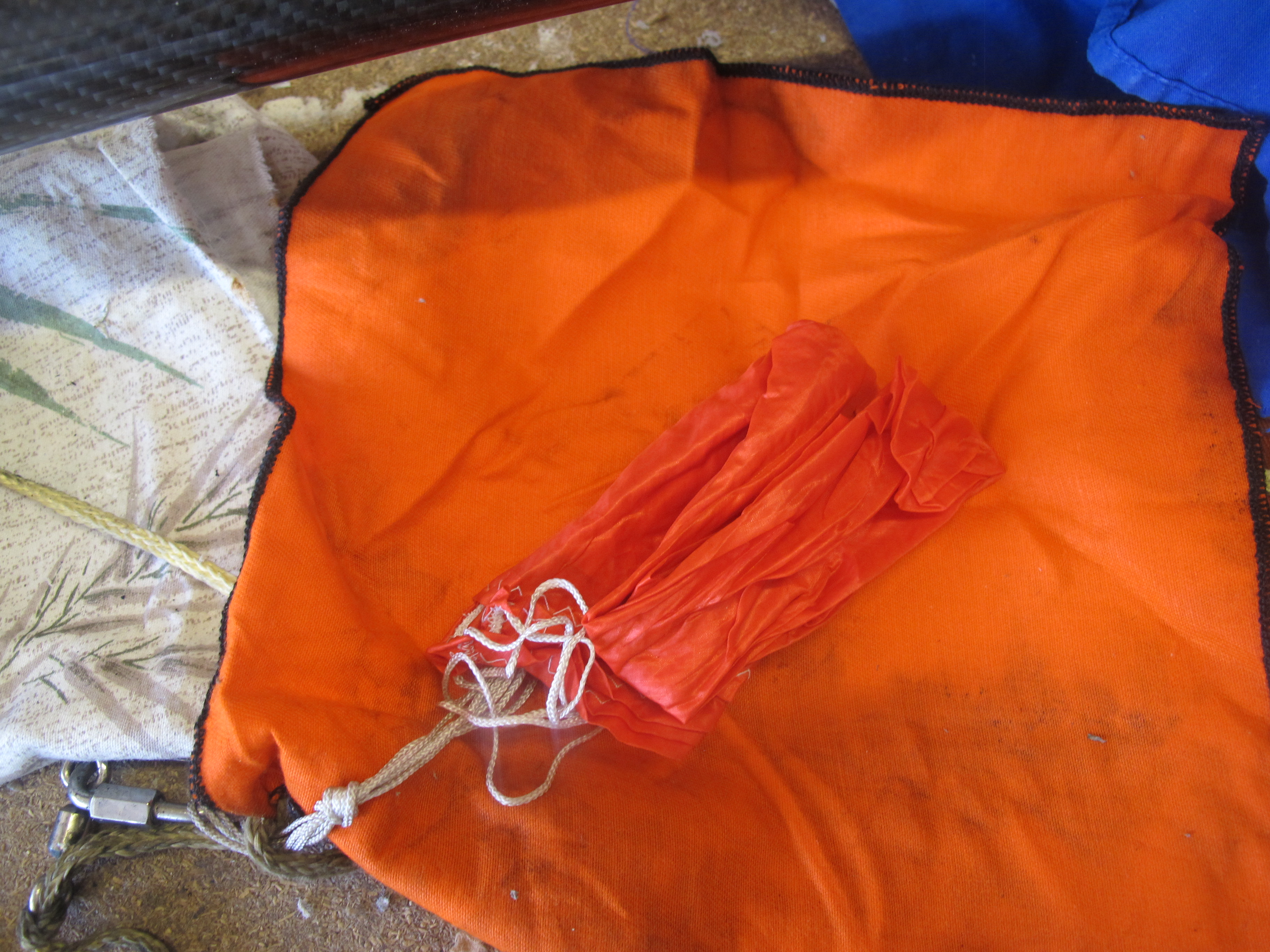
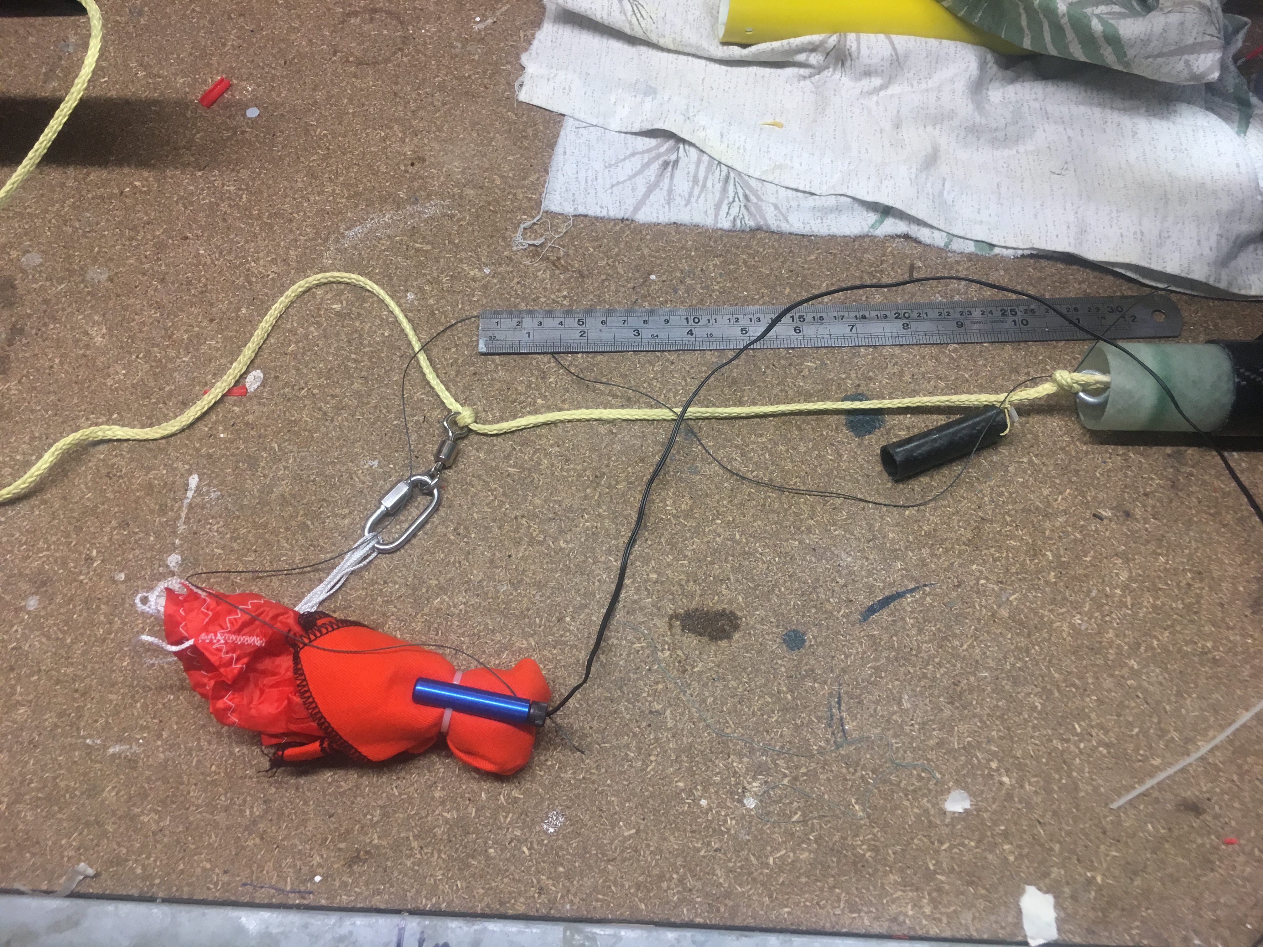
View of all the components to be packed into air-frame – prior to folding and attaching igniters, cable cutter.
You will notice in this photo there are TWO Nomex blankets. The left one covers the shock-cord (but its primary purpose is add additional drag) and the other Nomex blank protects the parachute. The right Nomex blanket is held in place with a Cable Cutter, the right is simply wrapped into a bundle.
The parachute is on a Swivel and uses a 4mm Quick-Link. The Shock-cord is 5 metres in length, with 0.5 meters inside the air-frame. Notice the use of Z-Folds.
How the Parachute is folded
Here are some photos of how it was folded.
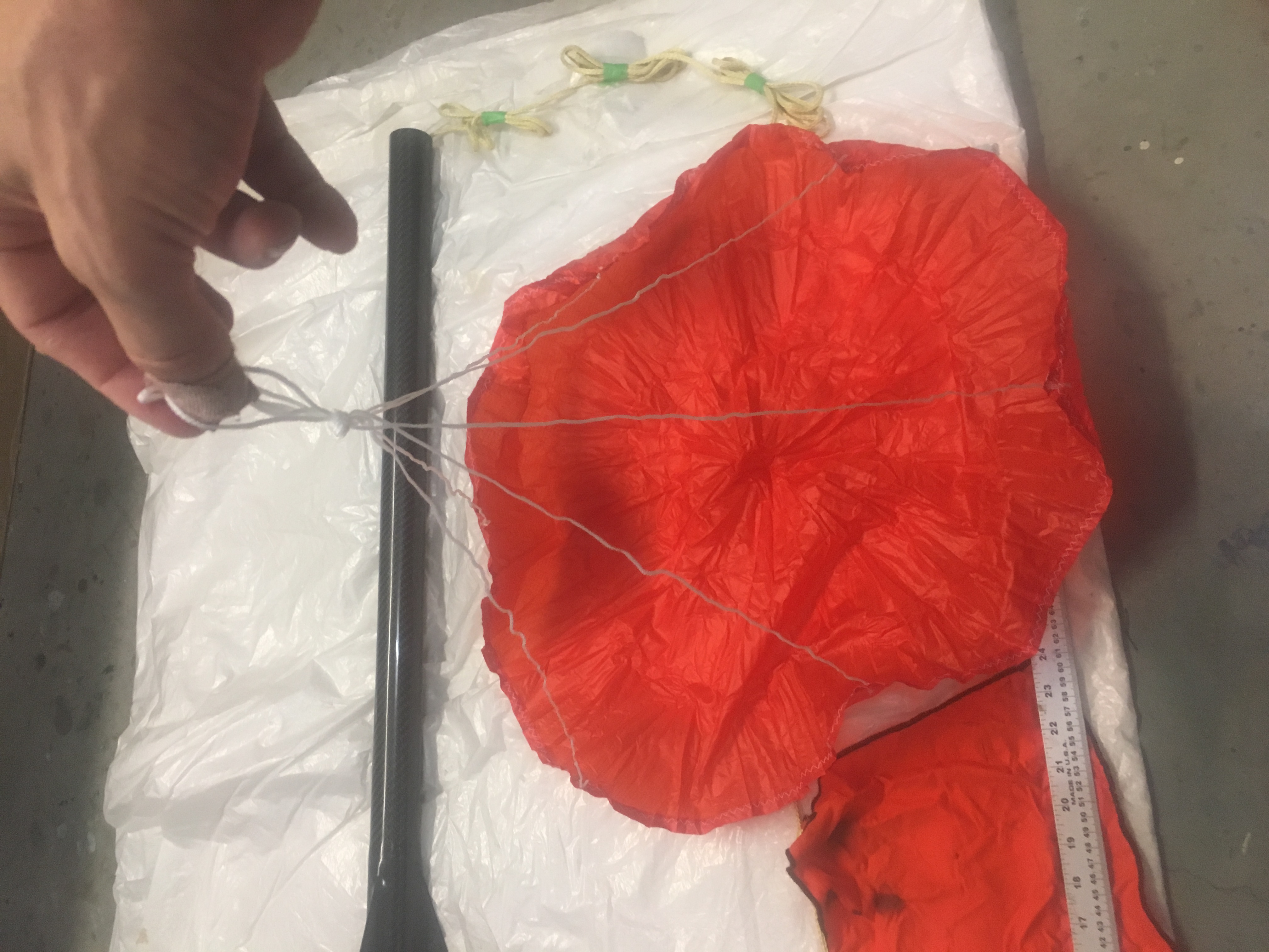
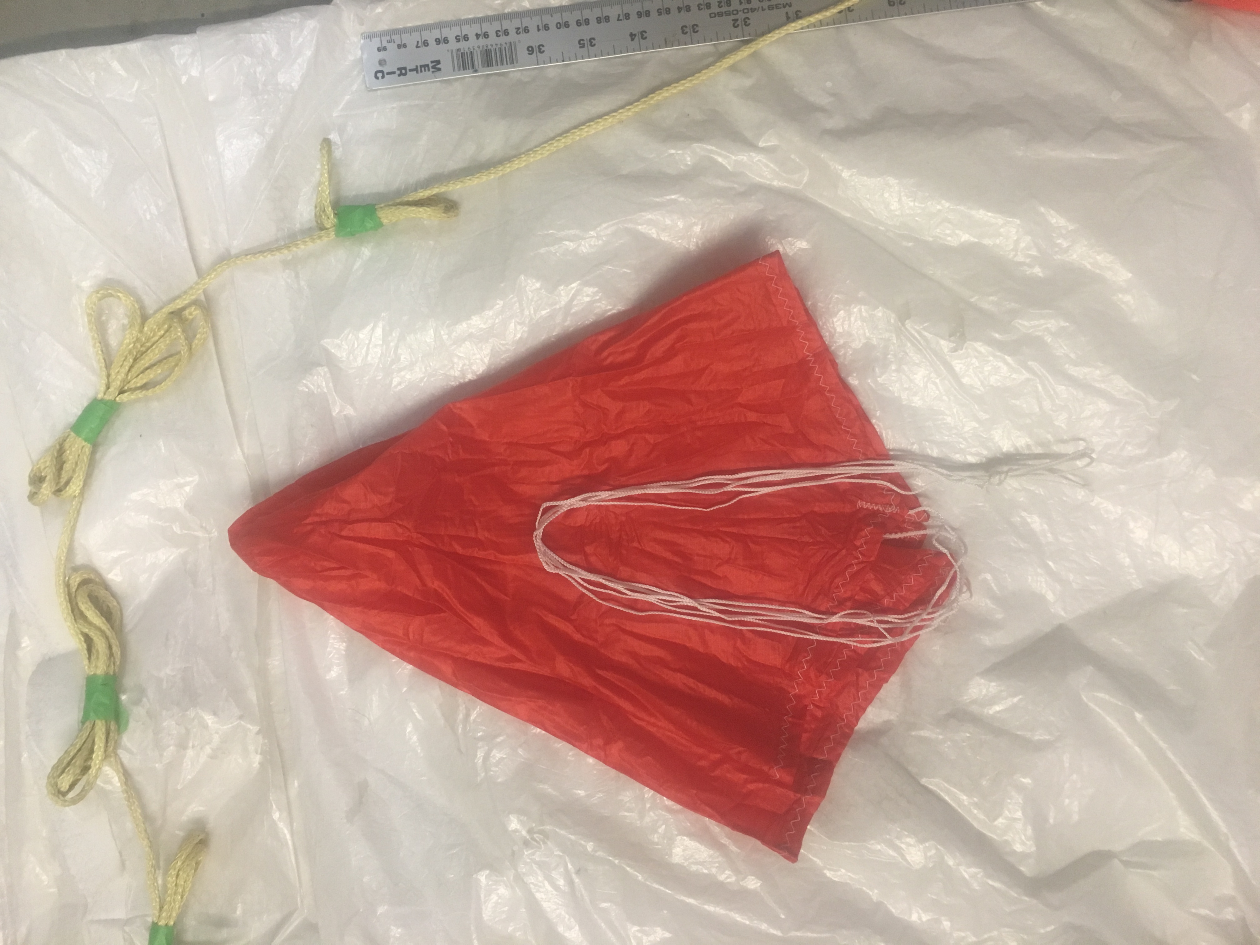
Making sure parachute has no damage and shroud lines are not tangled.Laying out the parachute, shroud lines taut.
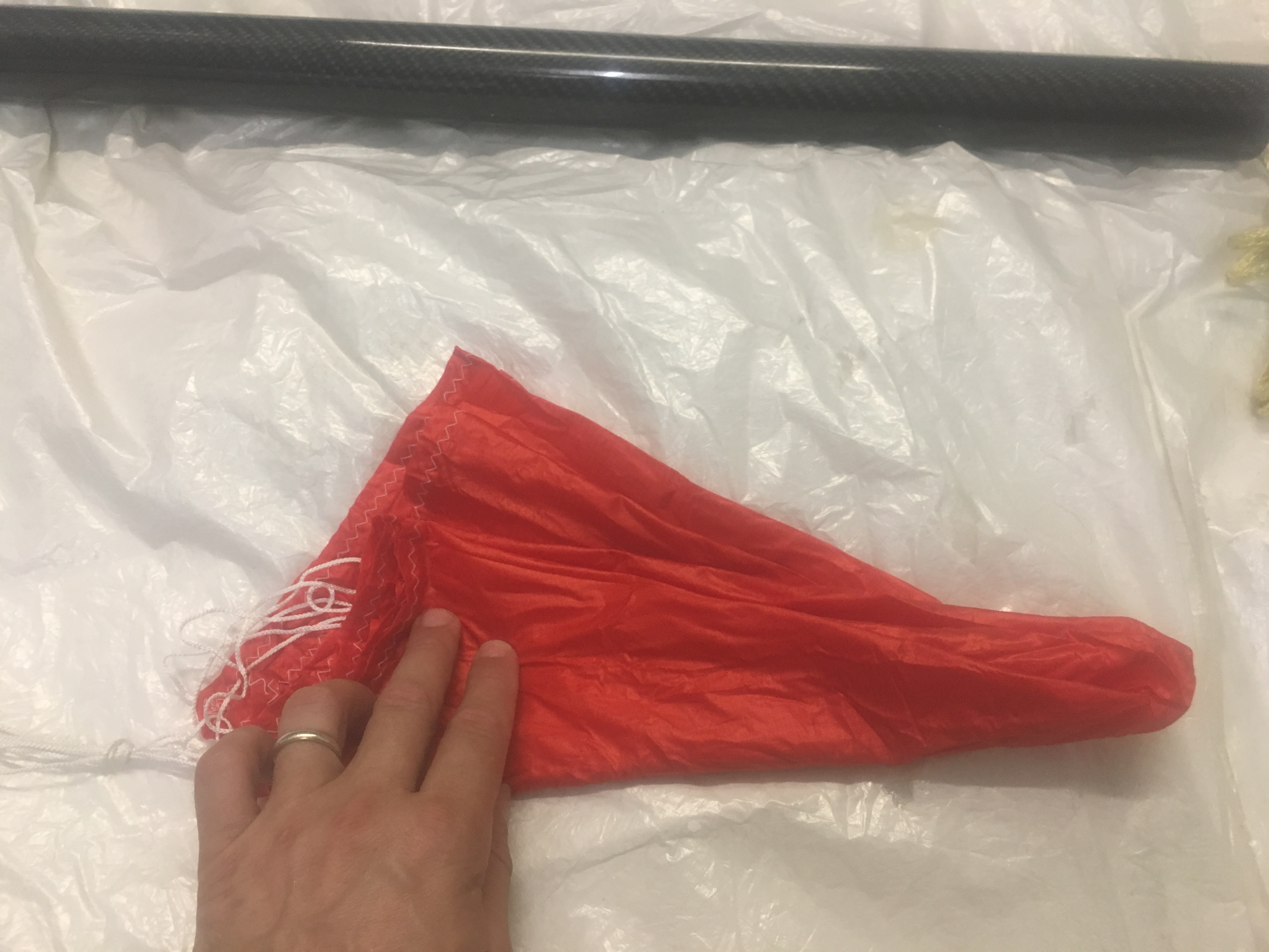
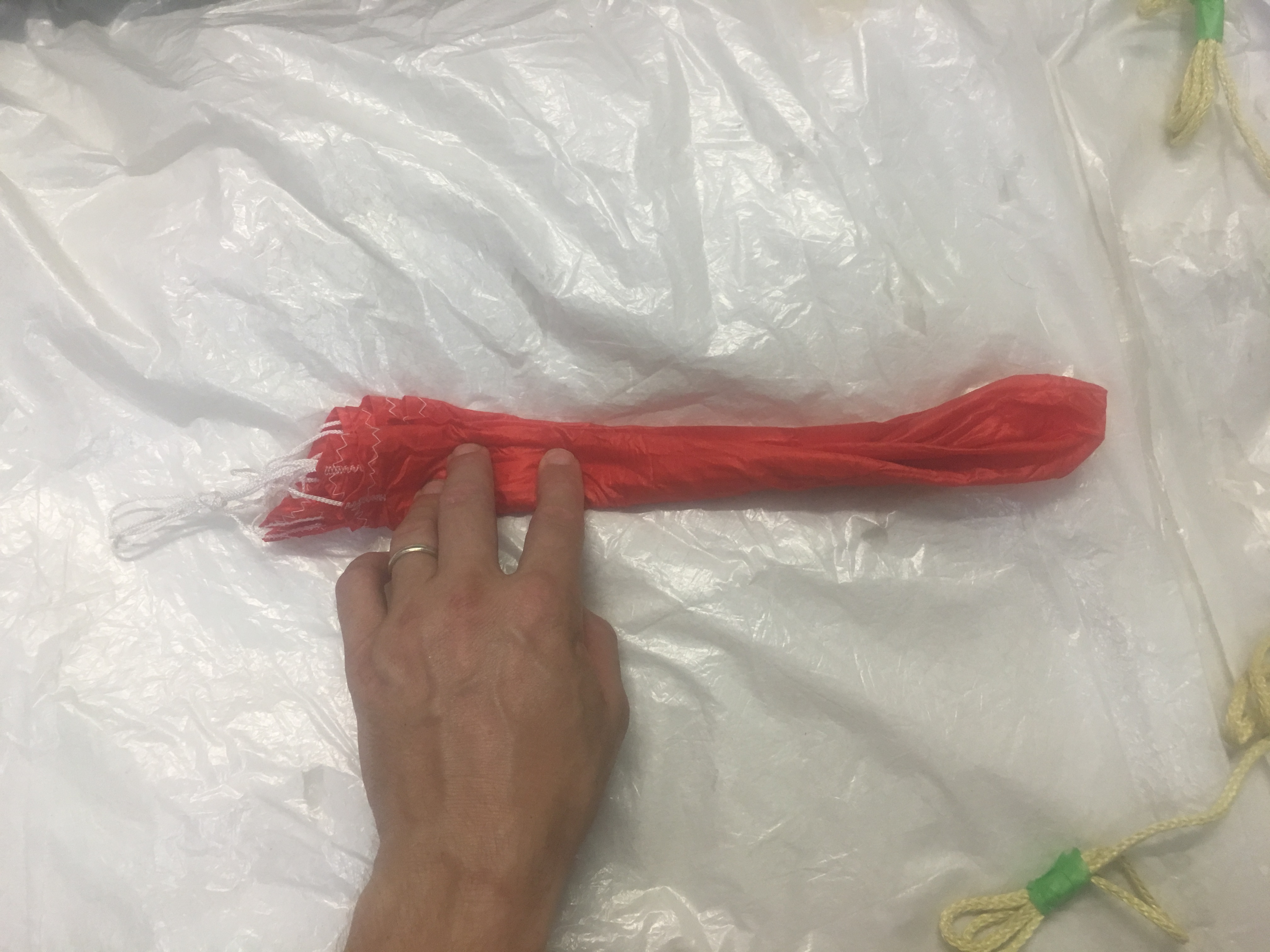
Making sure all the parachute gores are equally aligned and neat.Ensuring all gores are split evenly on each side of the shroud lines.Putting most of shroud lines about 3/4 up the parachute skirt.Folding bottom “third” up….and then top third down.Folding over again.z-folding into three.
Protecting Parachute with Nomex Blanket
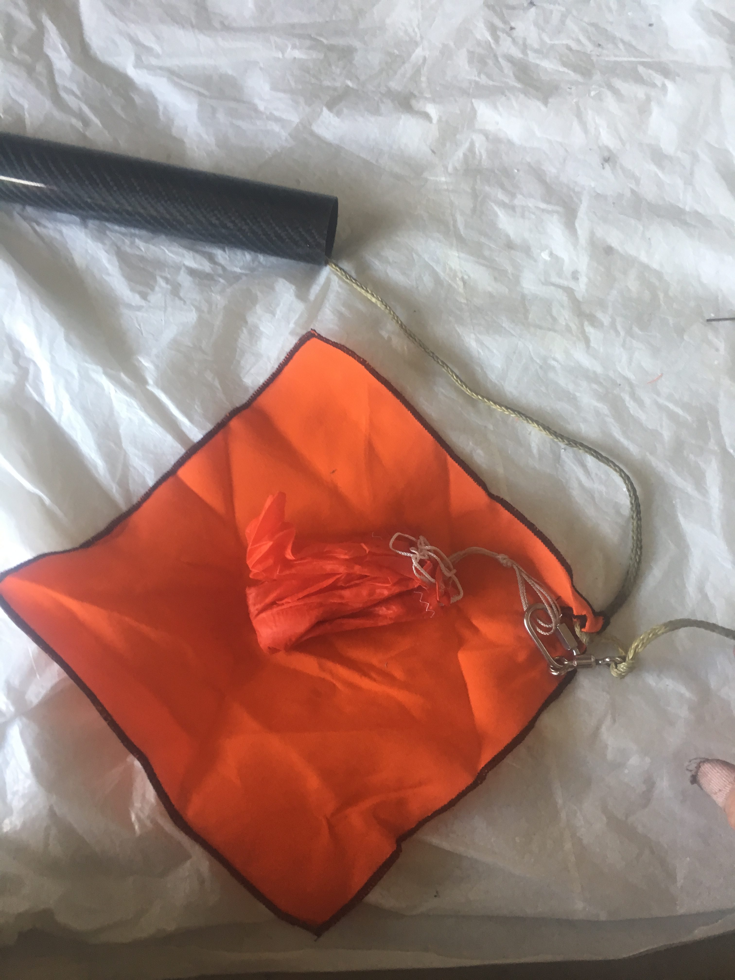
Place bundle in the centre of the Nomex blanket, with the shroud lines pointing to the right. Make sure the quick link is just outside the bundle.
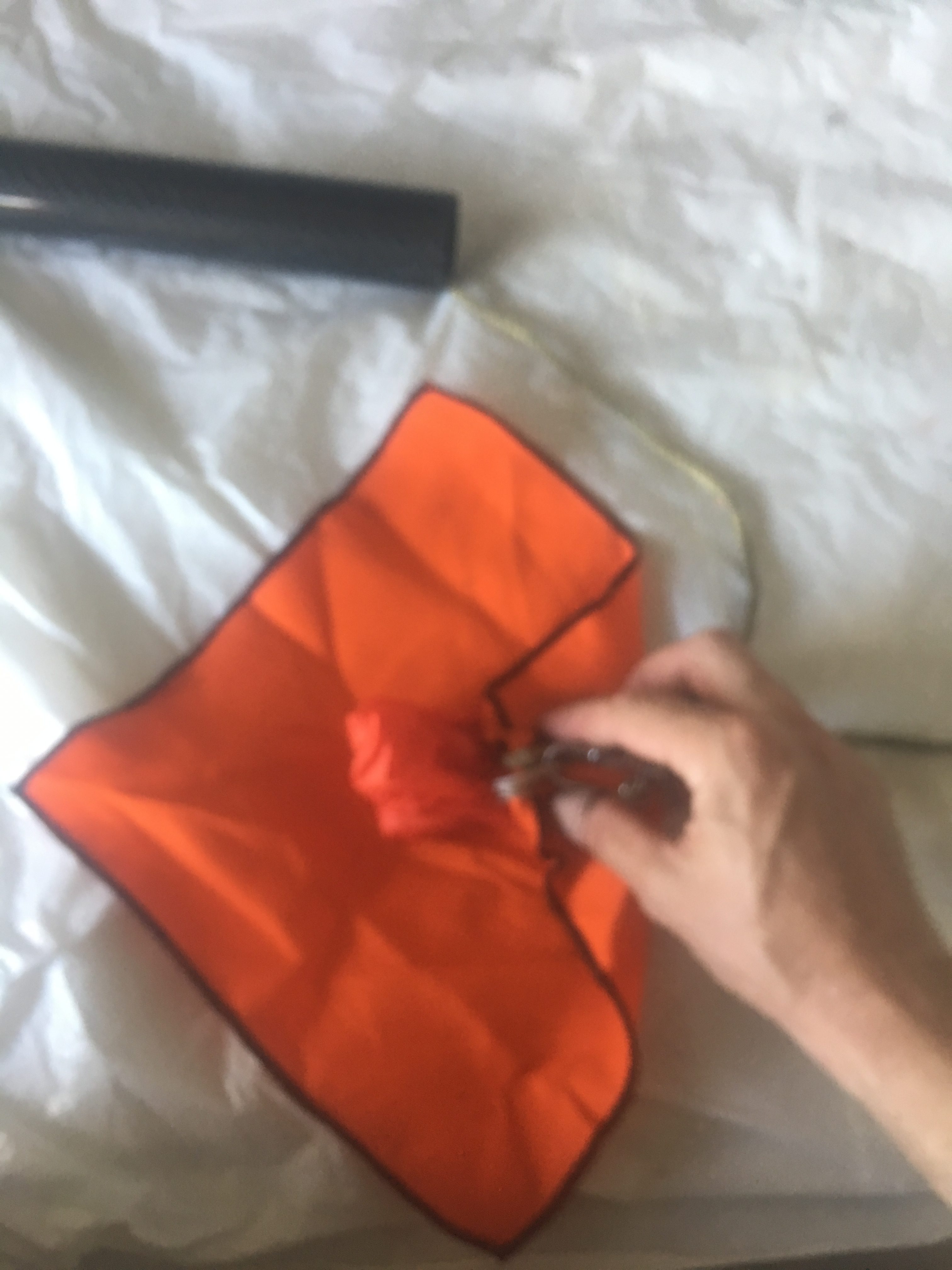
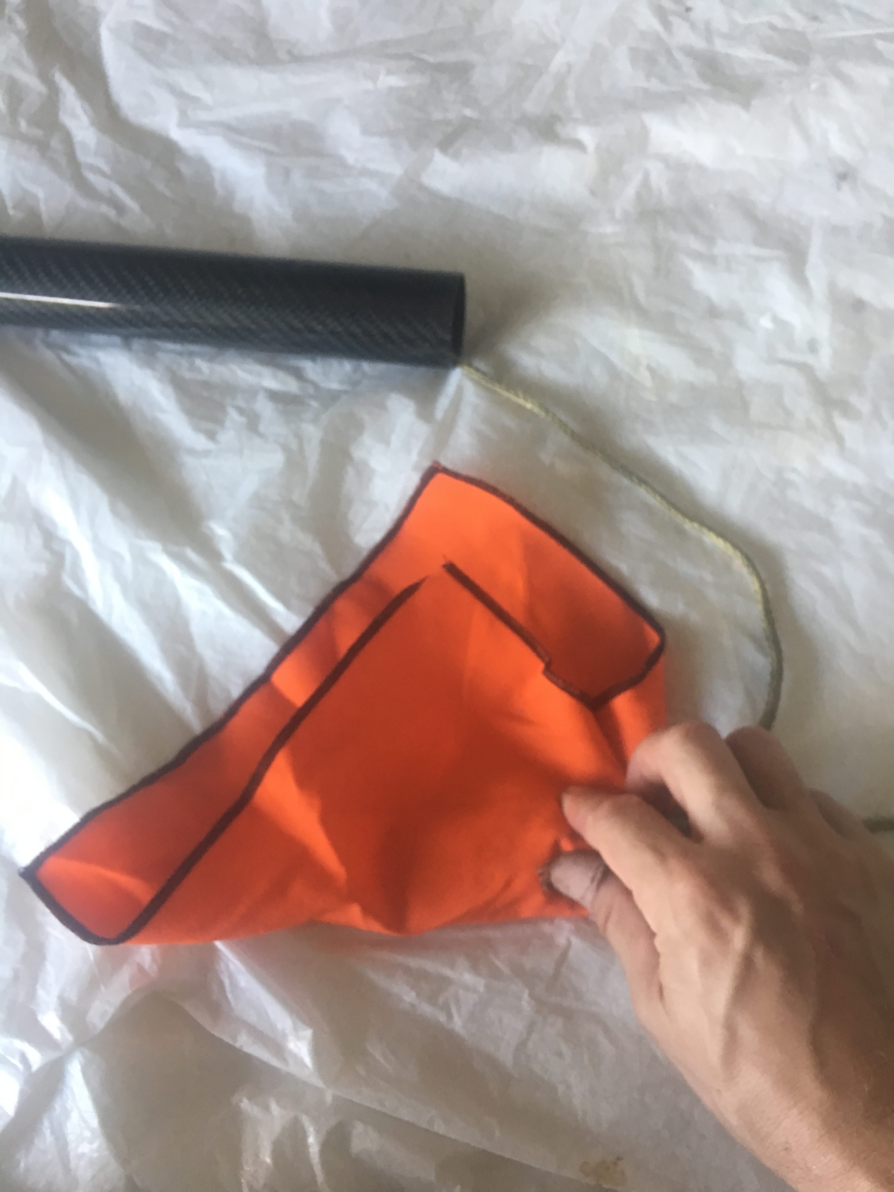
Pardon for lack of focus. Fold from RHS to about 1/3 way left.Fold bottom upFold Left piece to the right. The tightly role up.Place the Cable Cutter/cable Tie around it. Make sure the screw/end is at shroud end.
I made double sure that the parachute was attached to the shock-cord and the quick link was taped up.
Loading the recovery systems into the Air-frame.
Here are some photos of how I did it.
3rd test: Checking that there is chance of cable cutter migrating further away from the nose cone.3rd Test: Measuring length of igniter for Black Powder Charge well. Should be about 27cm.Determining any potential issues with igniters/charge well/shock cord.3rd Test: Tape igniter cable to shock cord, at two points with painting tape. Just trying to keep things orderly.3rd Test: Packing parachute bundle into air-frame.
Results of the Ejection Test
After the test we observed:-
No tangles. Great!
One of the Z-folds opened up, two left to open up (This is good). The reason this is good is because we expect the load to be “fairly” significant when the parachute inflates and these Z-folds will help reduce load on the rocket components.
There was no damage to any component (though the charge well is showing some wear after three tests. It is still in good enough condition for use in launches.
The Cable Cutter still attached to the parachute
The e-match wiring in-tact
Here are some photos and a movie.
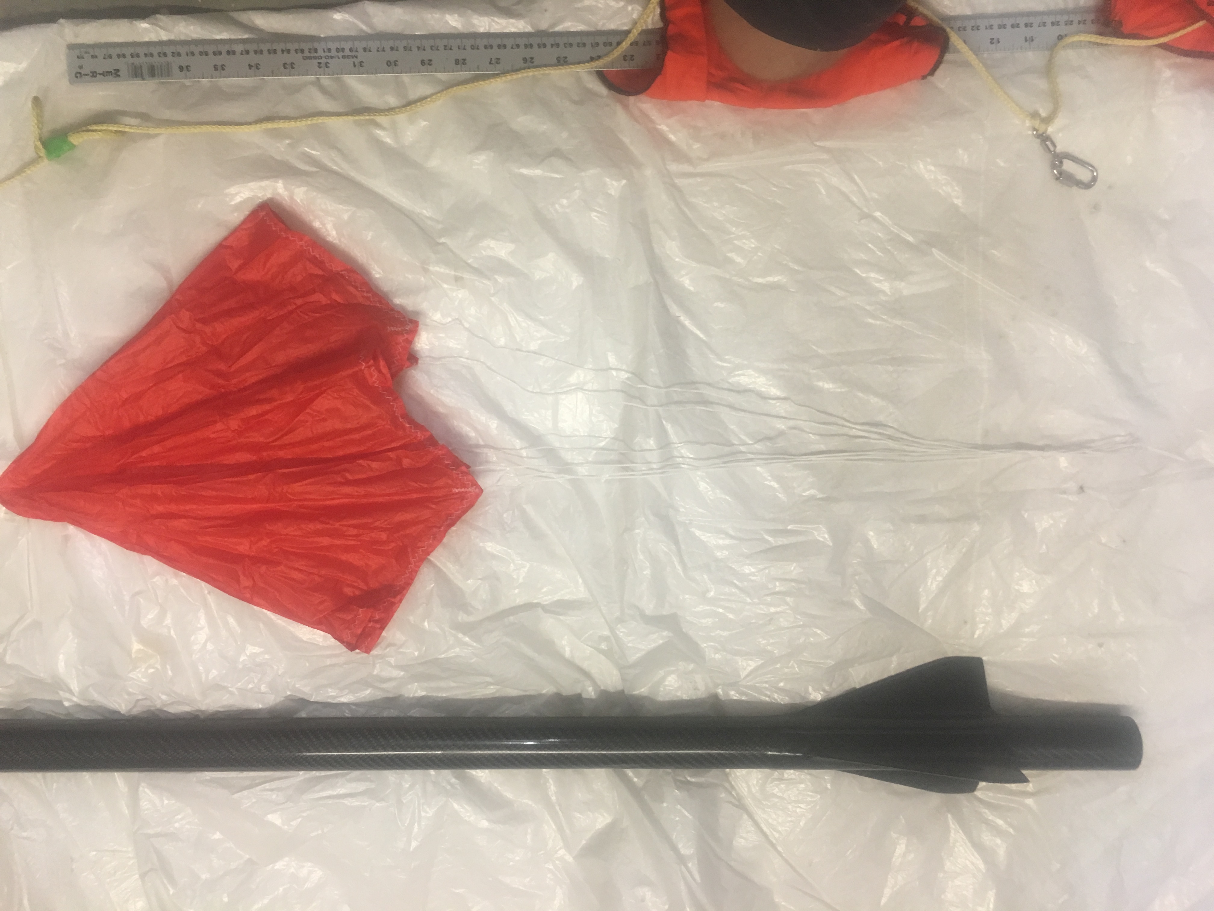
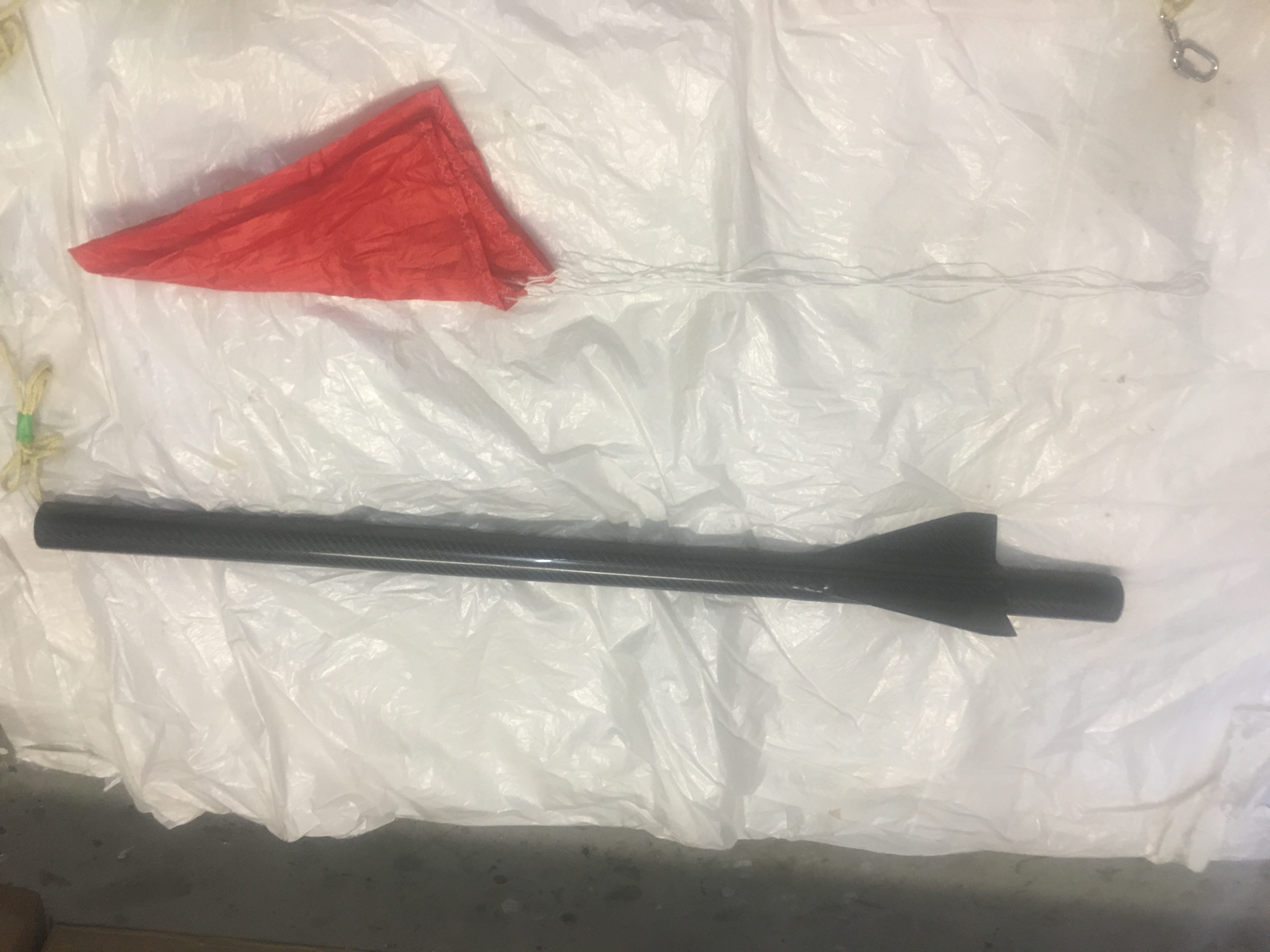
Showing off parts after ejection – side view. Take note of ruler.Inspection reveals no issues.Inspection reveals no issues.Inspection of nose cone end reveals no damage and cable cutter igniter intact. No tangles.Inspecting Cable Cutter and parachute/Nomex blanket. Seems to be intact.Inspecting parachute – no damage.
I decided to create a radio tracker for this rocket as I expect that it to travel quite far and high when it has the “real” large motors installed in it.
The Parts List
Arduino Pro Mini – 5 volt version
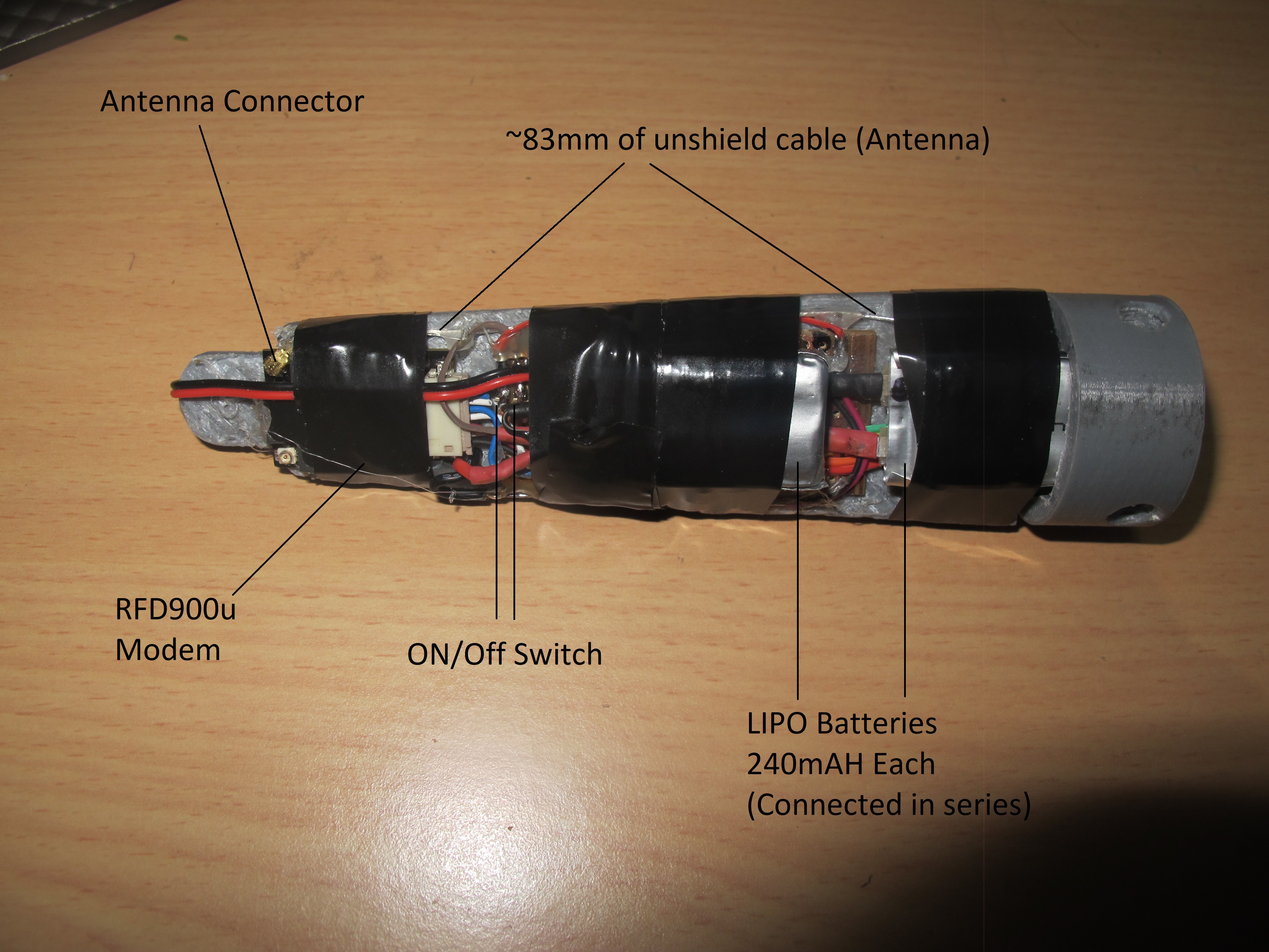
RFD900u modem
AdaFruit Ultimate GPS
3 Amp/5 volt UBEC
3-D printed “tray” to fit into the nose cone
Veraboard + header pins + wire
2 x 240mA LIPO batteries
The Design
The RFD900u modem
I connect the RFD900U modem on the rocket end to the Arduino – pins 4,5 and use Software Serial. I power the modem directly off the 5 volts from the UBEC as the power requirements of the RFD900u modem can exceed the maximum current the Arduino can supply.
I’ve loaded the modem with latest version of firmware 1.13 and after setting to the default settings I changed:-
ECC to on
TXPower to 17
I set the TXPower to 17 because life of the batteries is a big factor and 20 will suck the batteries dry. Tests have shown that every minute of operation, the batteries drop by 0.01 volts. So if the starting voltage is 8.30 volts and the final finish voltage is 7.5 volts, then we are looking at about 80 mins of operation. This is fine.
One of the issues I had was working out the antenna side of things. There is just not enough space to cram a 1/2 dipole antenna. So I have to go for a 1/4 dipole antenna. unfortunately, there really isn’t enough space for this either!! So I converted a cable for connecting an antenna INTO the antenna!
The Ultimate GPS
This device is connected to pins 2, 3. It chews about 20mA of power and is also powered directly from UBEC.
I’ve written the Arduino program to log GPS points to the internal logging area. Unfortunately, it only logs it every 15 seconds. That will have to do.
The Arduino Controller
There isn’t much to this. I choose to use a 5-volt version because all devices I’m connecting to it can operate at 5 volts. This controller doesn’t have much work to do. All it needs to do is read GPS data and send it to the Receiver via the RFD900u.
The mounting tray
I wanted to mount this inside the fibre-glass nose cone. This was quite tricky because of the limited space. One thing I wanted was for the tray to follow the contours of the inside of the nose cone. i.e. rub up against it. This will provide some stability in flight. It will also maximise area for mounting the components.
Construction
Here are some photos:-
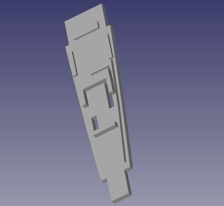
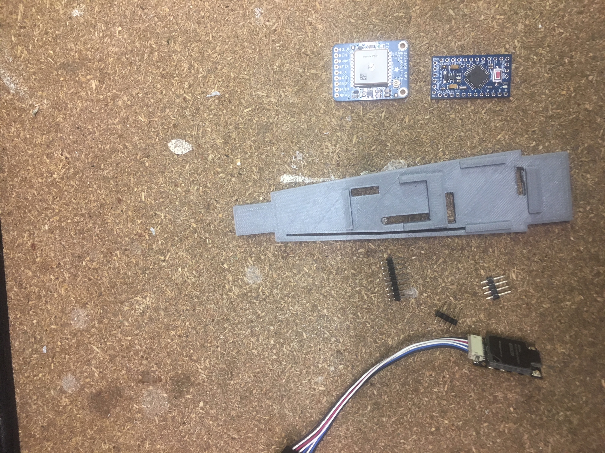
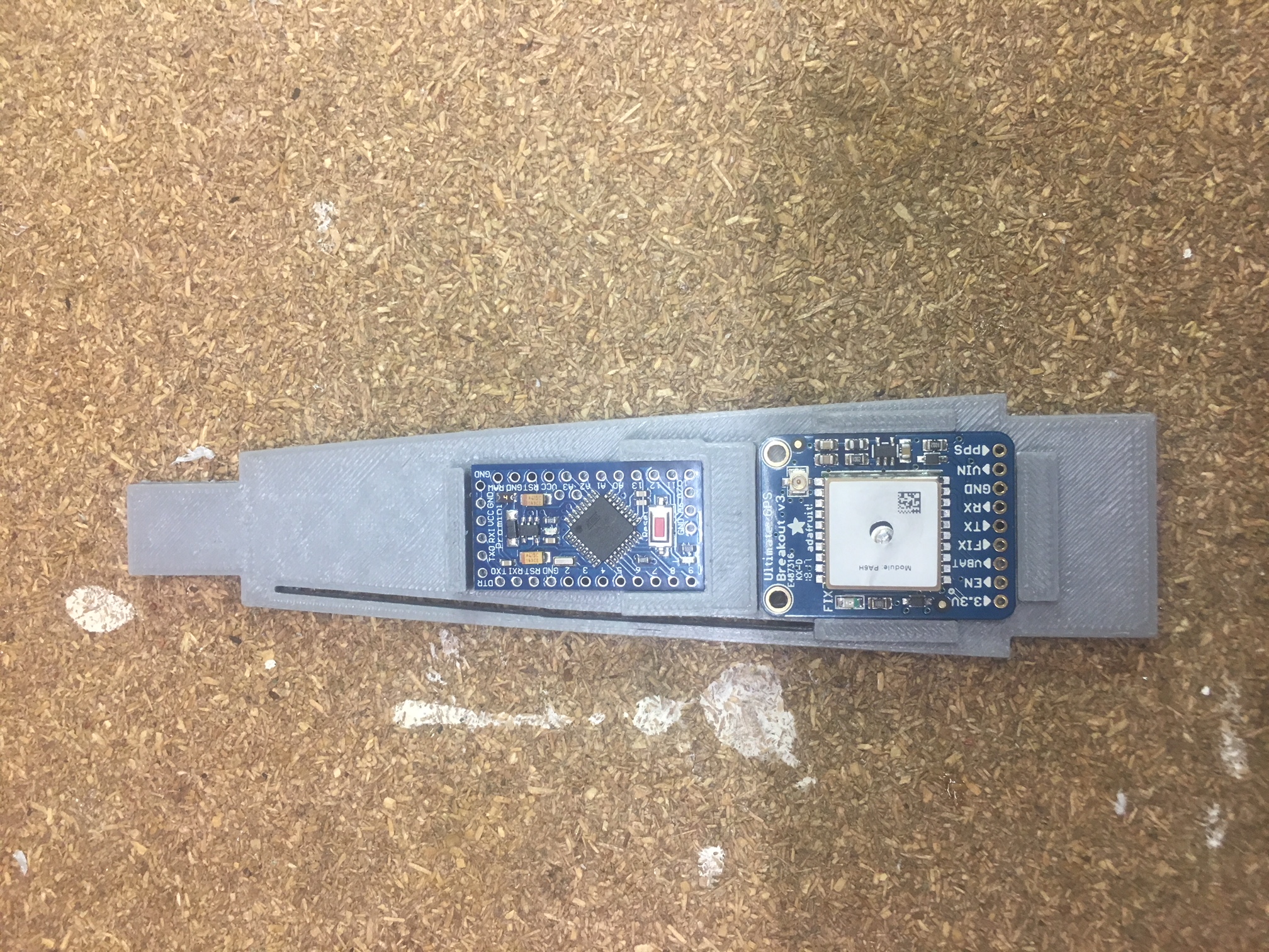
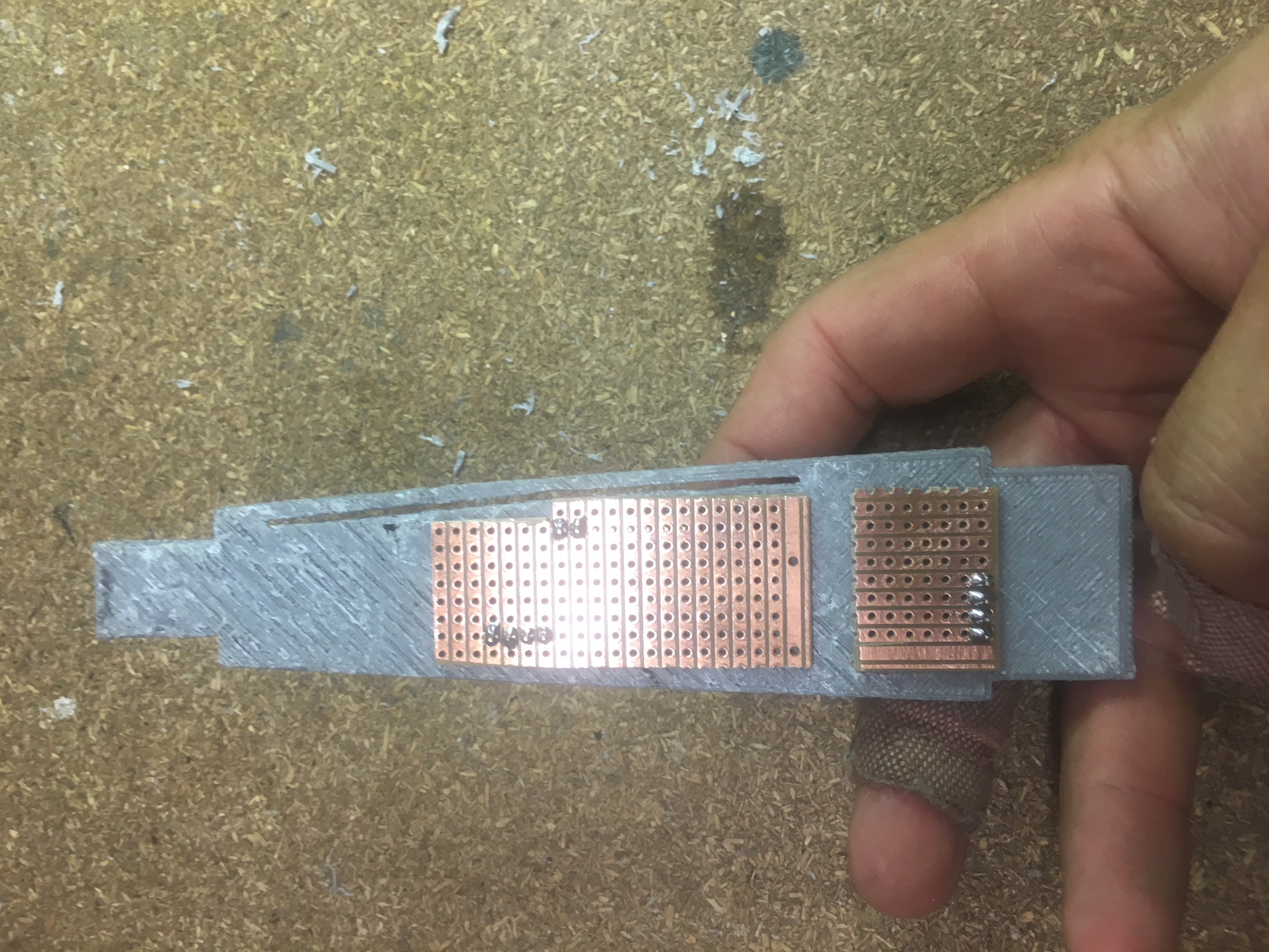
Screen grab from FreeCad.All parts out ready for assembly.Electronics Breakout Board side
Vera board side.Assembled in cylinder section that slides into the coupler.
I dislike Hot-Glue, but It came in handy for attaching:-
RFD900U modem
2 x LIPO batteries
Keeping wires “safe”
Ensuring GPS and Arduino module can’t pop out.
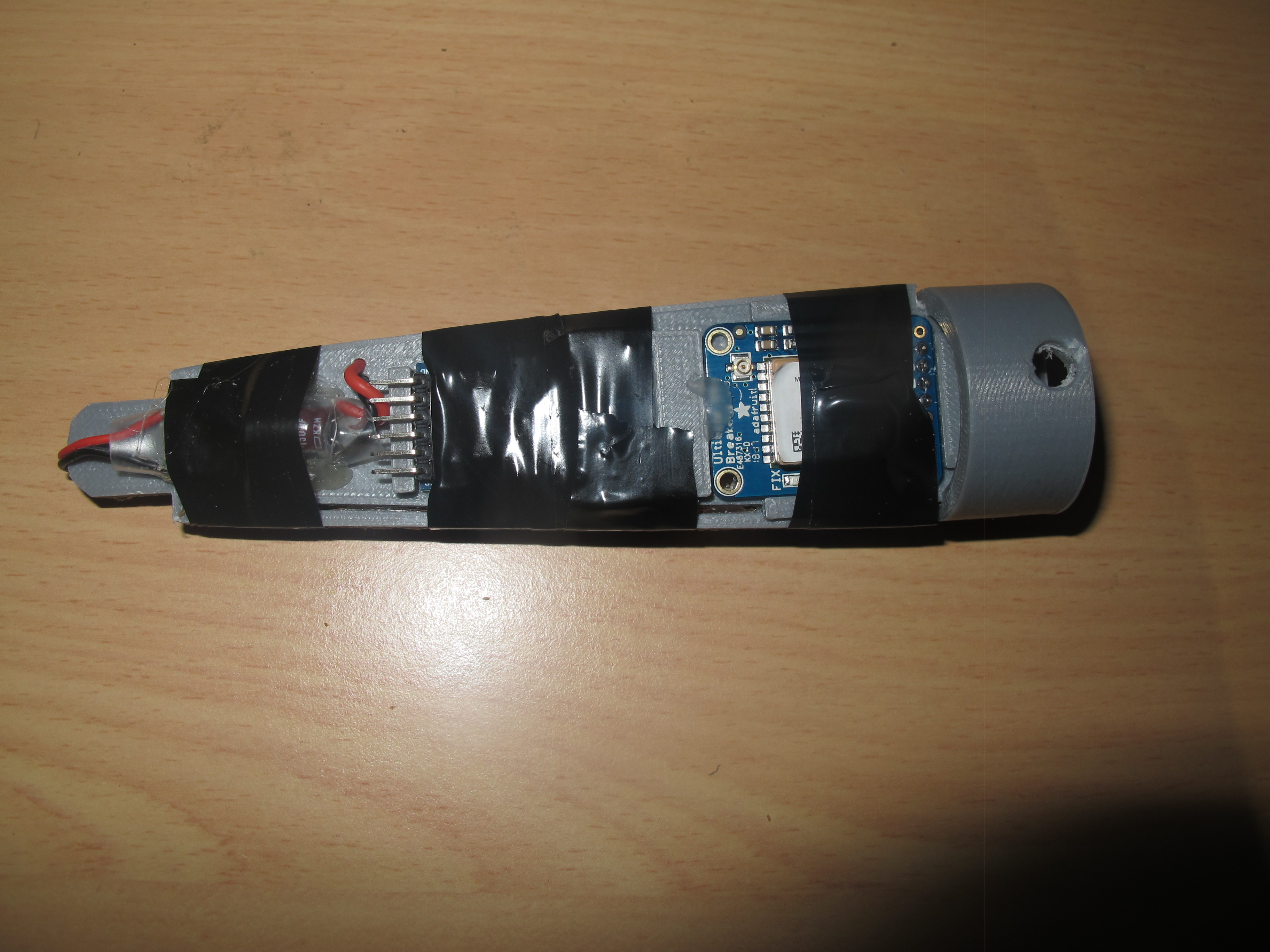
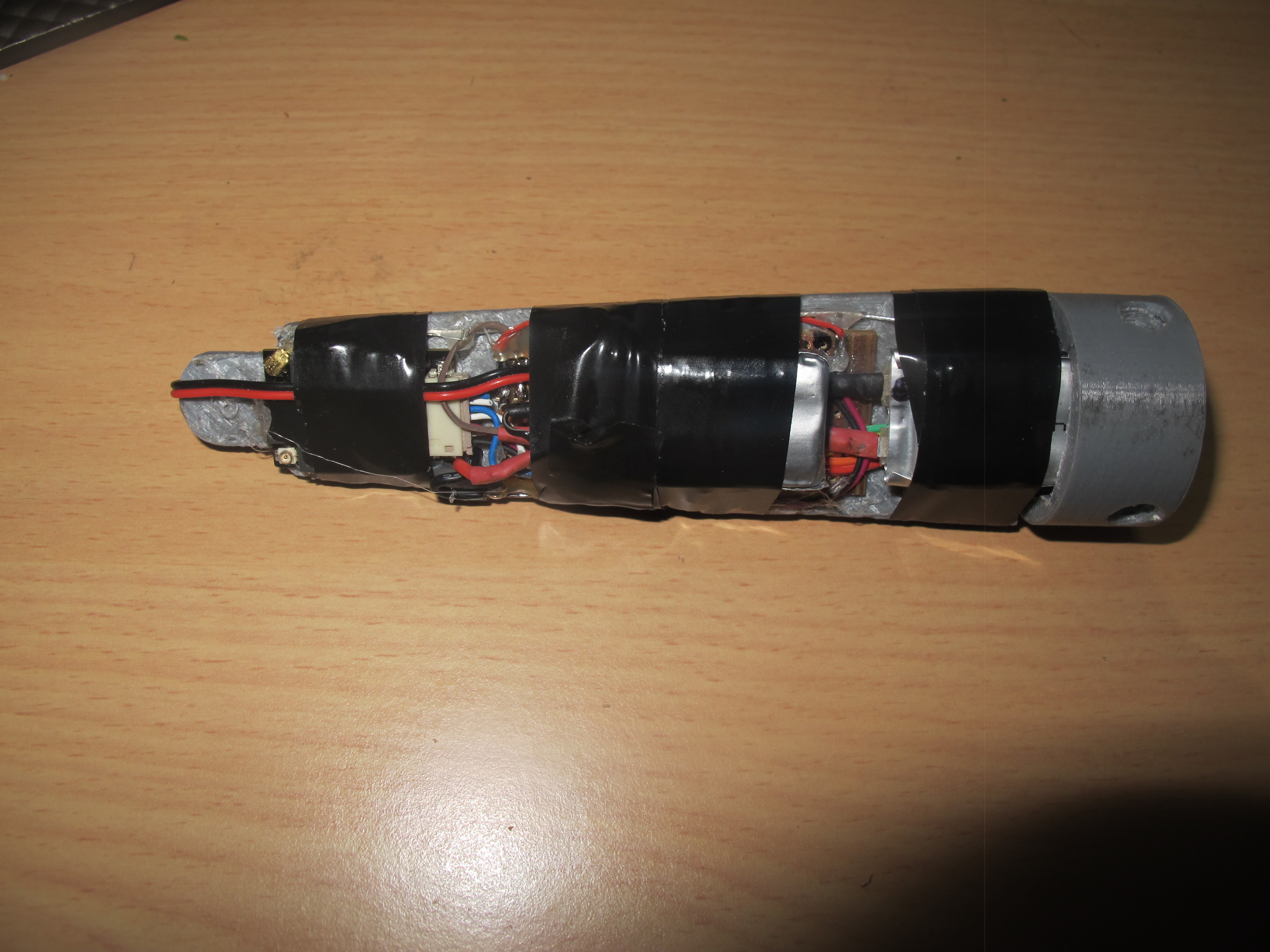
People at AusRocketry forum recommended some tape to ensure that the modem doesn’t rattle off. This sounds like a wise idea.
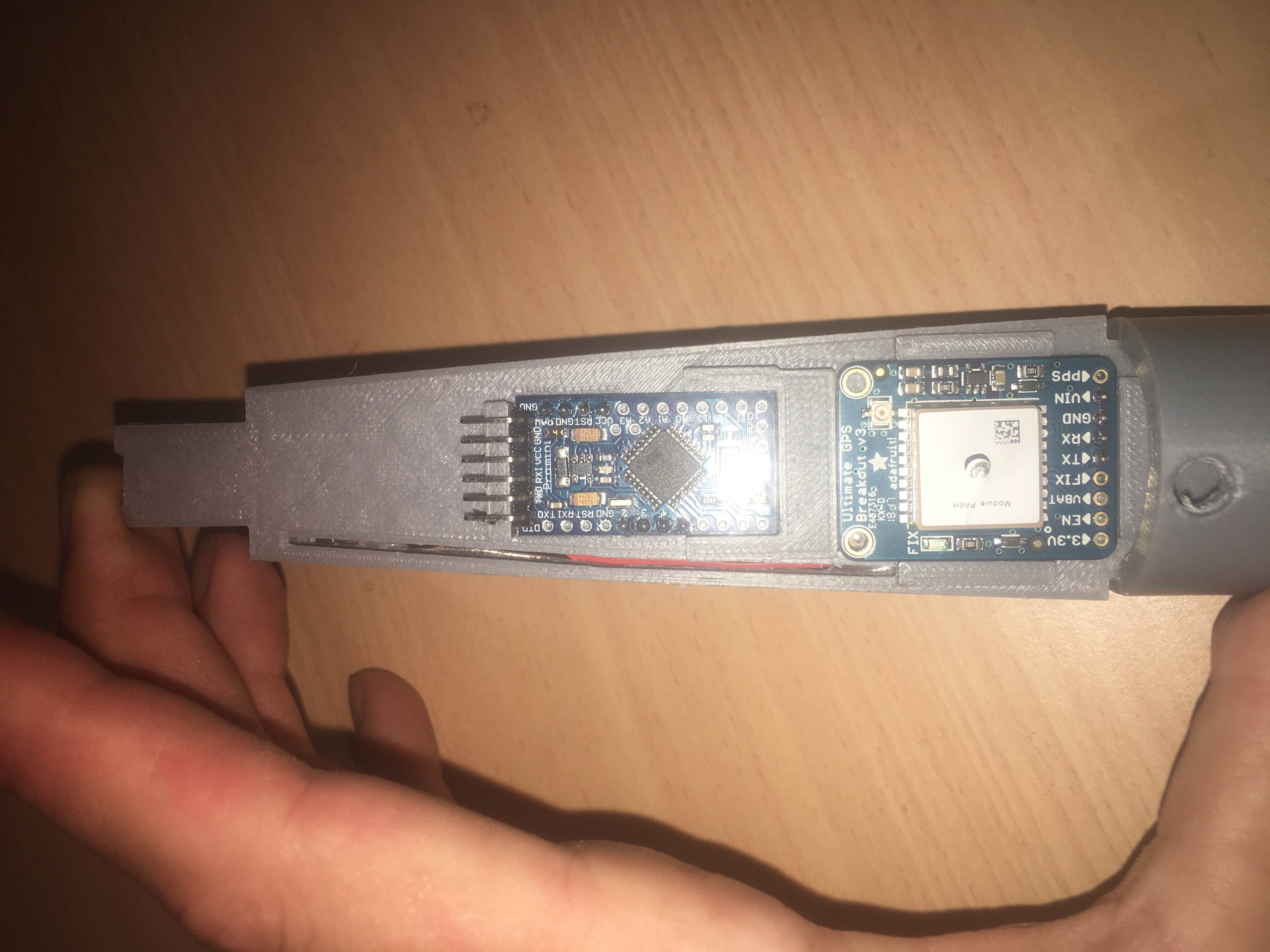
Break-out board side.Wiring side of Tracker Payload.
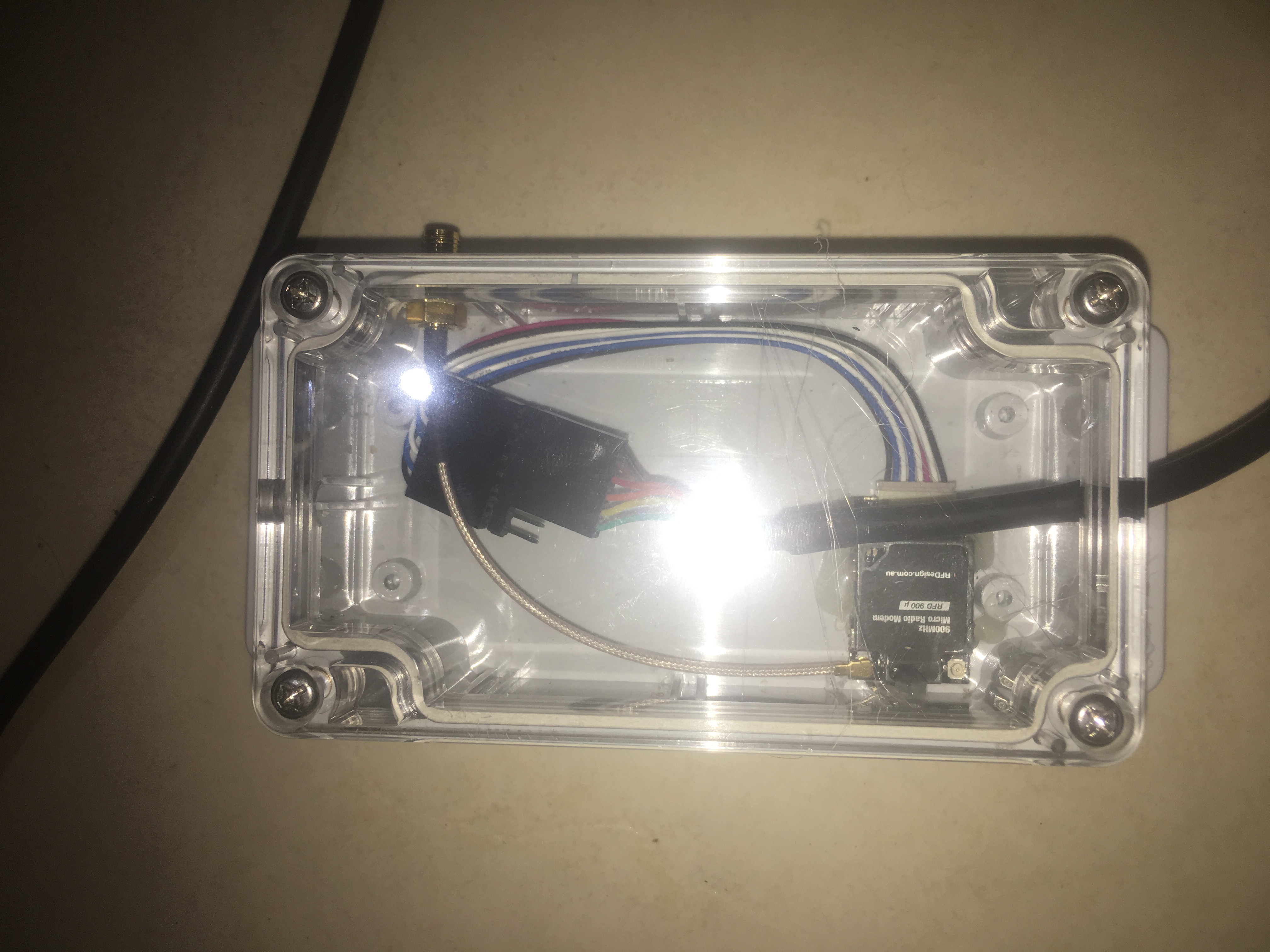
See the photo below showing the various parts of the tracker.
Various parts in the tracker.
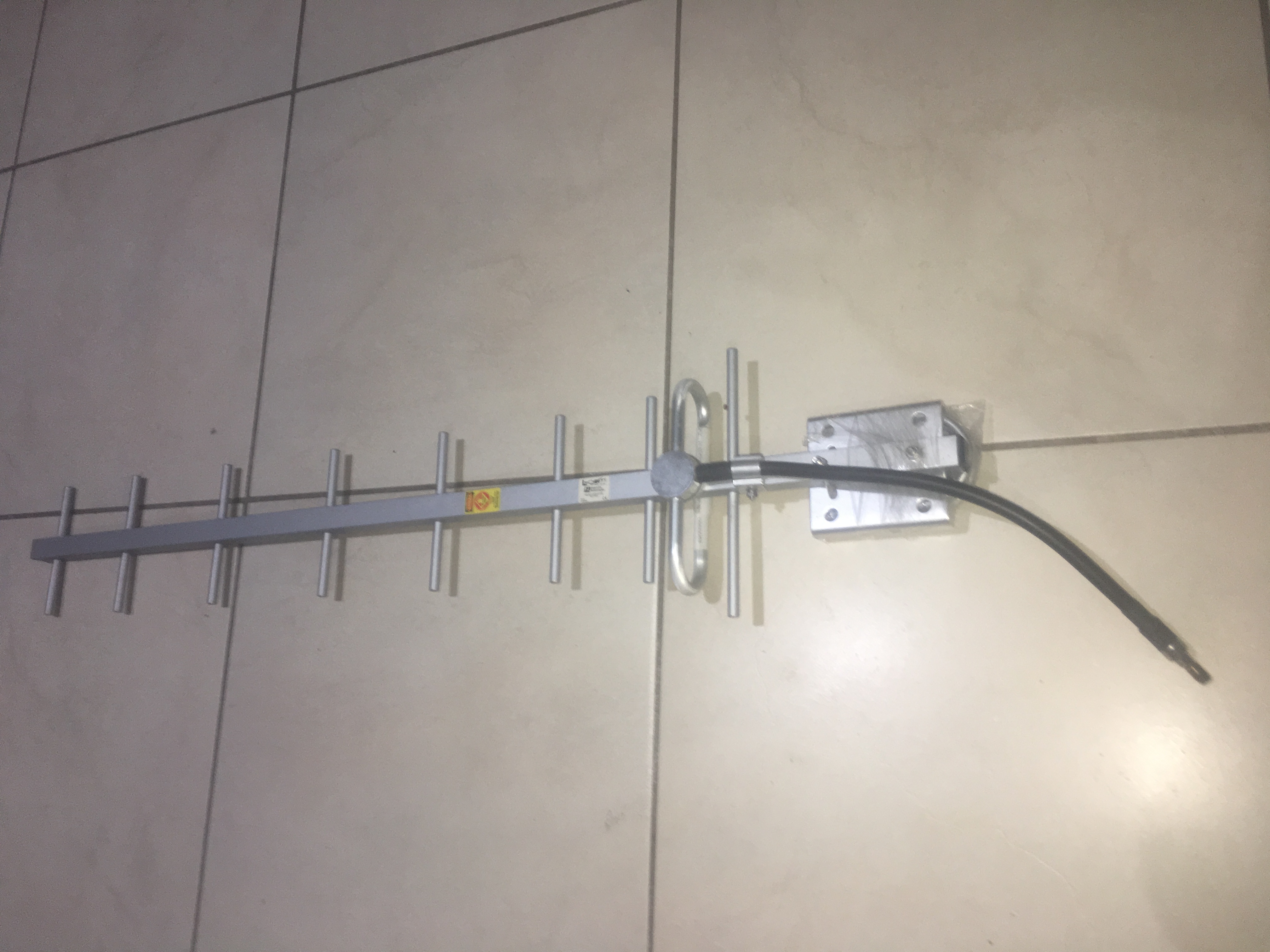
The Ground Station
Sole RFD900U modem unit for connection to computer.900MHz Yagi Antenna
Range Testing
I reduced the power on both modems from TxPower = 20 to TxPower = 5. Then I did some tests about 100metres away. I still got RSSI of about 120, which isn’t too bad, considering it is low power.
I estimate it should be able to do about 2km no problems with this configuration; with optimal environment i.e. LOS and plenty of clearance. Probably able to get a few more km in ideal circumstances.
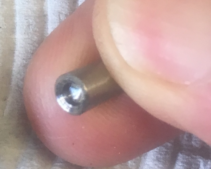
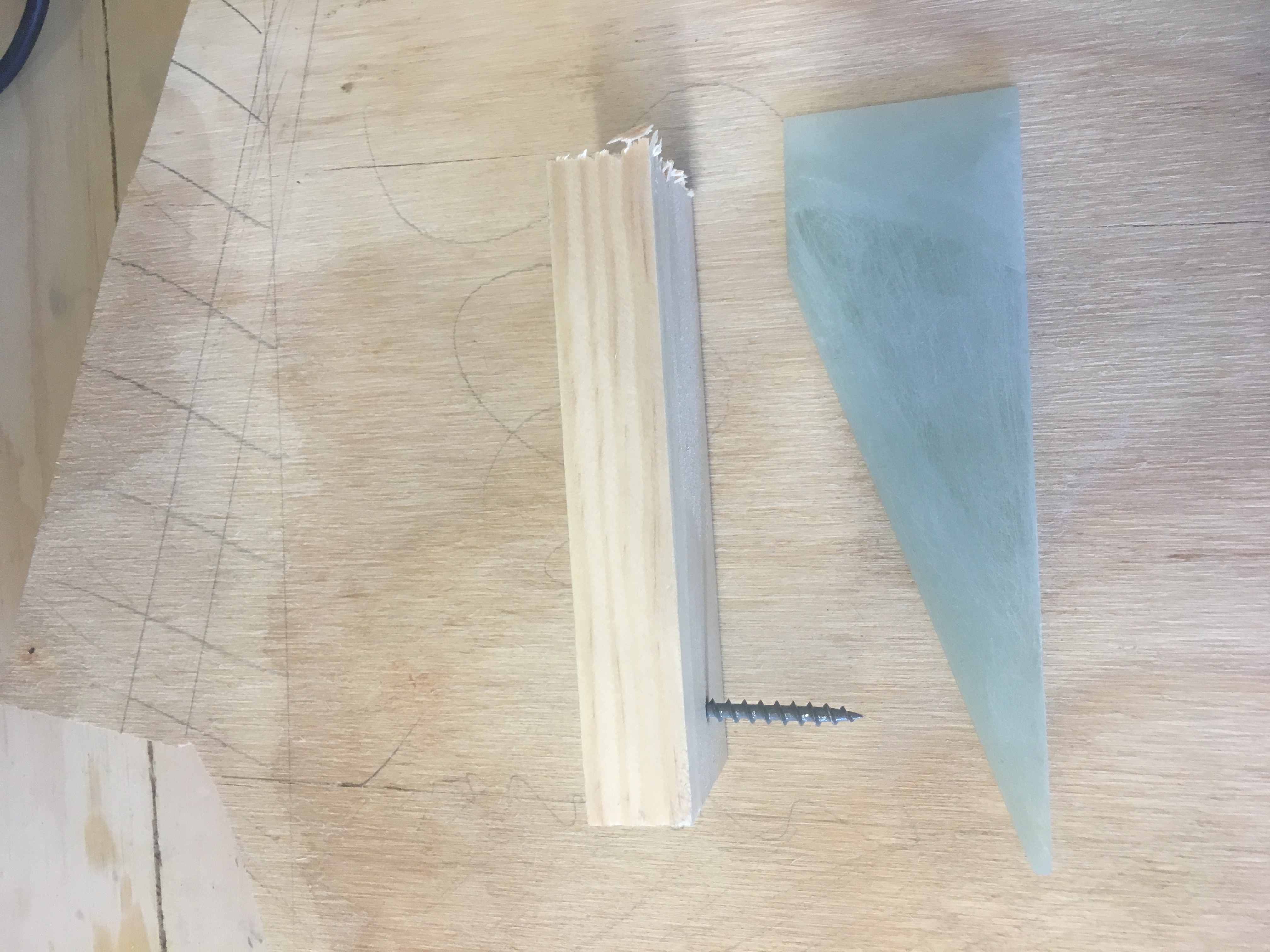
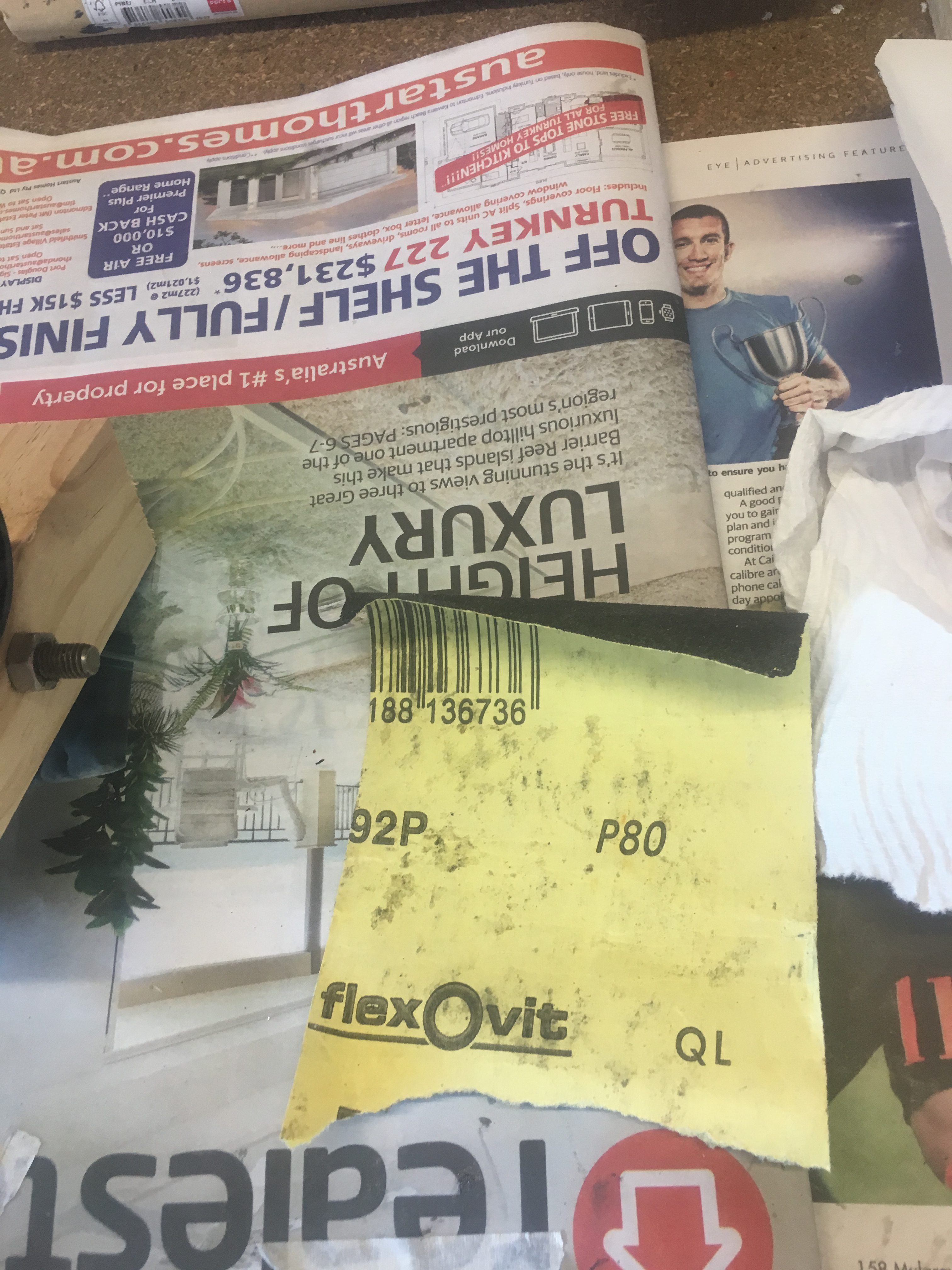
The Cable Cutter I purchased from Aerocon Systems has cambered edges as shown in photo below.
This should have a very sharp cutting edge…a concave hole.
According the supplier, this is normal of these cutters now and is on purpose because the Aluminum cartridge gets damaged from the sharp edge of the piston when too much Black Powder is inserted.
Creating a Cutting Edge
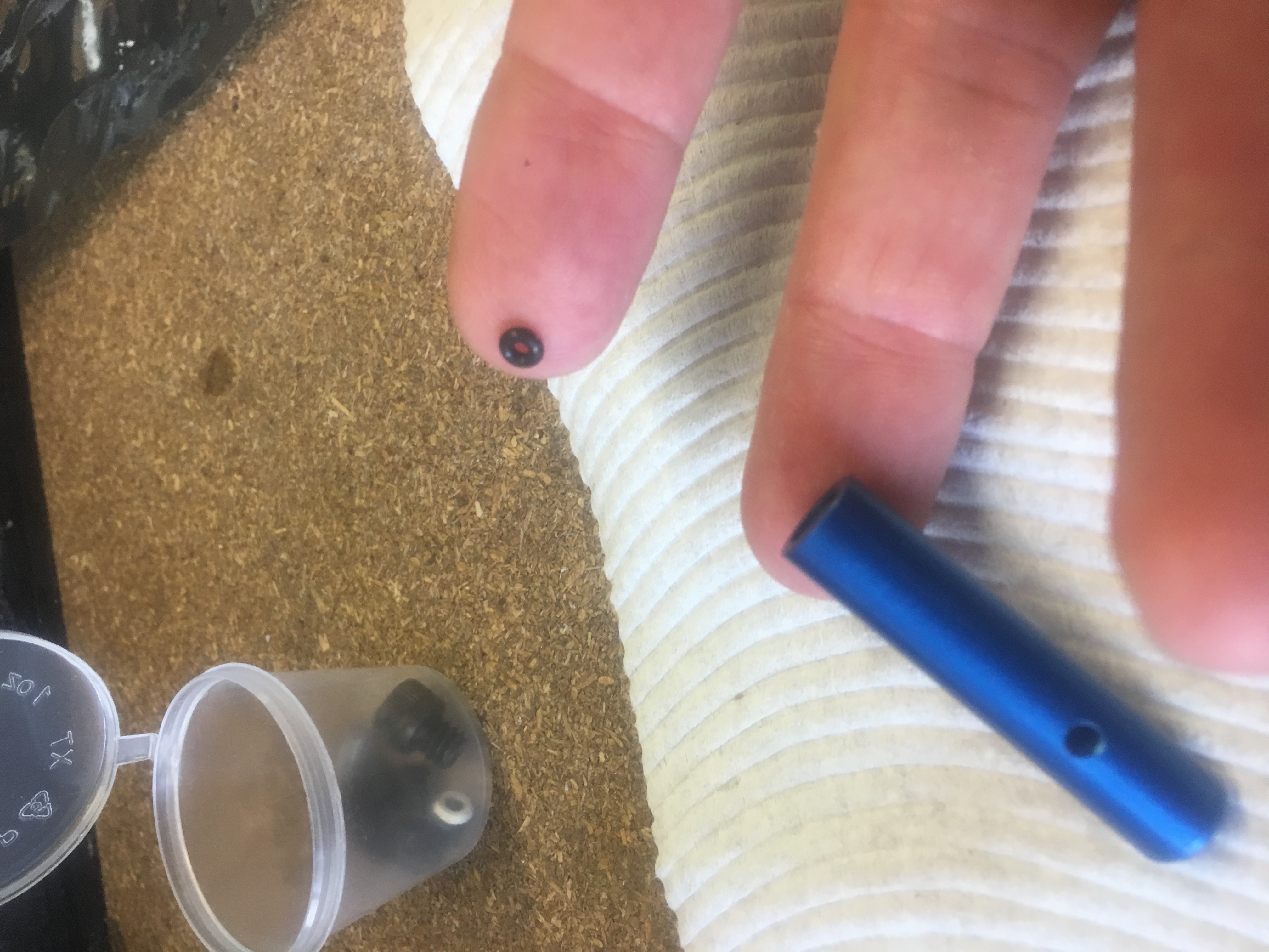
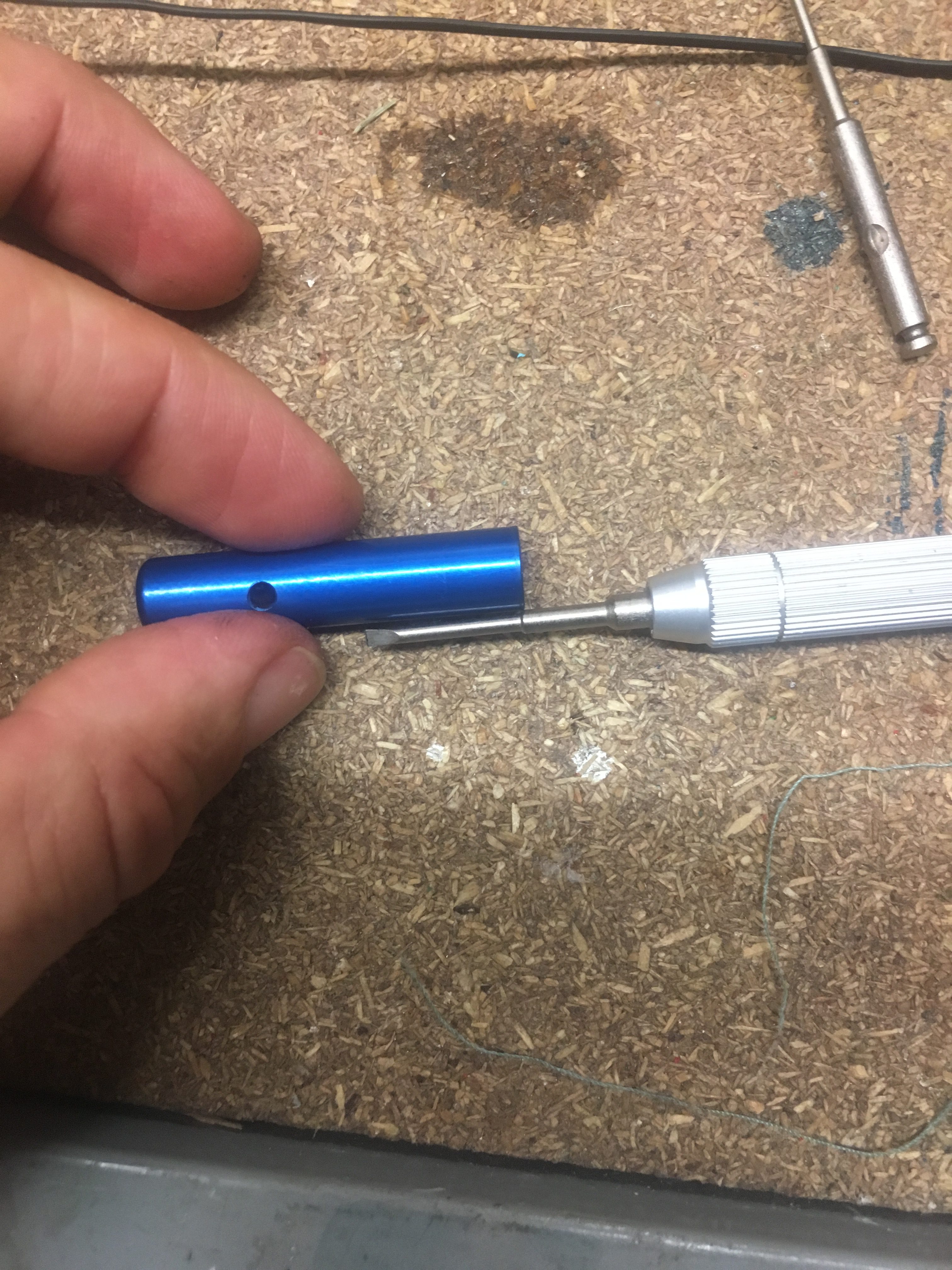
I decided that I would introduce some sharp edges because it just didn’t cut on my first test; and if it doesn’t cut the cable tie, it is of no use to me. So I drilled about 3mm into each end with a 2.5mm drill bit. Then I used a counter-sink bit to create a bit of a ‘crater’ with a sharp edge. See photo below.
3mm deep hole drilled with 2.5mm drill bit.
Precise steps were:-
I did this in the vice, very carefully using Aluminum brackets to not distort the steel piston. I marked the center point using pencil under magi light. Then I used punch to mark the center.
I went straight to the 2.5mm drill – special tip and used cutting fluid. It drilled just fine. Then after drilling to a depth ~3mm I used a countersink drill bit to go about 1mm in, to get a “cutting edge” just inside the main diameter.
Assembly
I assembled as follows:-
First goes the O-ring.
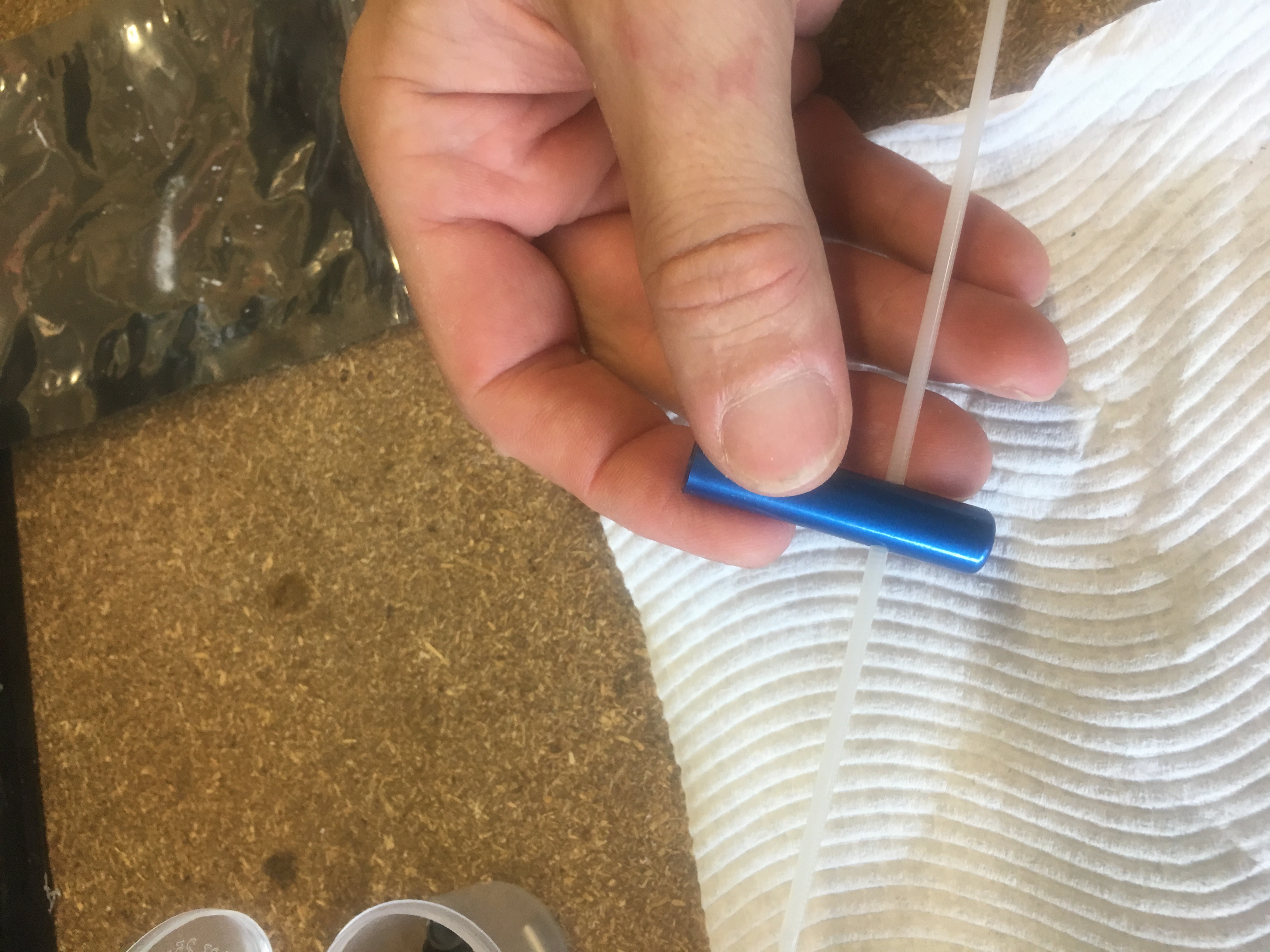
Threading the cable tie into the blue cylinder.Slotting in the Piston.
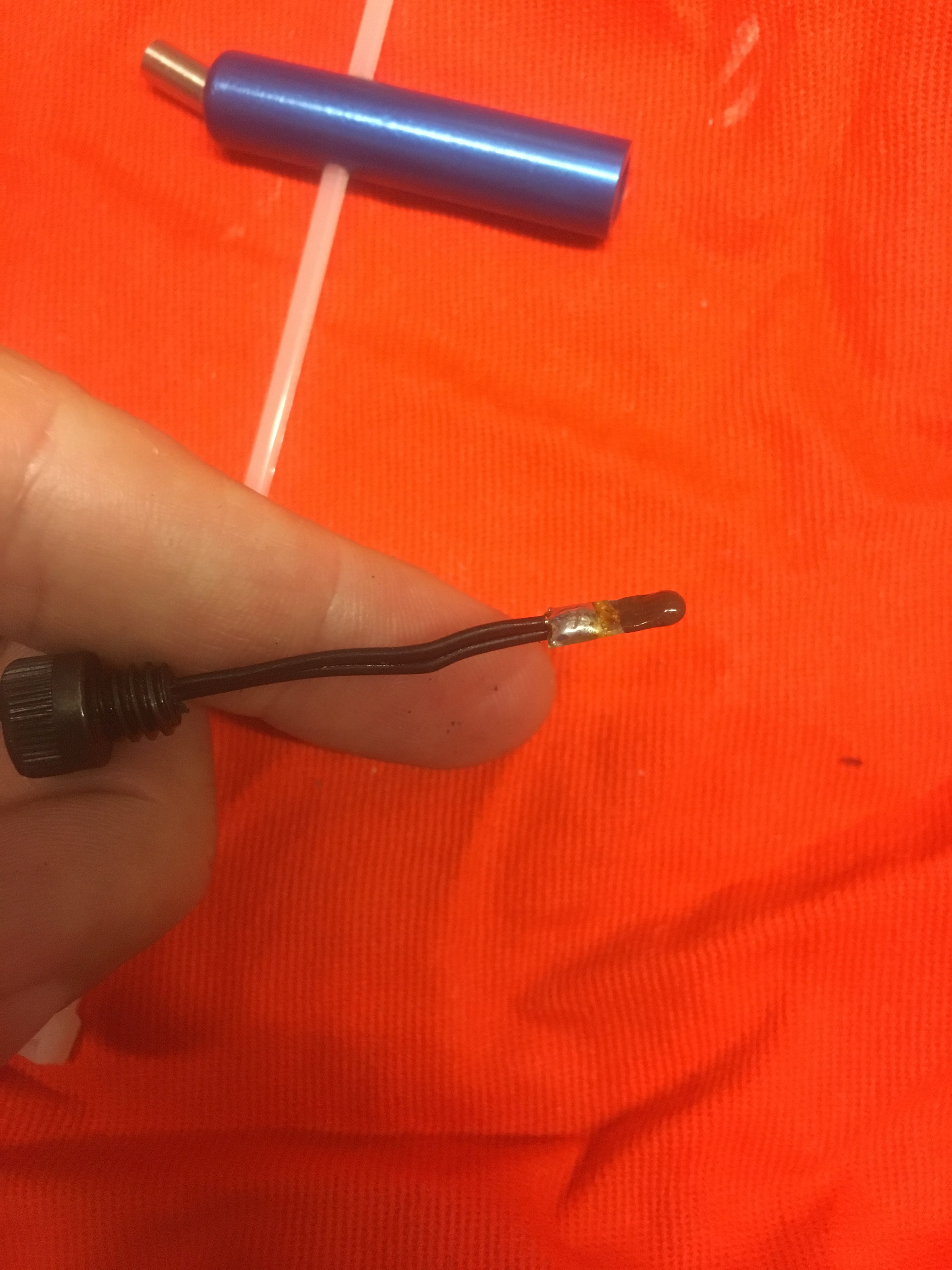
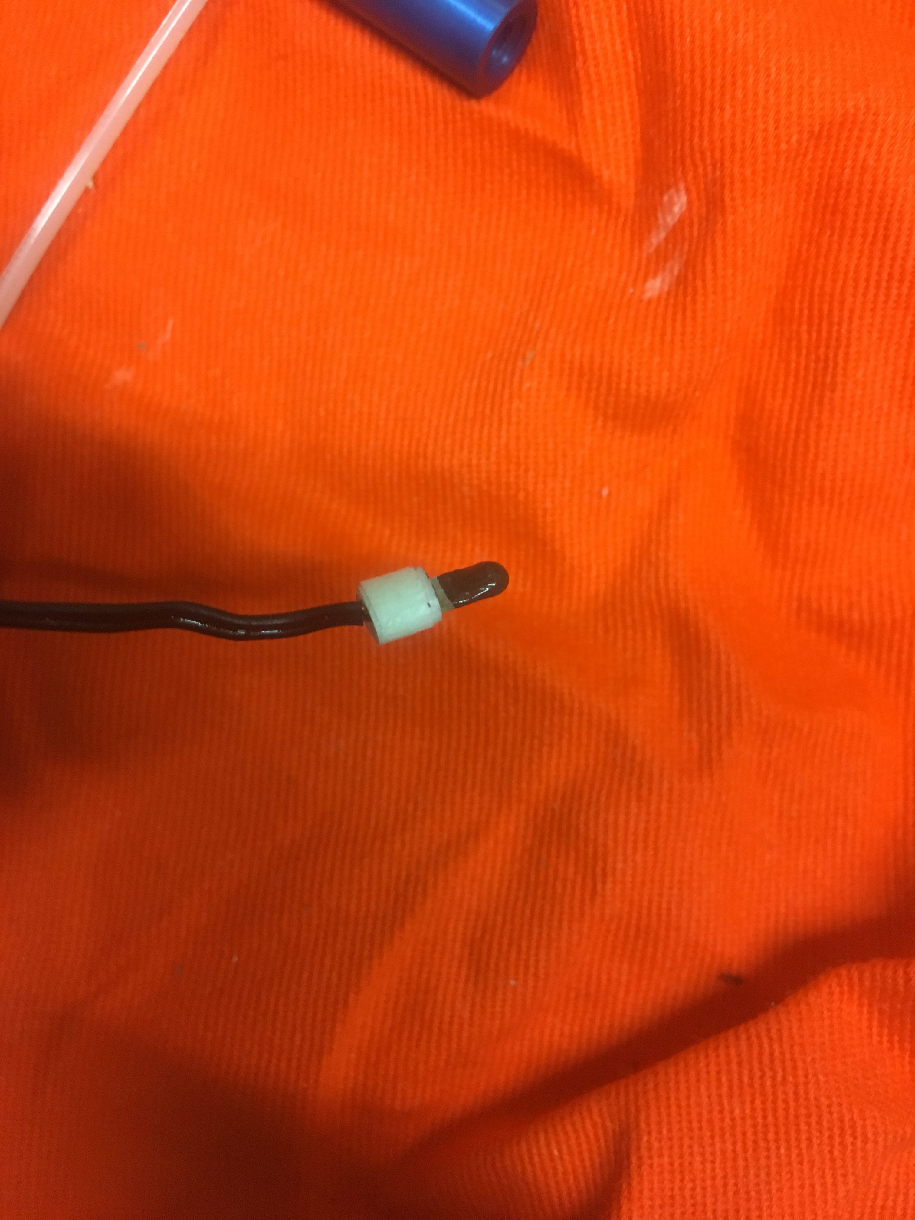
Next I straighted out the e-Match and took the red plastic protector off it. Then I rolled on a small O-ring. The O-ring has two functions:-
To help seal the cylinder, reduce amount of gas coming out
To stop shorting of the igniter contacts on the hex screw end bit.
Close up view showing the O-ring.Everything fitted and plenty of hot glue melted on to end to ensure no gas comes out the rear.
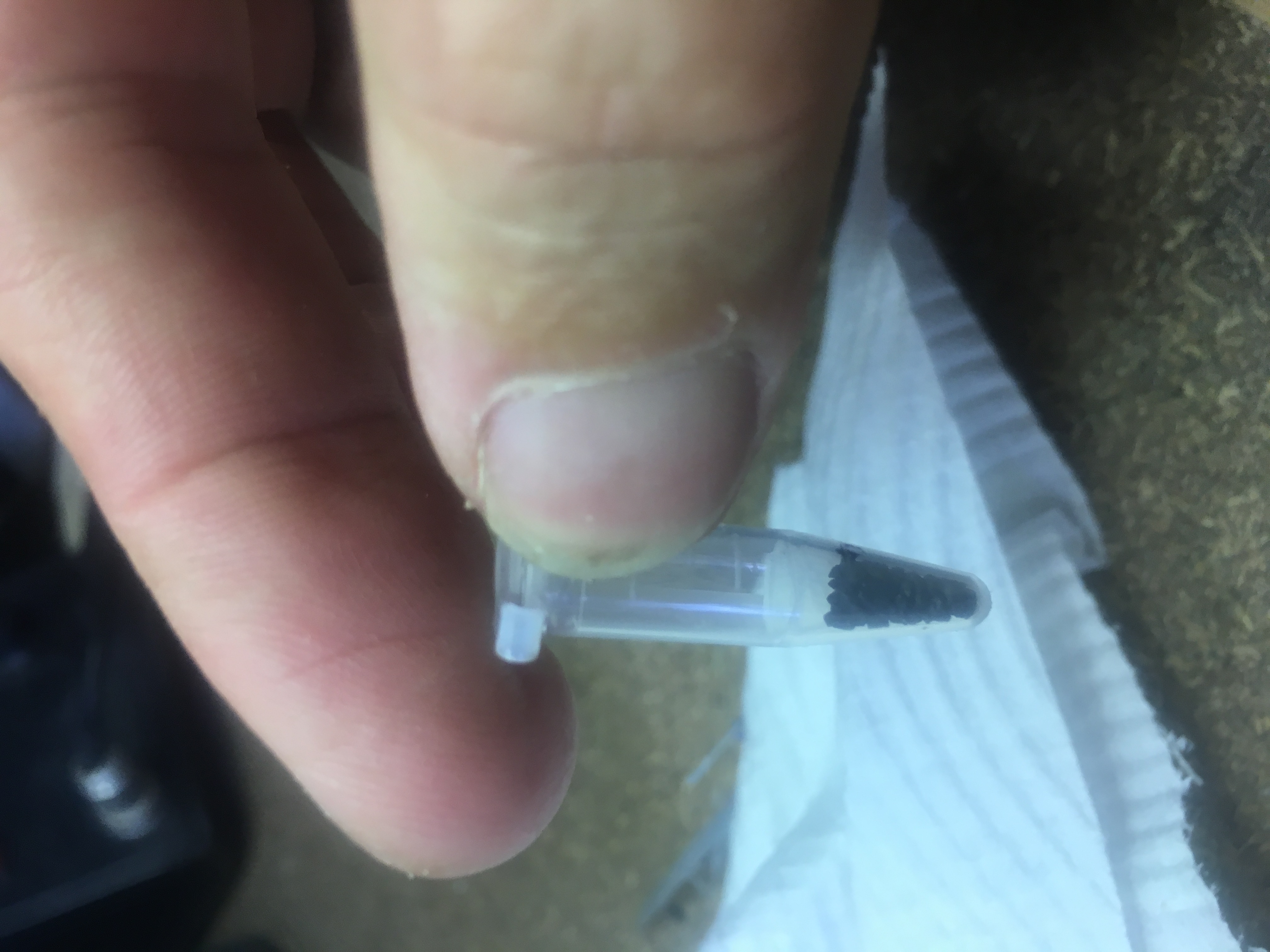
I then melted some hot glue on the end.
Then afterwards, I removed the screw bit…and put the measured 0.1 grams of black powder in.
I’ve progressively refined the design of an engine block. This is a device that sits inside the air-frame, about 1/2 way along the air-frame, either glued or screwed in. To it we have a hook for the shock cord and a the bottom we have a point to screw in the motor using Aeropack adapter.
Design 1
The initial design was using a 30mm Aluminum tube section with Aluminum ends and an eye bolt.
~30mm Aluminium Engine block
Design 2
This then morphed into a 40mm 3-d printed tube section with Aluminum ends with small shackles.
40mm 3-D Print version of engine block
Design 3
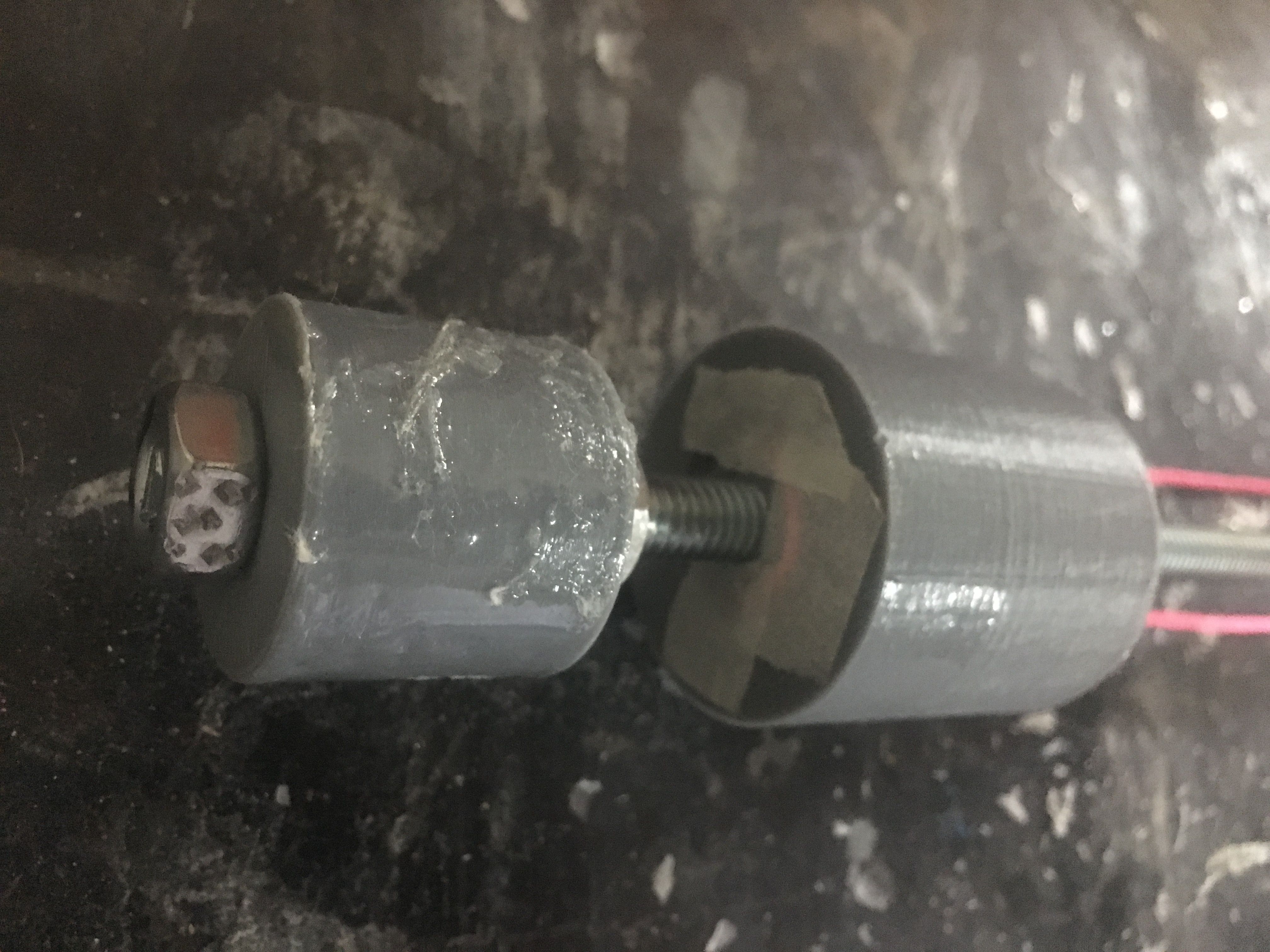
This then morphed into a 20mm 3-d printed tube with G-10 ends and a bolt with a welded nut.
Welded nut on bolt.
Design 4
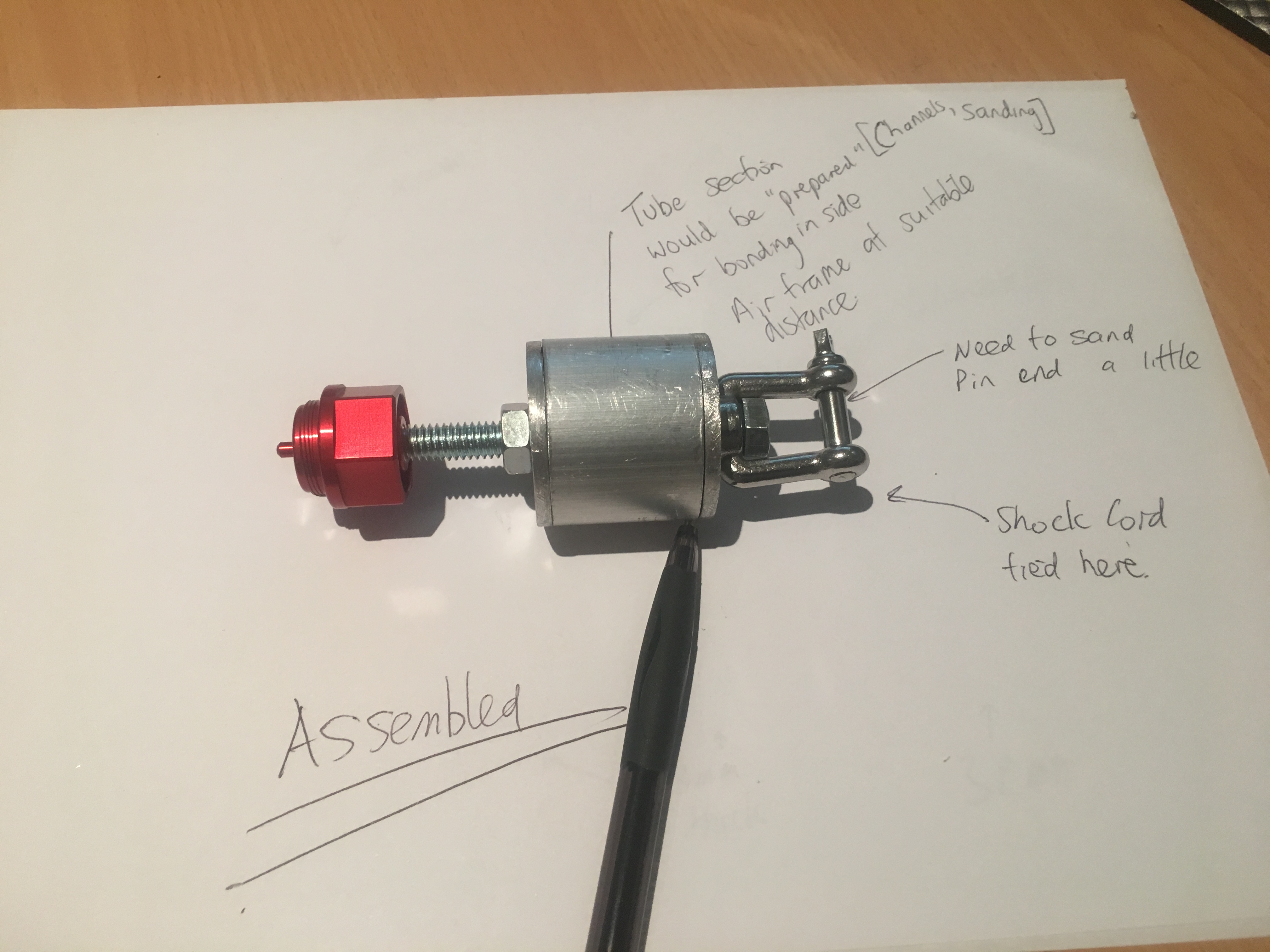
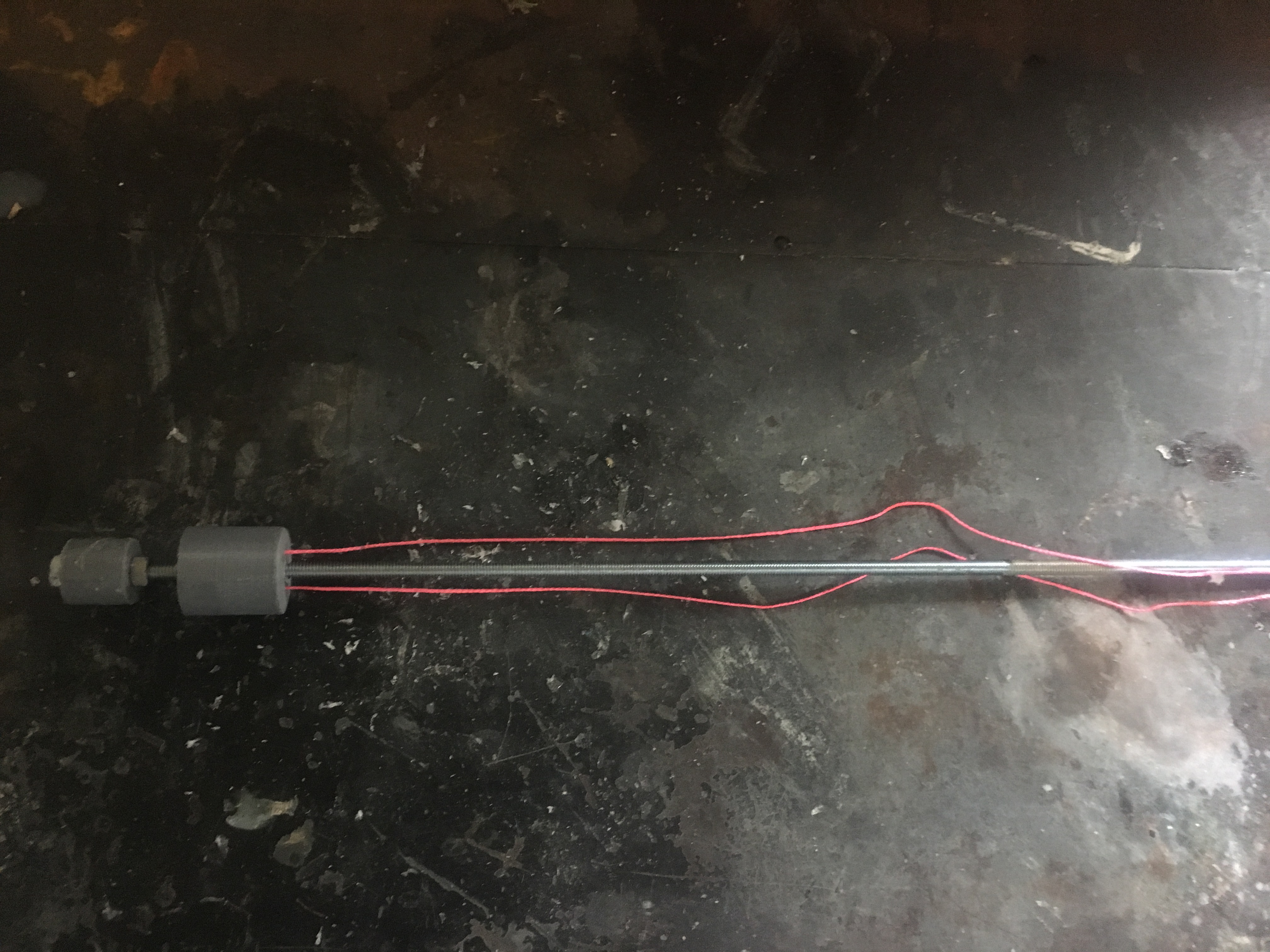
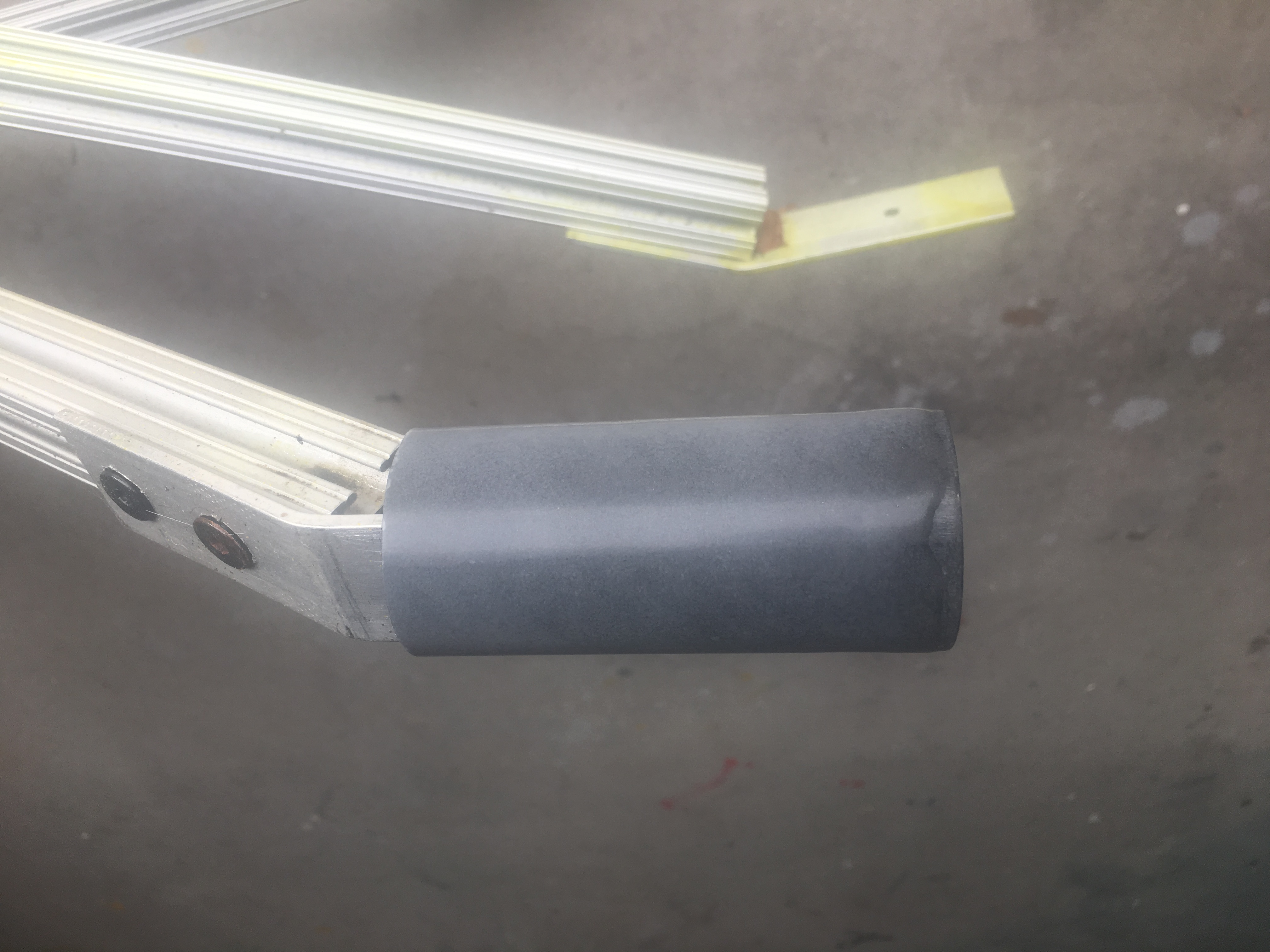
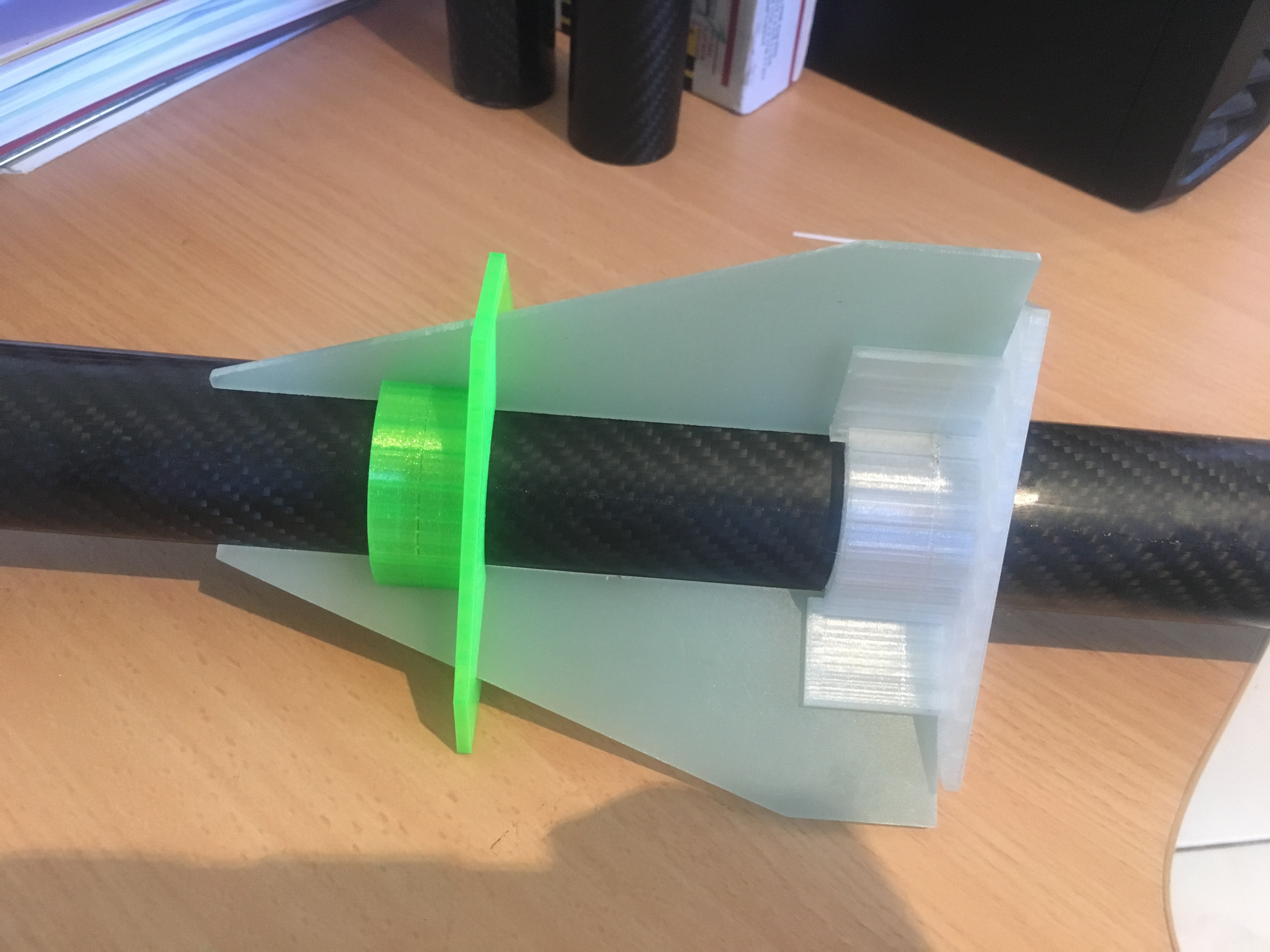
This then morphed into a 20mm 3-d printed tube with G10 material ends with much smaller bolt, with the one of the ends recessed 10mm from one end and a 3/16″ eye bolt screwed INTO the main bolt. Take note of the “channels” in the exterior of the block.
Latest version of Engine Block – Top view.Latest version of Engine Block – Bottom view.
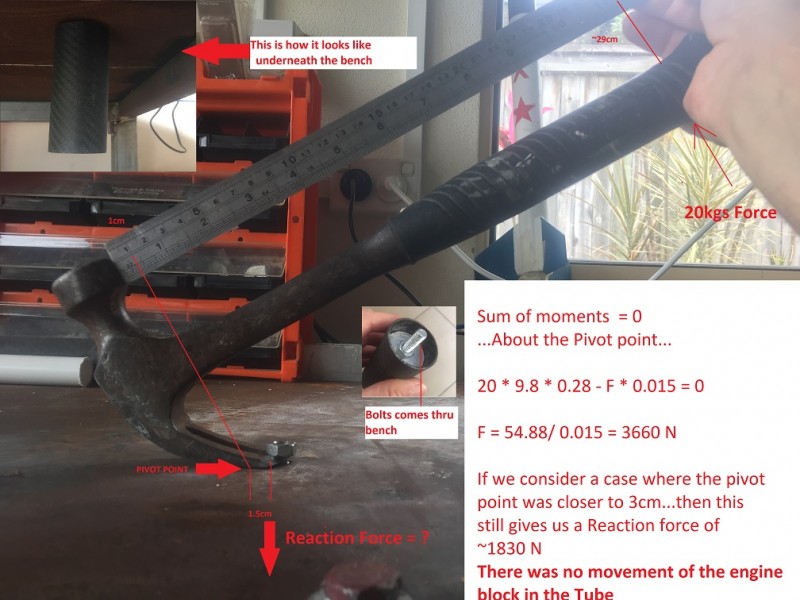
The last one can easily take 20kg load using the “hammer” test in BOTH directions.
Testing load on Engine Block
On the final version, I was able to exert 20kg loads in either direction without failure. Failure being movement of the Engine block. i.e. this design is adequate for the task.
Expected Loads
The thrust of the motor is expected to get up to ~800N in the UP direction. The force of the ejection gases is expected to be about 300N. i.e. considerably less. Remember, we are unlikely to use shear pins in the retention of the upper segment of the air-frame. Instead, we will use strategically placed tape to provide interference fit that requires certain level of force to overcome.
How it was glued in
I marked distance down the air-frame where I would glue the Engine block. This was to be sufficiently far in so I could install a 6GXL motor case in the future, if I desired.
Next I sanded the internal surface with GRIT-60 sand paper on a stick and then I cleaned it with a damp rag.
Gluing it in was not a simple task. I had to apply glue to:-
The block itself, in the external channels using a blade to ensure there was minimal excess
The inside of the airframe.
I wanted so smear enough epoxy in the RIGHT place in the air-frame. I created a contraption that I would guide along a 5/16″ rod to the correct distance along the air-frame and then I would let it touch the inside of the air-frame as I rotated the air-frame.
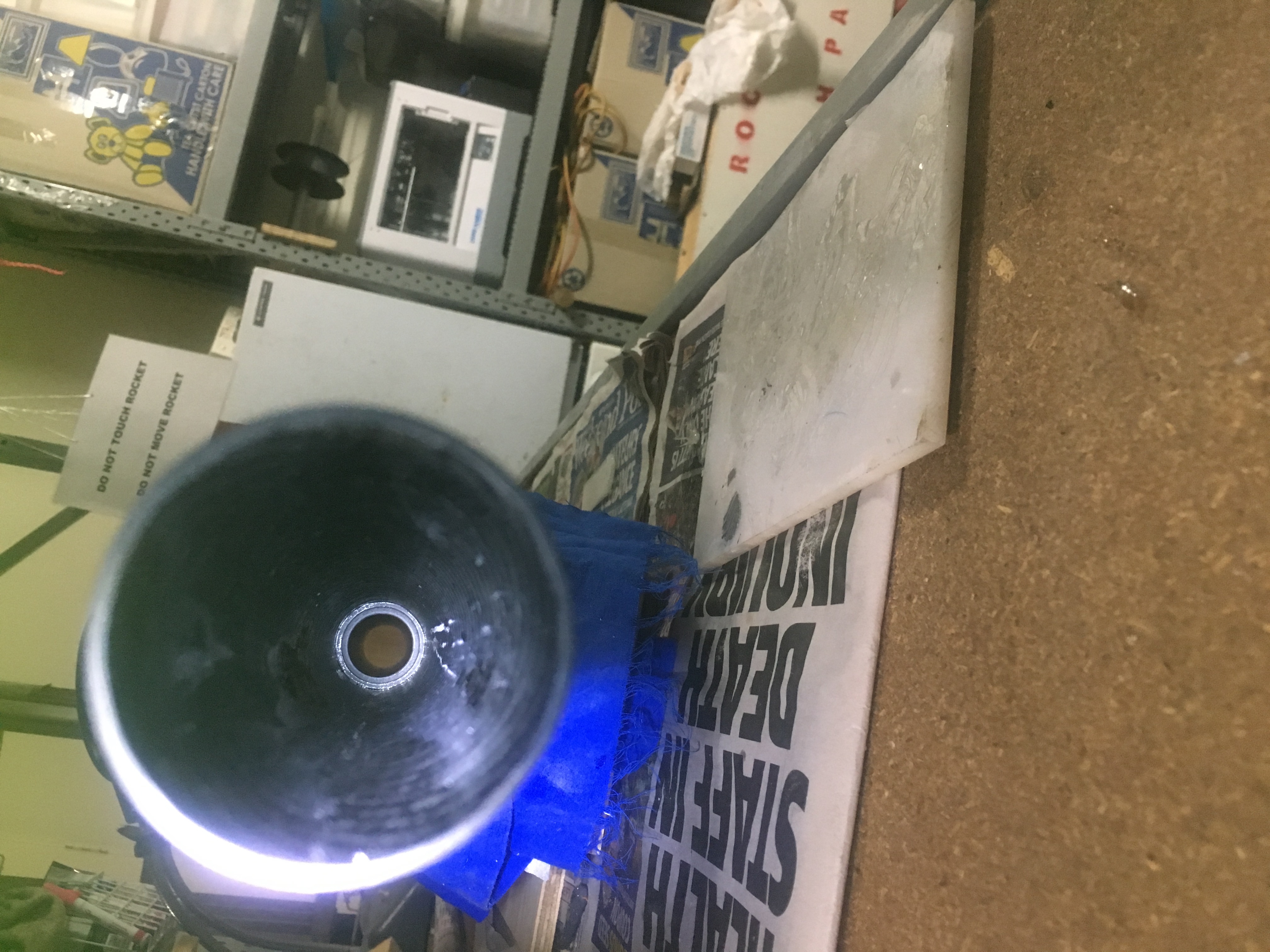
Contraption to apply glue to specific area inside air-frame.Close up of contraptionInside the air-frame after putting engine block in.Inside the air-frame after putting engine block in.
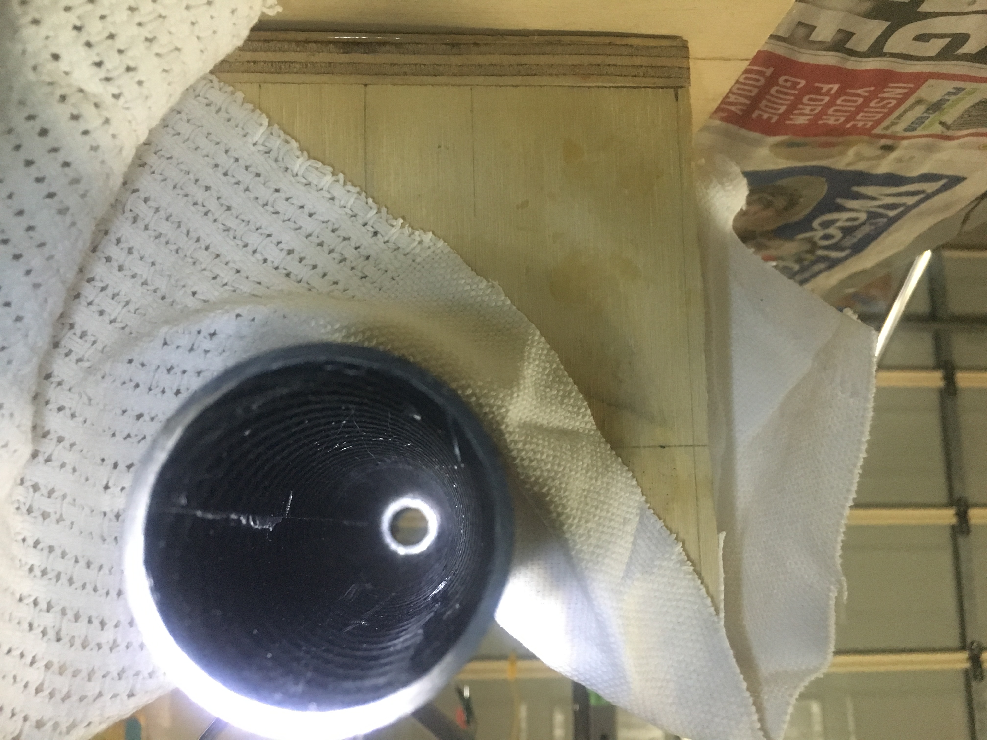
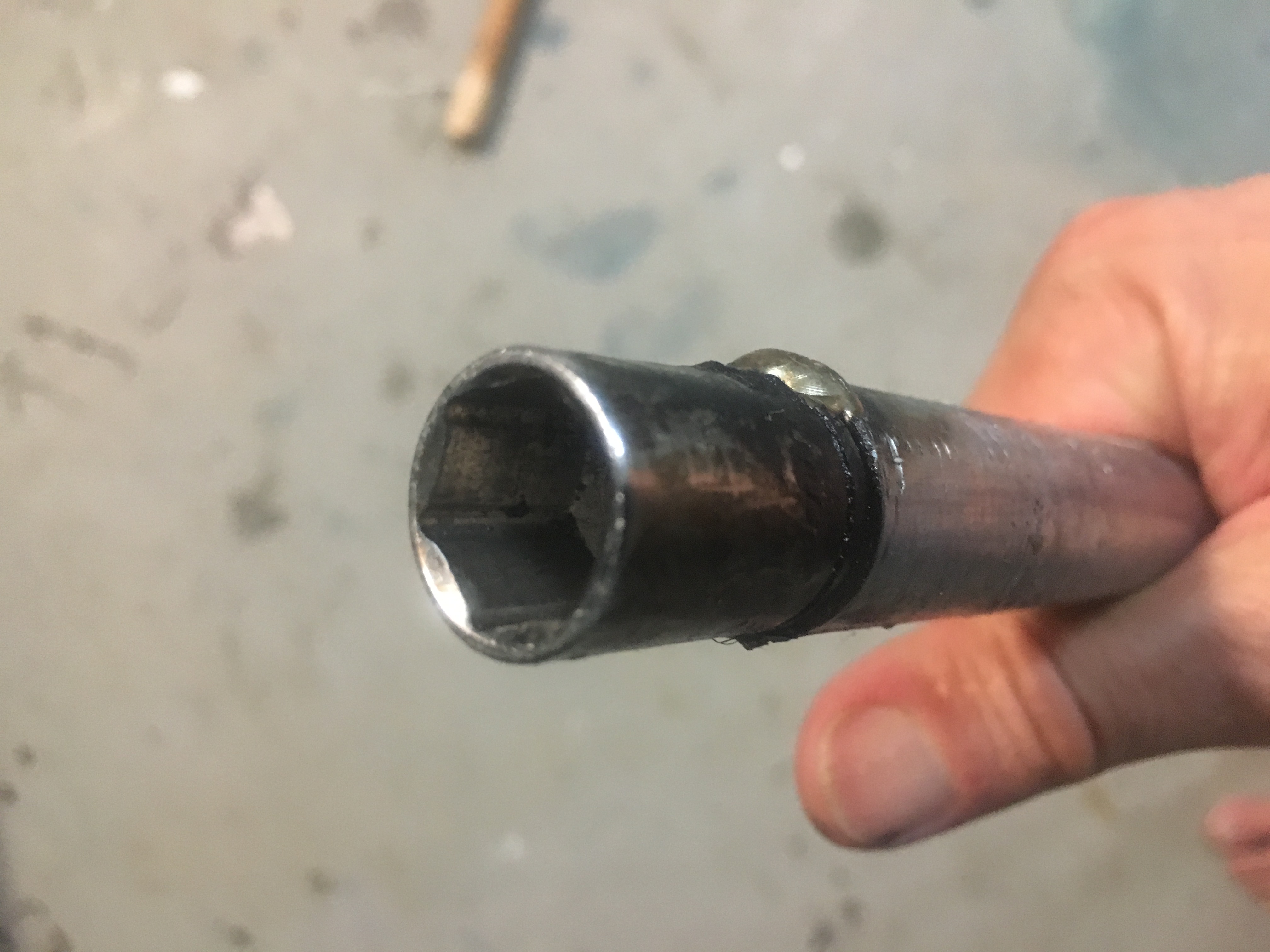
How to assemble it
It is difficult to assemble without some special tools. Below are some photos of some tools I created to get access to the parts.
Close up view of socketHollow steel rod with socket welded.
I had to weld a socket onto the end of a large steel tube. The tube was sufficiently large so that the bolt could easily go into the pipe, so I could be sure to completely tighten the nut onto the bolt.
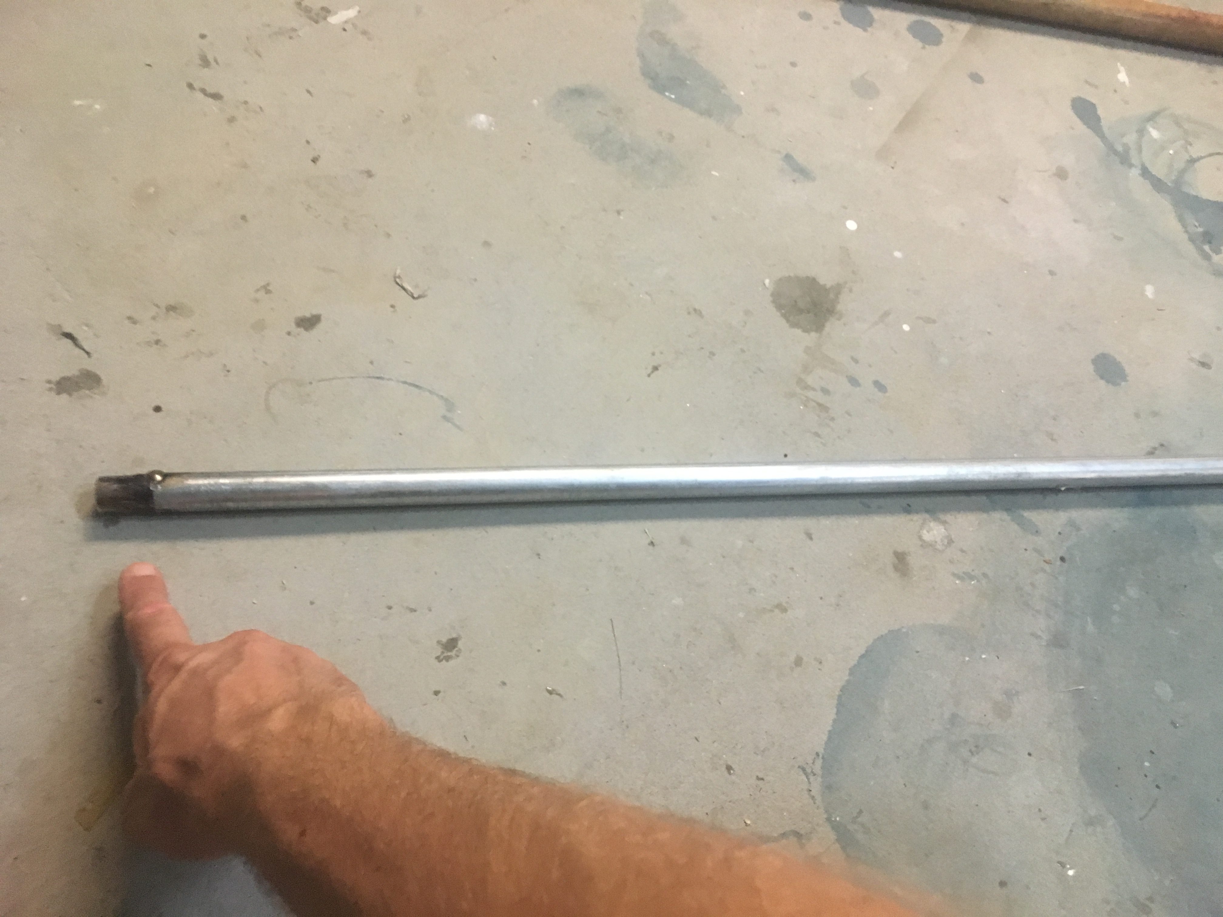
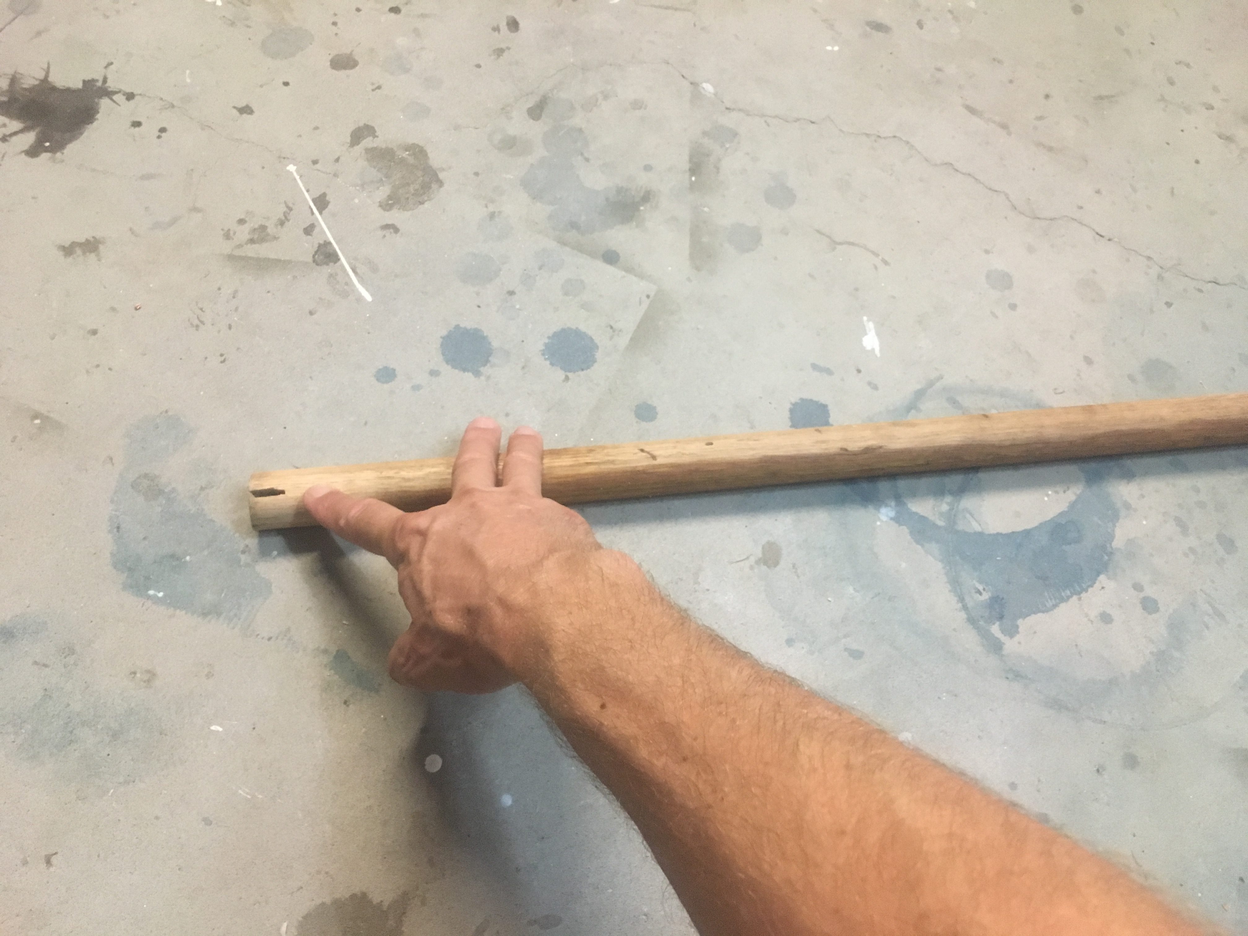
Wood tool with slit to hold the eyelet bolt.
The other device was a solid piece of dowel in which I cut a slice into it, so I could friction-fit the it over the eye-let bolt.
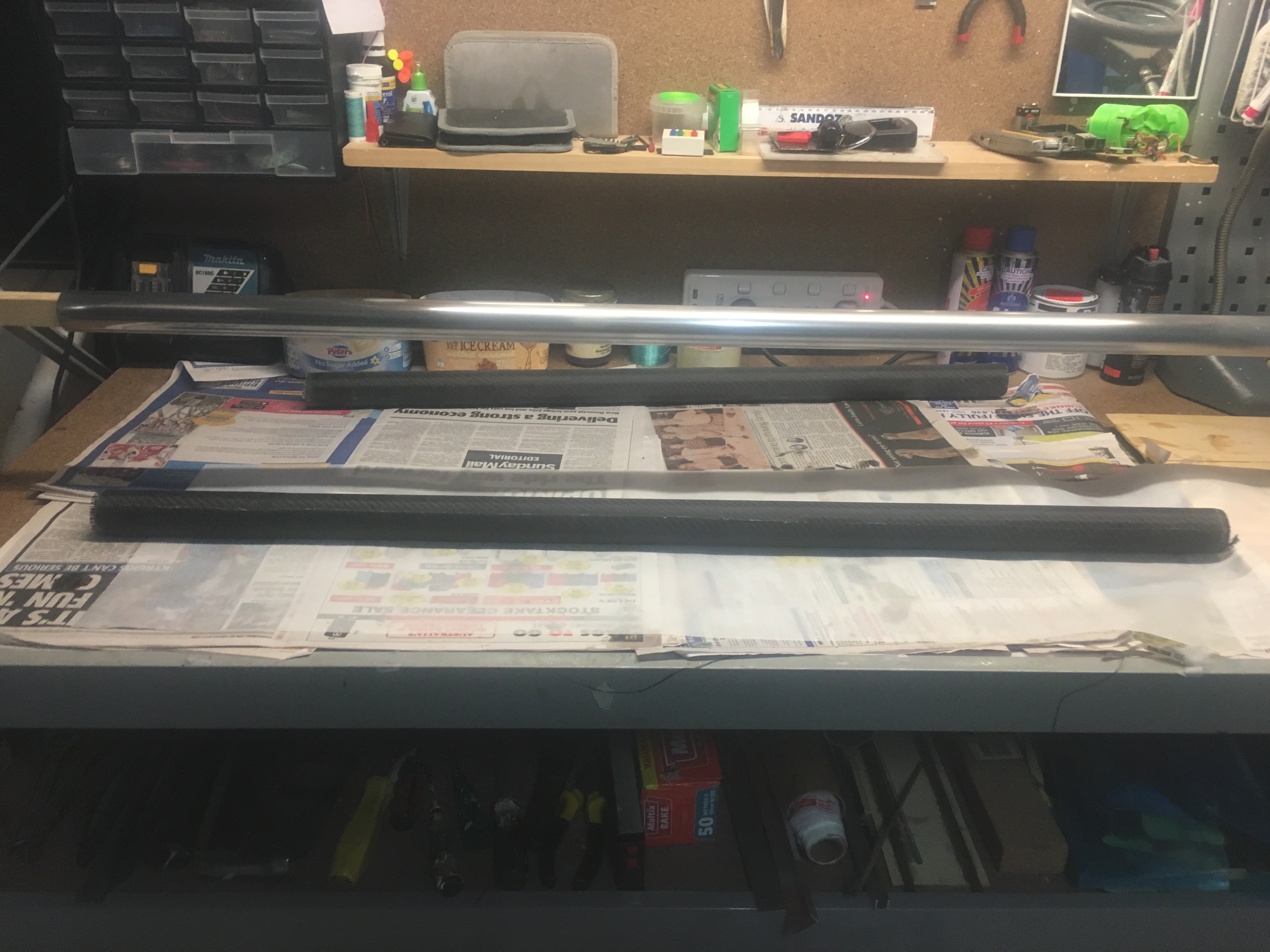
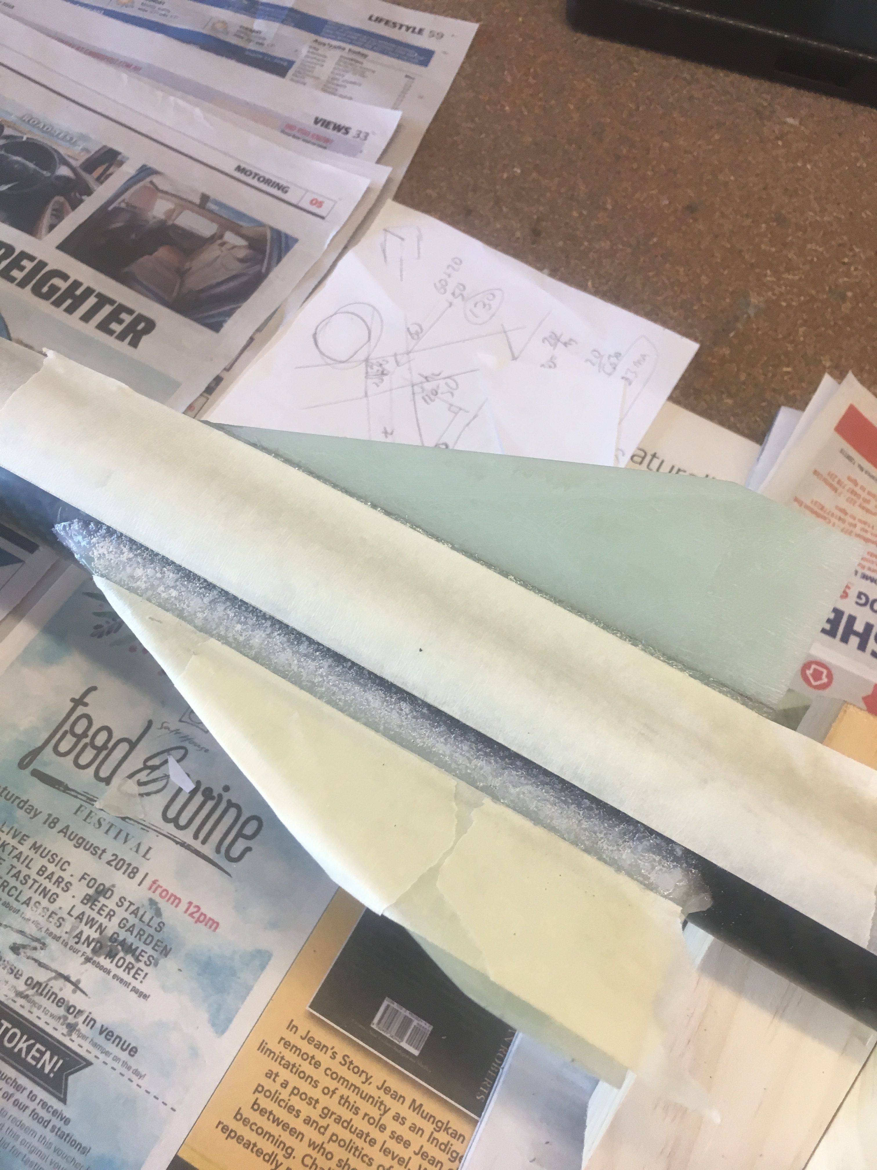
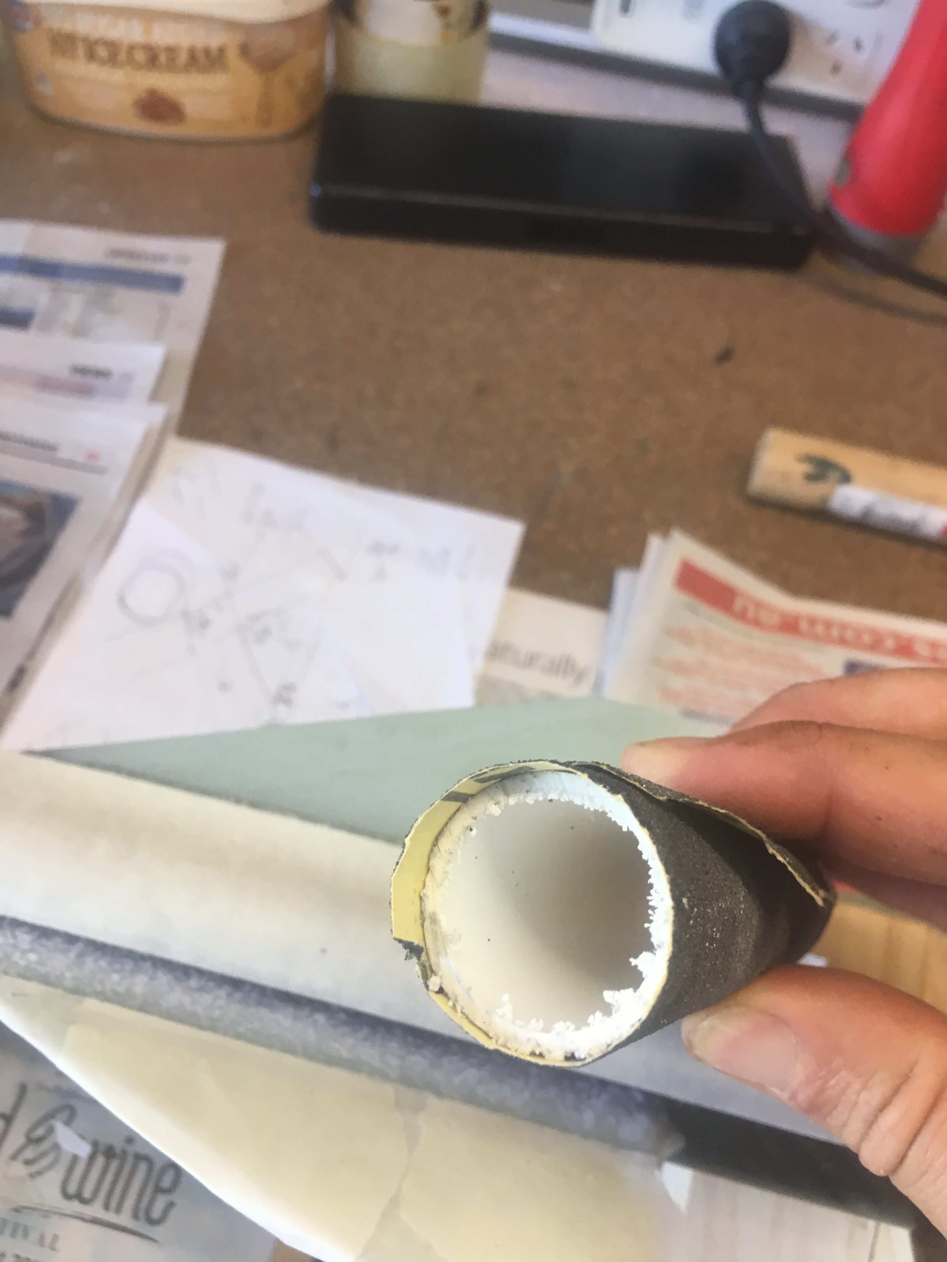
I have on my work-bench two posts at either end held in place using G-clamps. Then I have a sanded down length of wood with a Aluminium Mandrel that slides over this wood. The Mandrel is 38.10 mm in diameter and is 3 mm thick.
Mandrel preparation
The Mandrel was sanded using 120 right down to 1500 wet sanded. I then cleaned it with Methylated spirits and then I used Brasso to bring up a really nice shine. Then I cleaned it again with Methlyated spirits and paper towels. I did many goes over this to ensure there was absolutely no grime at all. On the left hand side of the Mandrel I beveled the edge to ensure there was nothing sticking out that might stop me sliding off the air-frame.
The Aluminum Mandrel – Made very shiny using Brasso.
NOTE: Brasso is a Coles product in Australia. It is supposed to be for Brass, Steel, etc, but Not Aluminium. It’s sister product Silvo is meant to be for Aluminium, but I found Brasso did a much better job.
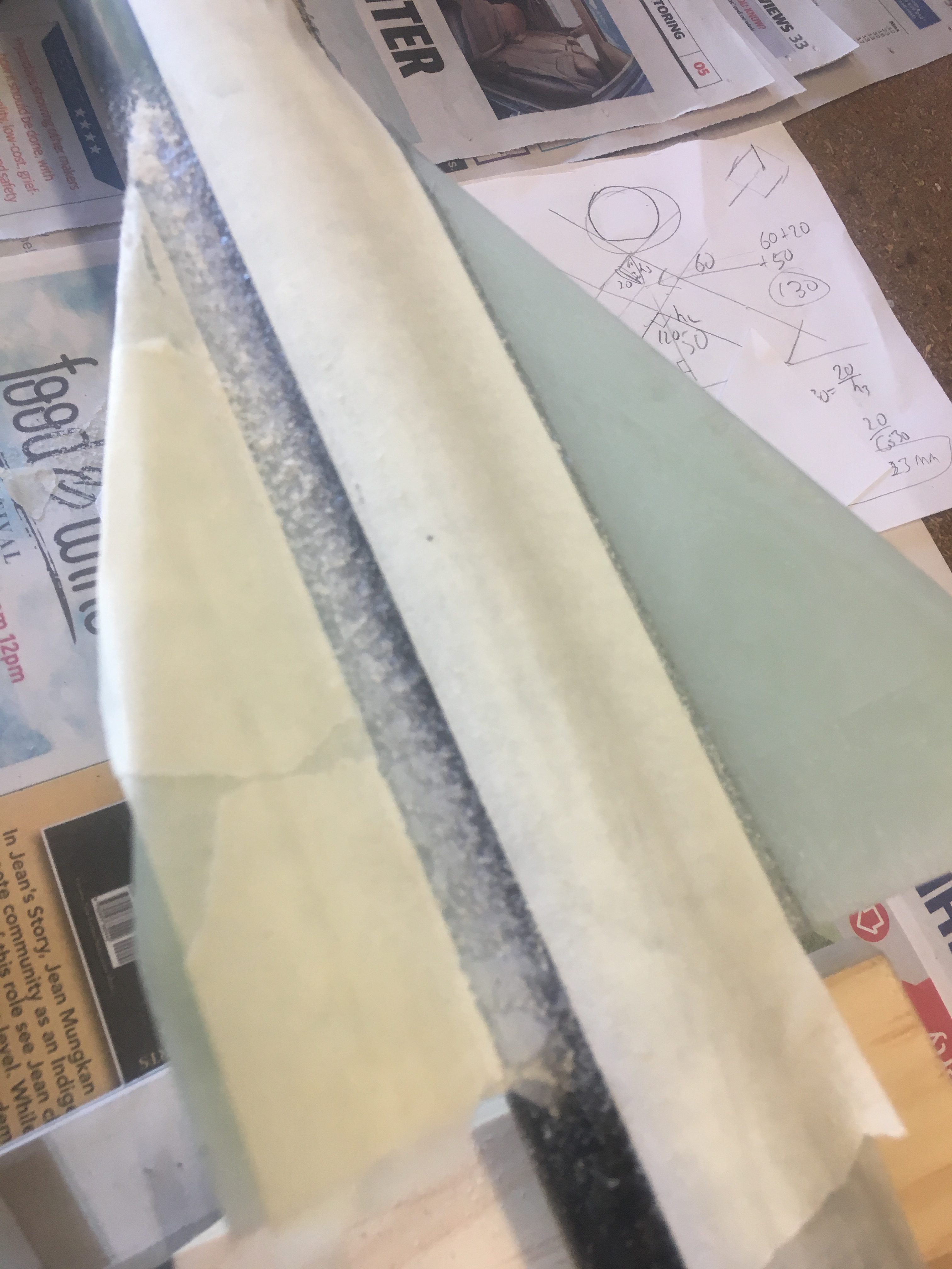
After the mandrel was cleaned up, I got some Glad Bake grease proof paper and cut to the following dimensions:-
1300mm x 280mm
This was wrapped around the Mandrel length-wise so that it went around twice + ~10mm. It was then glued to itself using a GlueStick. I confirmed that it was reasonably tight and could slide. The left hand side is the end I get the Air-frame off.
The Peel Ply
I use Nylon Peel Ply.
It has a red-trace about every 50mm through it. I cut approximately 300mm of it off the 1270mm reel of material. I then used my USB heat gun device (that came with the 3-D printer) to cut off the 20mm off one of the long edges to give us a straight edge with no loose threads. I then did the same with the other long side so that I had the Peel Ply with dimensions 1270mm x 265mm – with no loose threads.
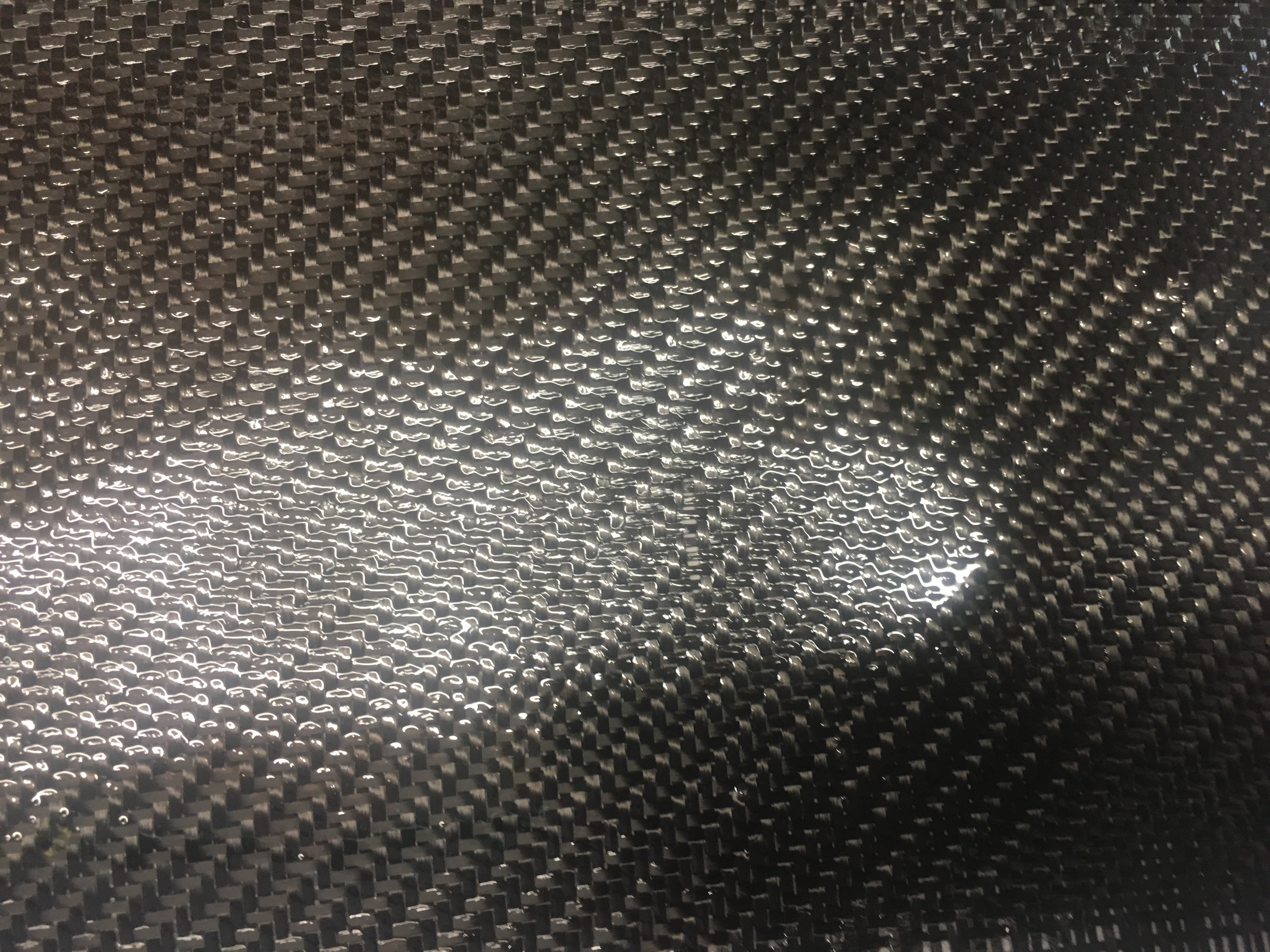
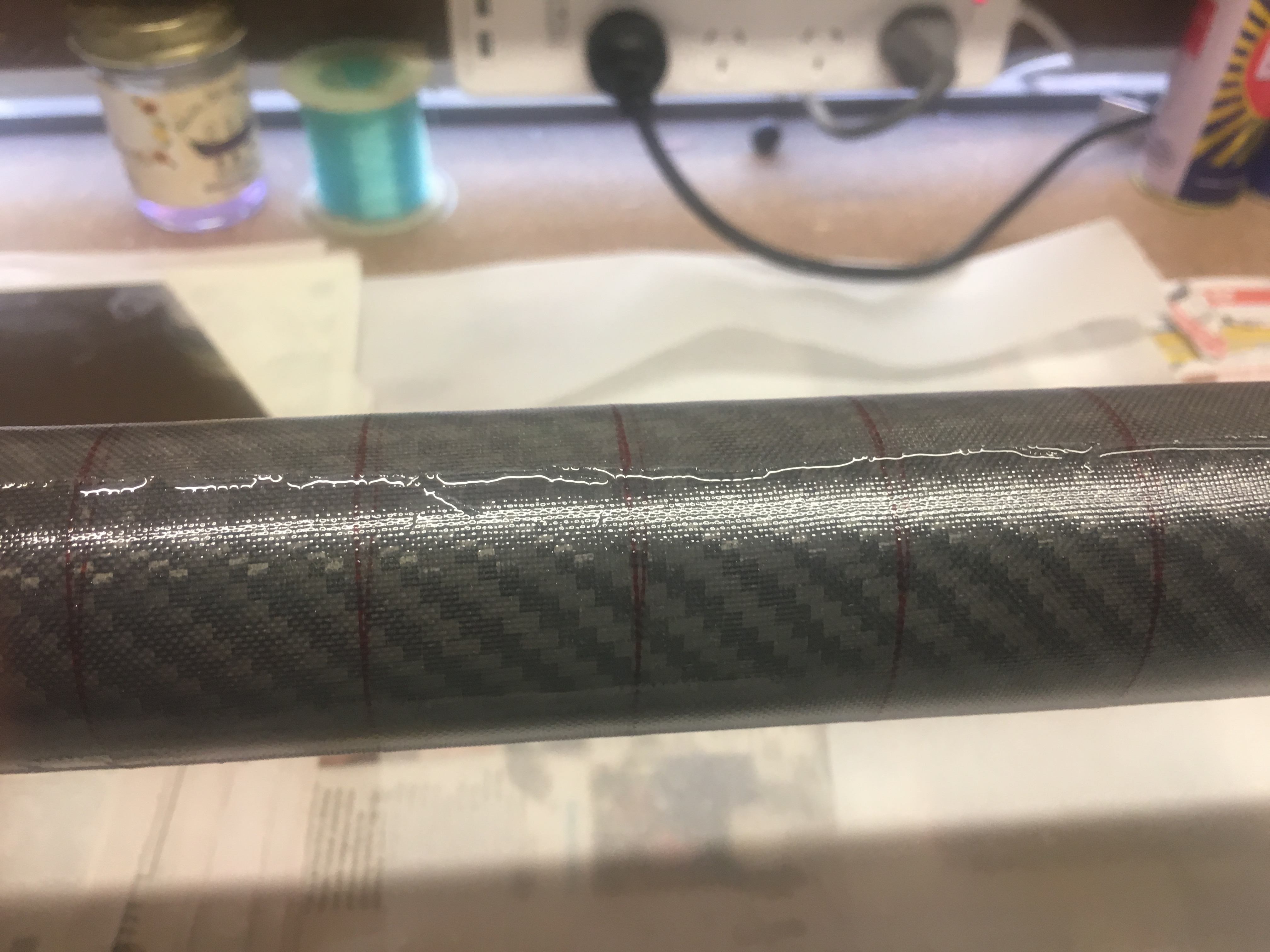
The Carbon Fibre fabric
The fabric I used is Twill 2×2. It is a weave that a lot of other people use.
Then I cut the Carbon Fibre fabric from the 5meter roll. I took GREAT care when doing this work. I did this all on the ground and because tidiness is so important, I vacuumed the ground before hand. I then measured out the fabric to look like the following.
Shape of fabric cut out.
After it was cut, I weight it. It came in at 83 grams. You will notice that on the right side, the fabric is a bit wider. This is so the base of the air-frame is slightly greater diameter, so the rear closure is smaller diameter than the Air-frame. This will make two stage (where this is the second stage) a lot easier.
The epoxy
I used K3600 Renlam epoxy. I made three lots of epoxy because I ran out. Batch sizes were:-
132grams
40 grams
35 grams
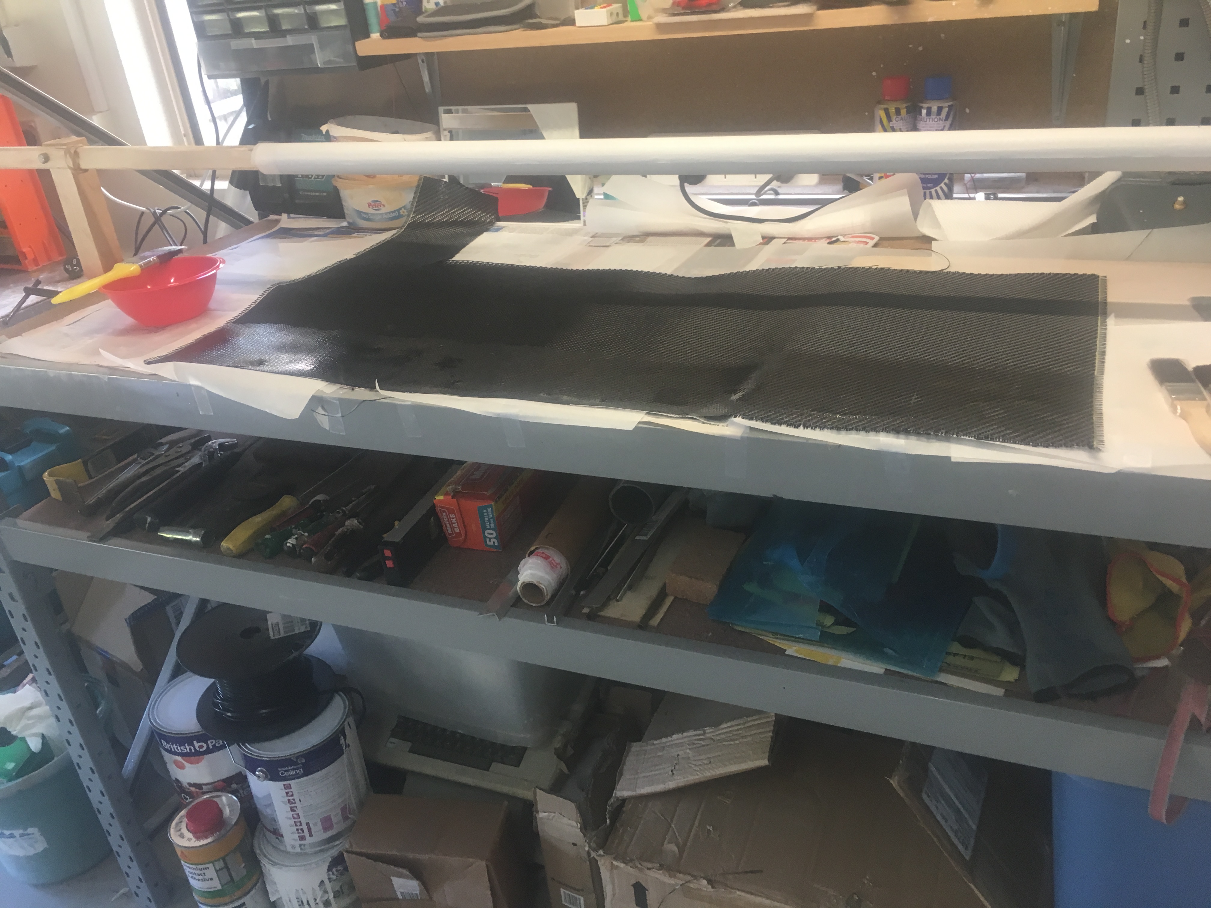
After making the first batch, I wetted out the first 120mm of the CF fabric. This was done to minimize dry spots that appear. And it worked!
Close up examination of CF fabric with epoxy on it. Here I’m checking for any dry spots.Carbon fibre – first 120mm all wetted out.
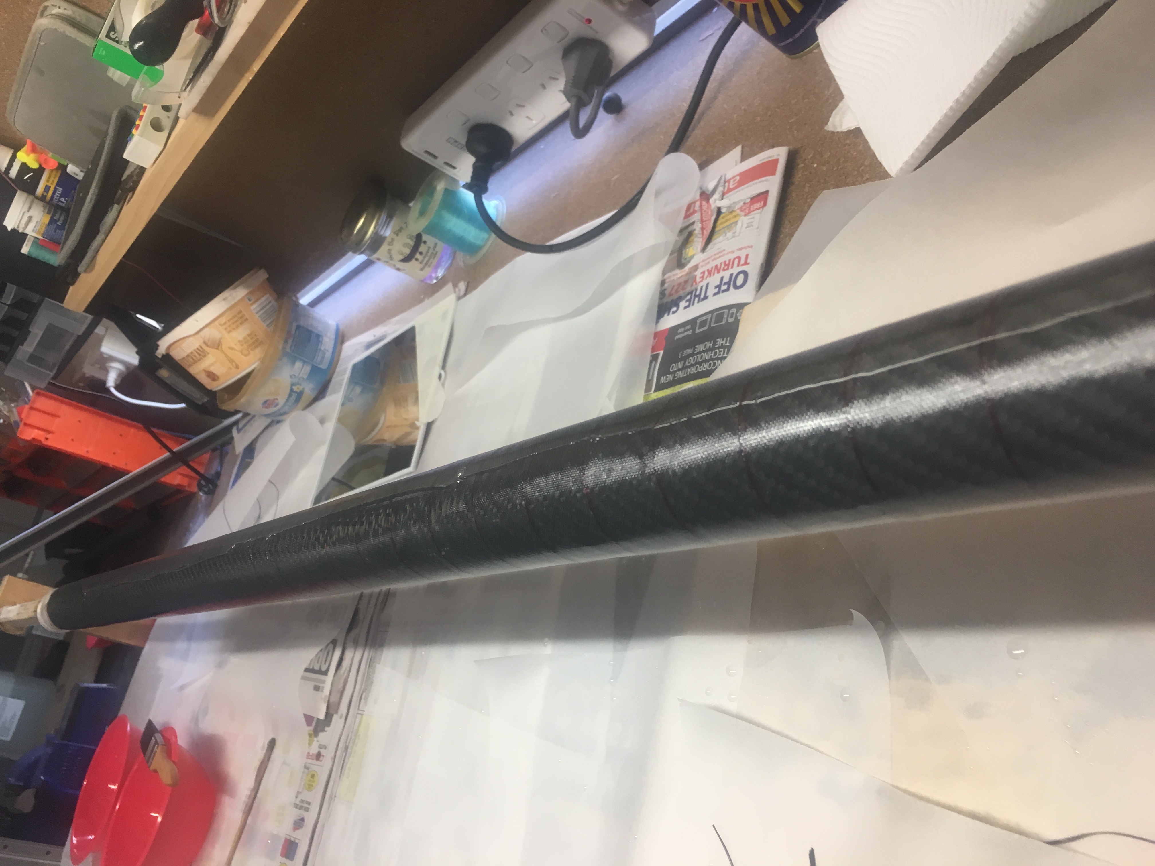
The CF was sticking to the Glad Bake I had carefully laid out on the bench beforehand, but I was able to pull it away from the Glad Bake and put it on to the Mandrel. It took a few goes to get it all lined up on the Mandrel. Not an easy process. Then I was able to start applying more Epoxy.
Examining back of tube during rolling.
I spent a fair amount of time examining the tube after the rolling. I wanted to make sure I hadn’t missed anything.
Examining job after applying Peel Ply. Close up.
Examining job after applying Peel Ply.
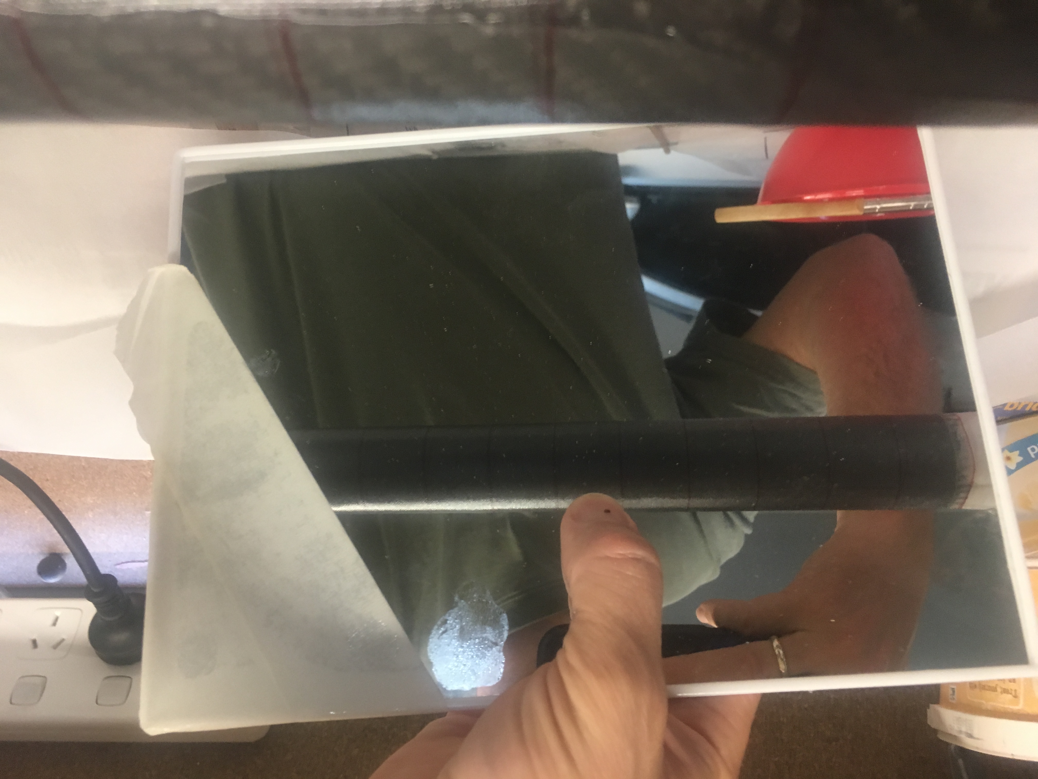
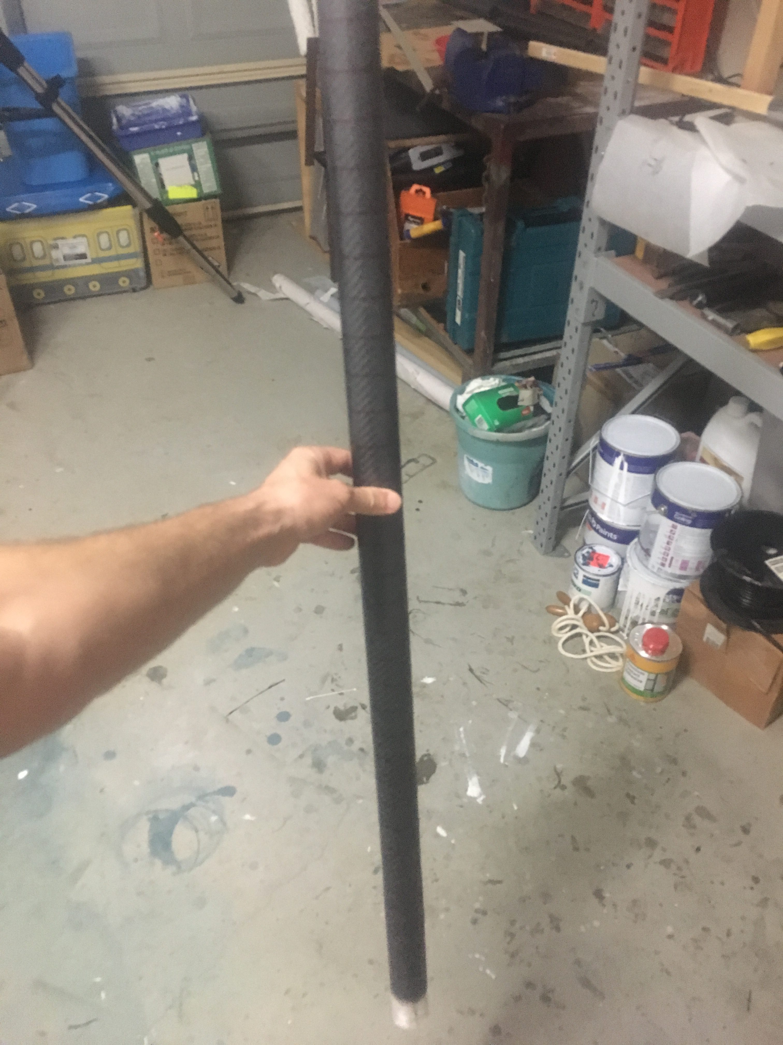
Removal of the Air-Frame.
That evening (23:00), 12 hours after applying the Peel Ply, I removed the Air-frame off the Mandrel. It was quite easy. I removed the Glade Bake and I then removed the Peel Ply. The Glad Bake stuck to the inside of the air-frame, but I was able to tease it off with a piece of aluminium right-angle. I did a test fit of the motor casing. It fit well!
Tube mostly cured. Need to remove Peel Ply.
Then I set it aside in my office in vertical orientation to cure for about 48 hrs.
I am using a Pico AA2 Altimeter and I wanted to run a few tests:-
Test that the Altimeter seems to work – i.e. will detect launch and can detect Burnout and then Apogee. I do this test because I wouldn’t want to fly with a faulty Altimeter
Test that the Altimeter with the 2 x 3.7v 180maH LiPO batteries can supply the current required to fire two e-Matches one after the other
Test the Cable Cutter and the procedure to set it up.
The Set-up
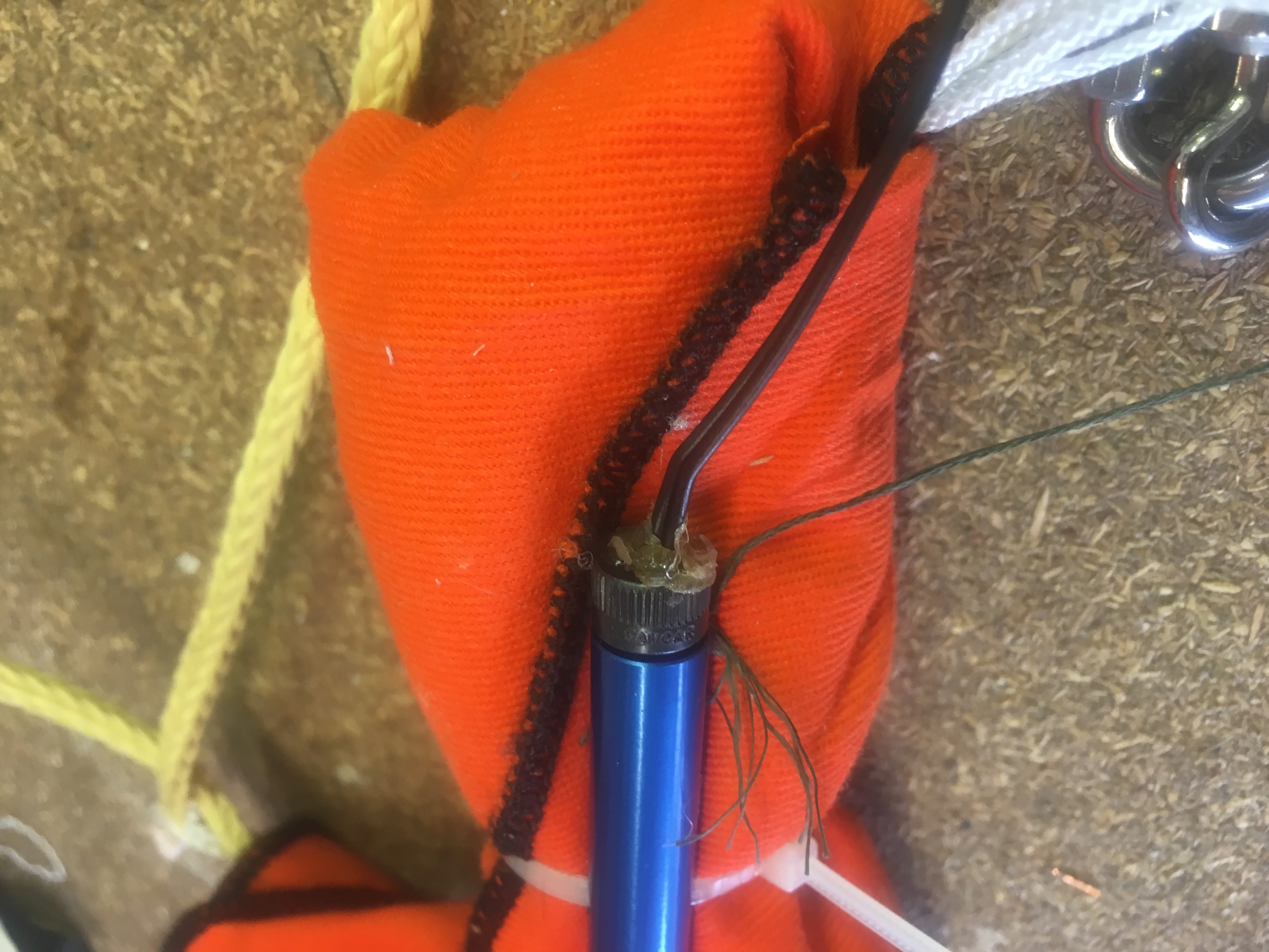
Here are photos taken during the set-up.
Igniter already threaded through cable cutter closure.Tape put around the igniter, to reduce chance of shorting against the Cable Cutter case.Hot Glue to keep the black powder in.All the igniters connected.Everything connected.
The Results
Here are the results
Detection of Launch Events
Data from “test” launch on bench
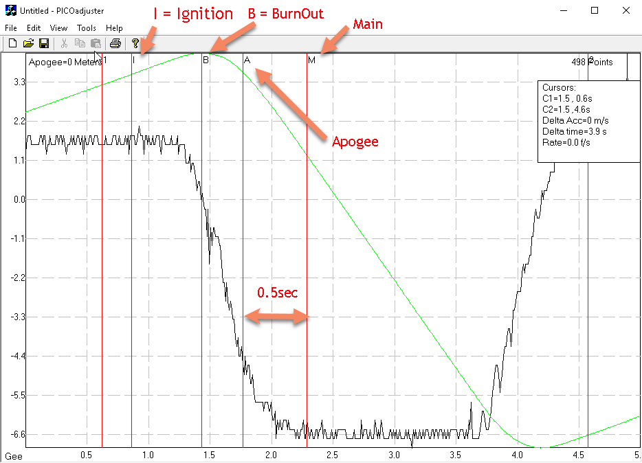
We had the Pico AA2 pointed up while it was configured with 2G = 8 which is equal to about 1/4g. Because the G’s are more than 0.25g, the Pico AA2 thinks it has detected launch.
I then turn the Pico so that it is horizontal. As I do this, the G’s pass through zero, which it takes a motor BurnOut. Then it looks at the area under the curve as the rocket “deaccelerates” and when this area is equal to area under curve between Ignition and BurnOut, it then assumes we have lost the velocity we gained; i.e. we are at Apogee. So it fires the Apogee (A) event. Then, because we are below the 800ft, it fires the Main 0.5 seconds later.
Apogee
This will ignite black powder that will separate the top section of the rocket (including the nose cone) from the main air-frame. In this test, we just want to make sure the igniter does it’s job. Ignites.
The Main
Here we test that Main Output fires.
Conclusion
So I ran this test and I’m now fairly comfortable that the Pico AA2 works. I also observed both igniters working, which means the Pico AA2 batteries can be depended upon.
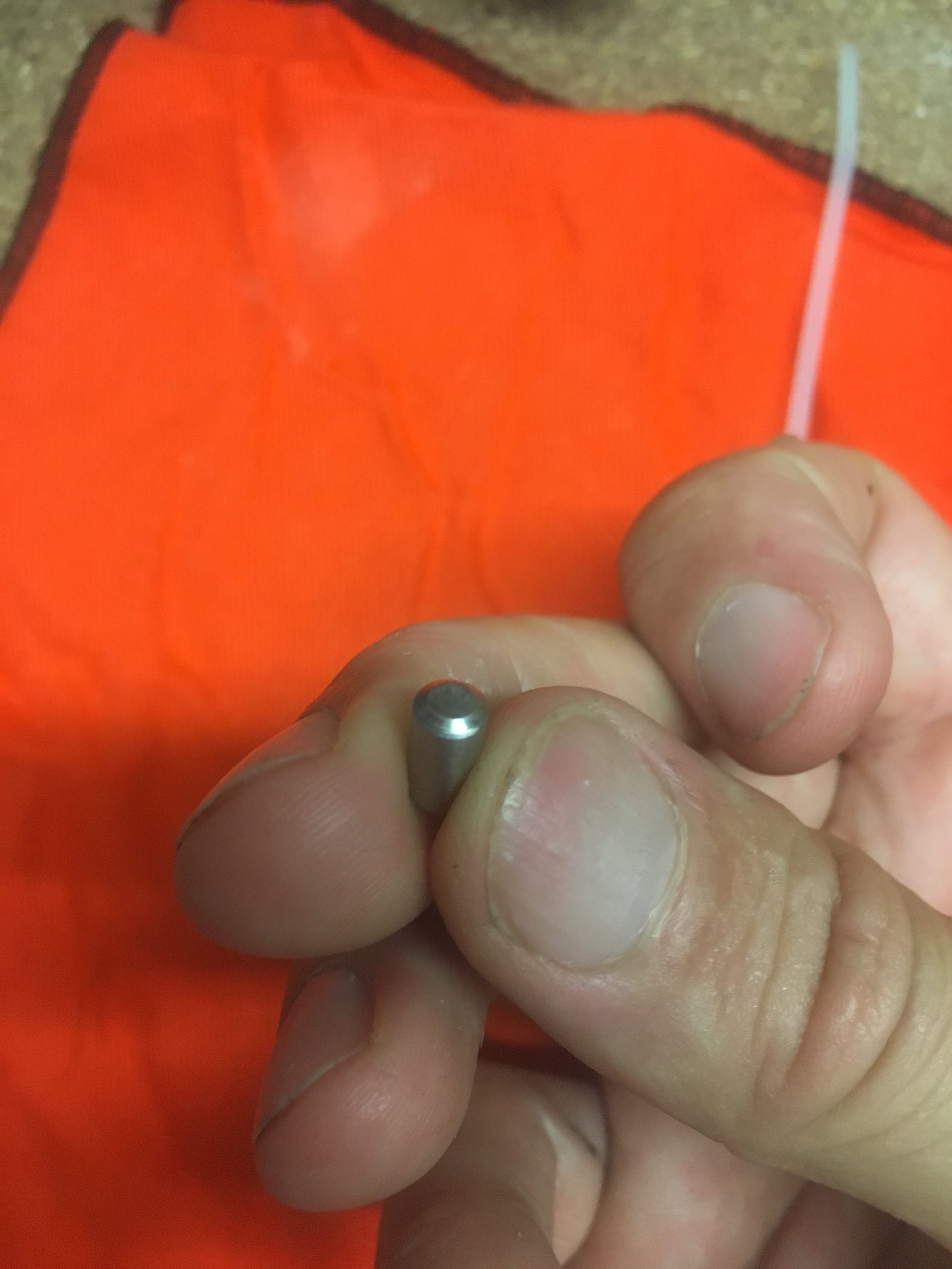
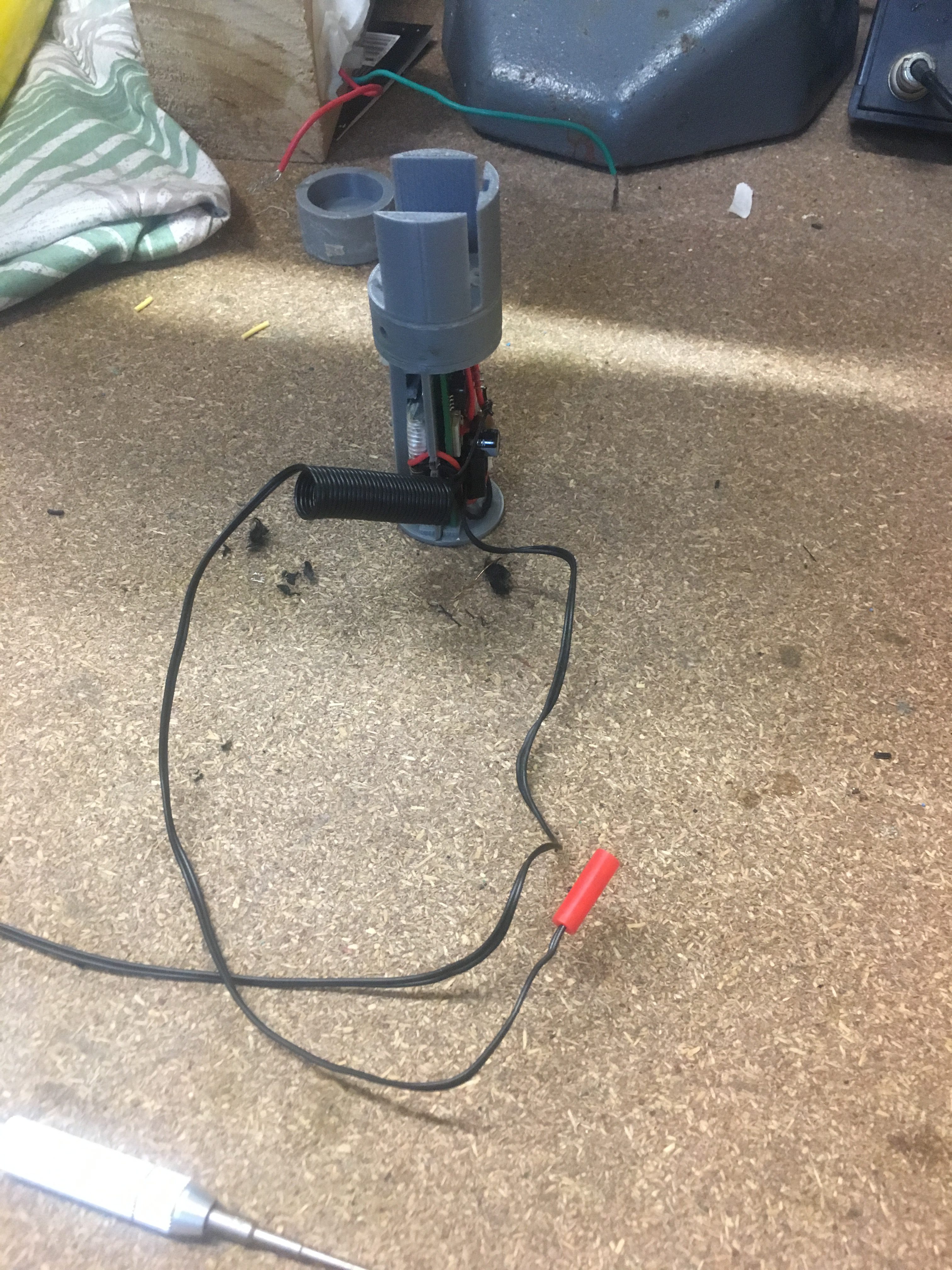
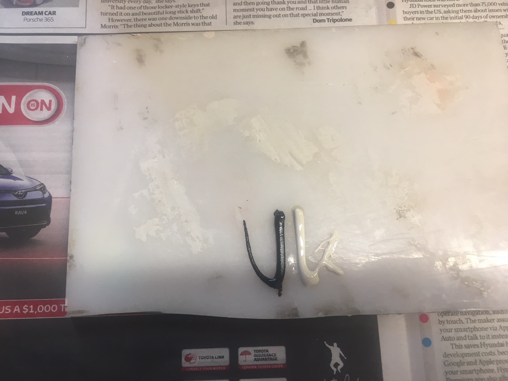
However, the Cable Cutter did not fire. I suspect this is because of two things.
The piston is a dud – it doesn’t have a “cutting edge” like other photos show
A significant portion of the black powder gas went out the back.
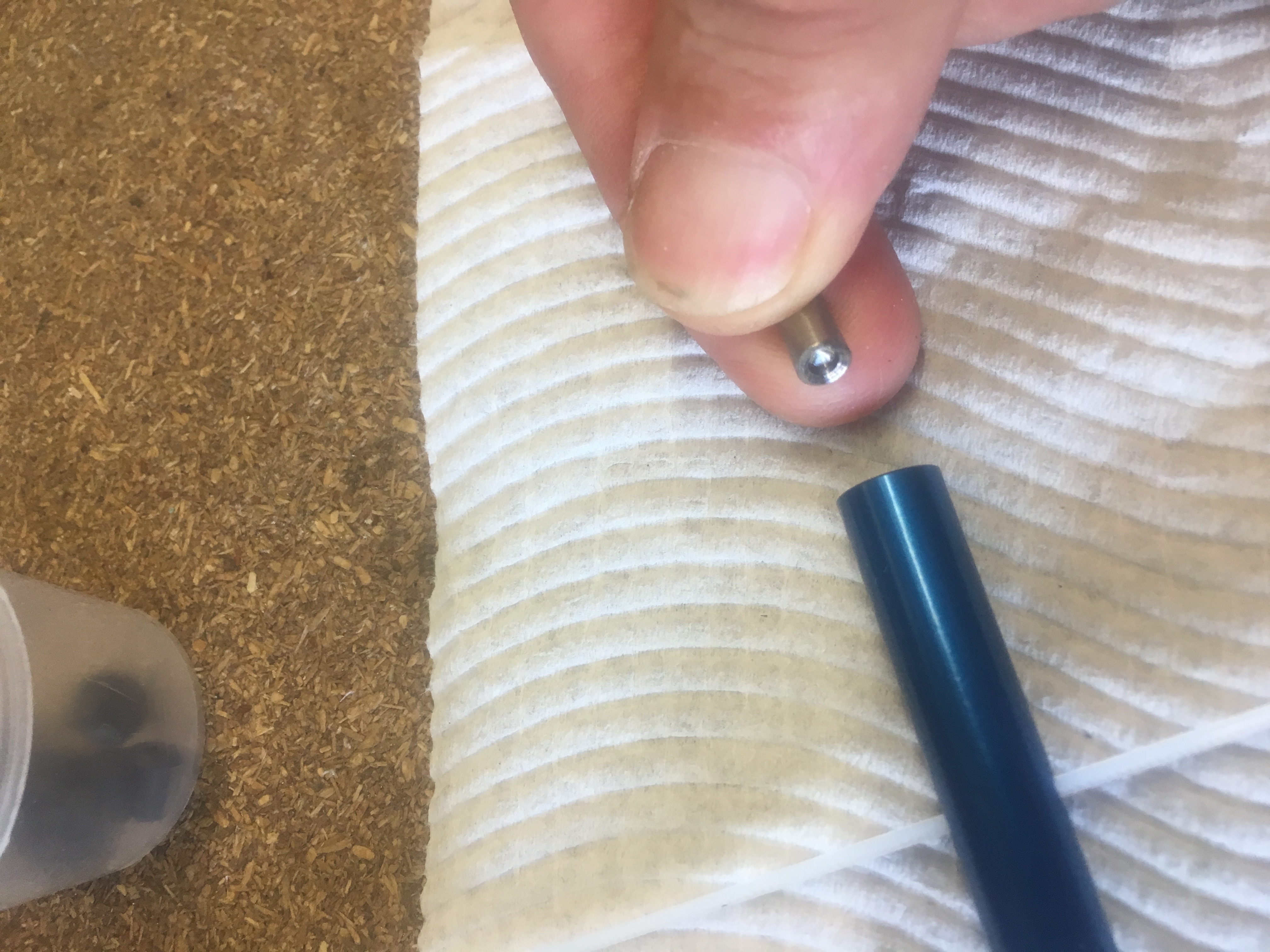
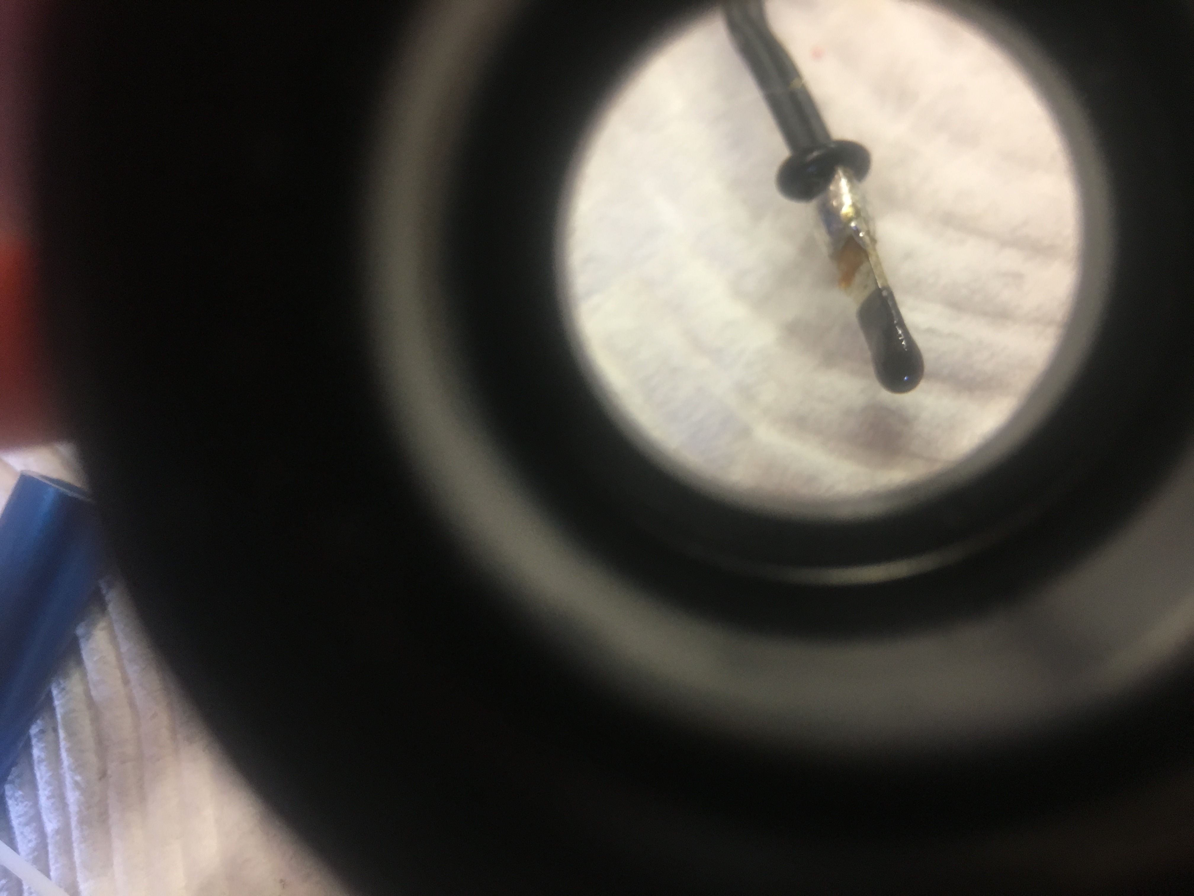
Here is a photo of the piston.
This should have a very sharp cutting edge…a concave hole.The piston seized up in the cable cutter body. This screw-driver shows how far it was stuck in.
The finish of the Epoxy on the CF air-frame wasn’t staying shiny/beautiful. Also there were a few imperfections that I wasn’t happy with. So I decided the best course of action was to apply a clear coat. I could then sand to 2000 Grit and polish it to perfection.
The Paint
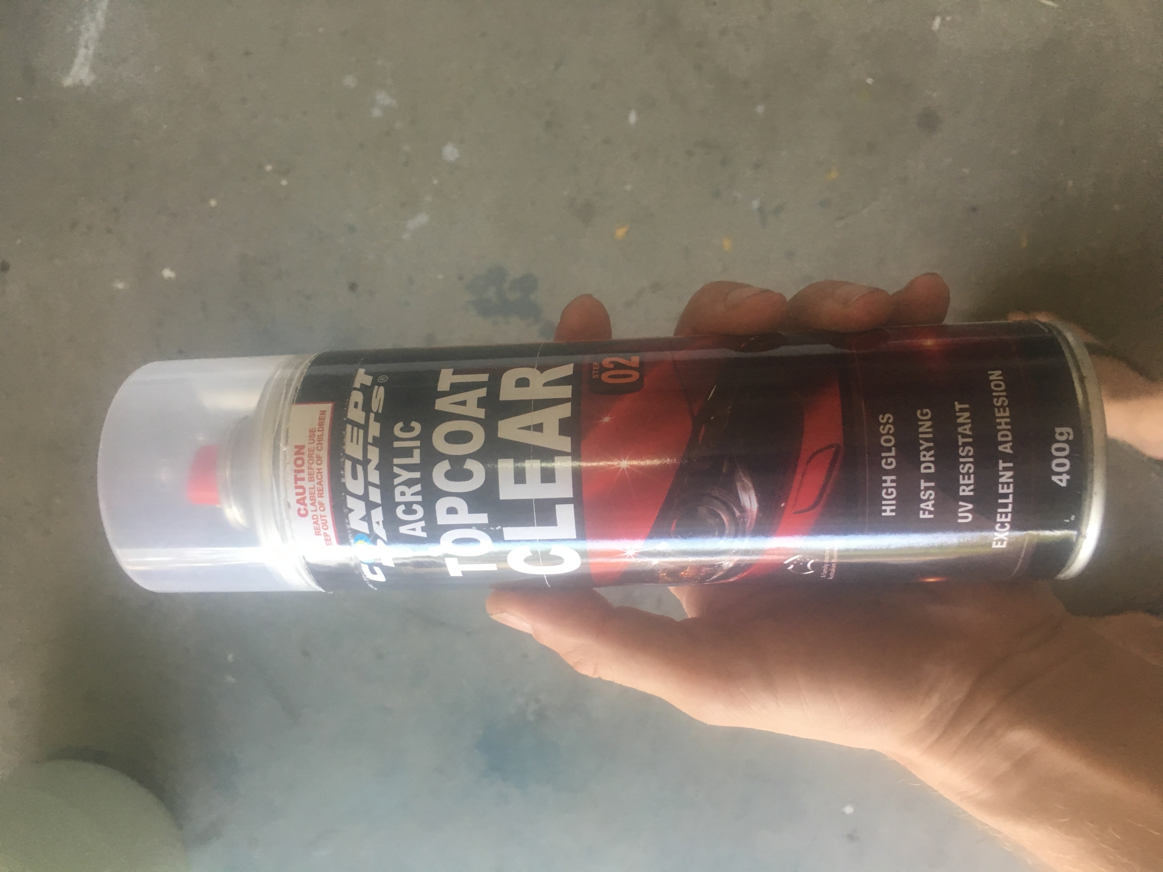
I used Acrylic clear coat from AutoBarn – a large can.
ClearCoat paint used.
The Test Run
I first did a test run on a piece of tube because I didn’t want to assume it would just work.
To my shock after a few coats of clear coat it looked terrible and I thought that I would have to forget applying a clearcoat until I found out what was a happening. I thought it was perhaps due to humidity, but I was advised by a friend that you might have problems with rain, but humidity should not cause what I was seeing.
So I decided to sand it from 1500, then 2000 and finally 3000 before polishing.
The test tube comes up looking really good after sanding 1500,2000,3000 and then polishing!
Thank heavens!
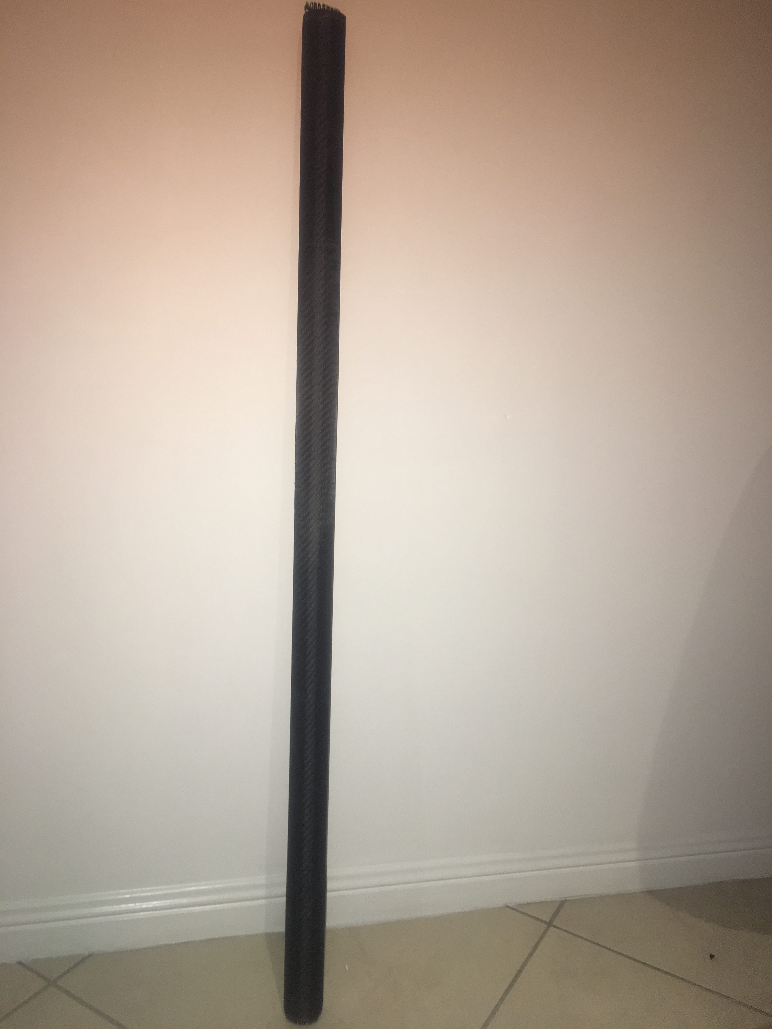
The Real Run
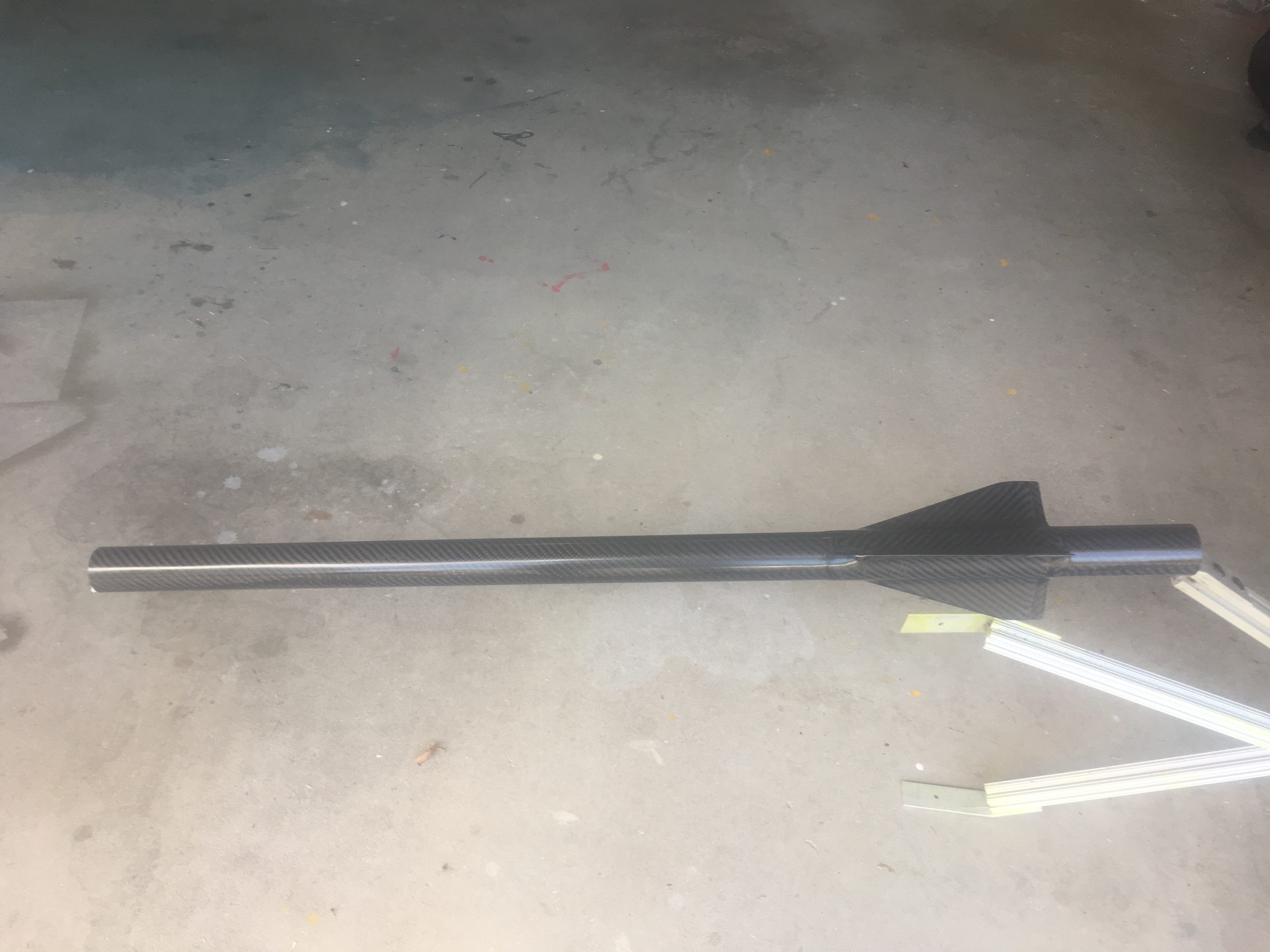
I then proceed to apply clear coat to the rocket. I applied 4 coats. Below are some photos I took.
First coat of clear done.Rocket after several coats – starting to lose the gloss look…for now.
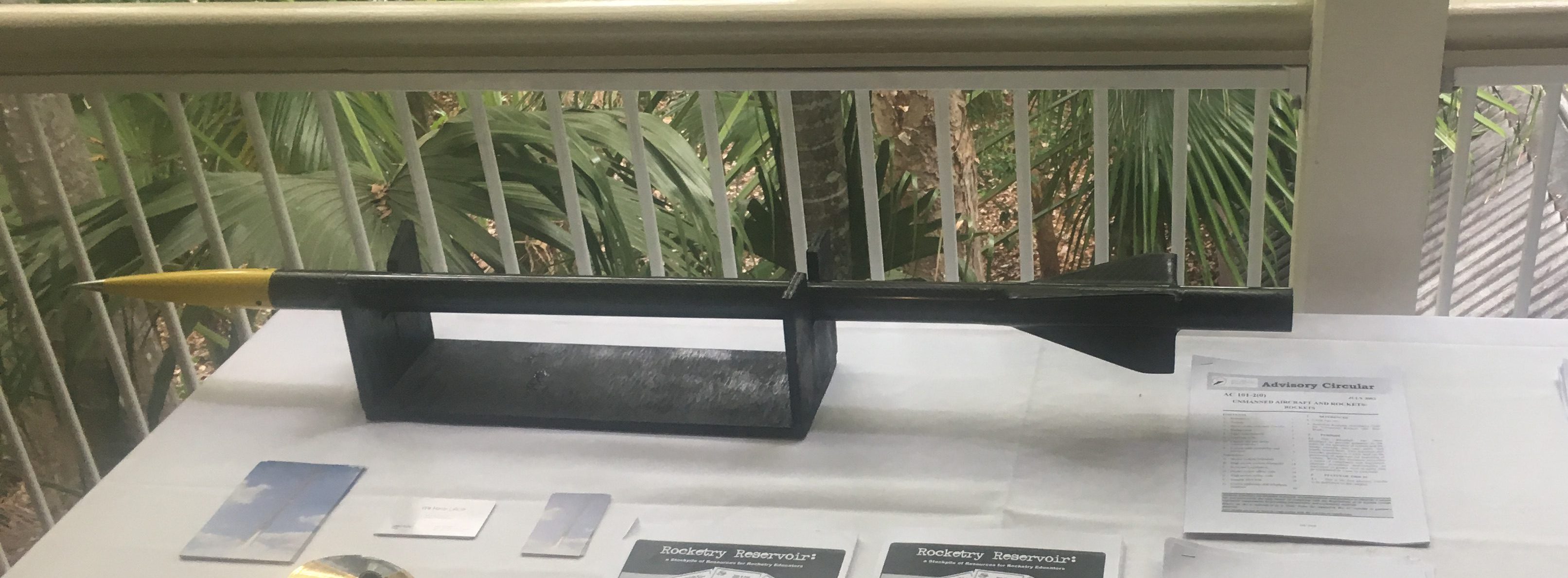
Here is photo of it looking splendid at a presentation of my rockets.
Rocket after sanding and polishing. Looking Splendid.
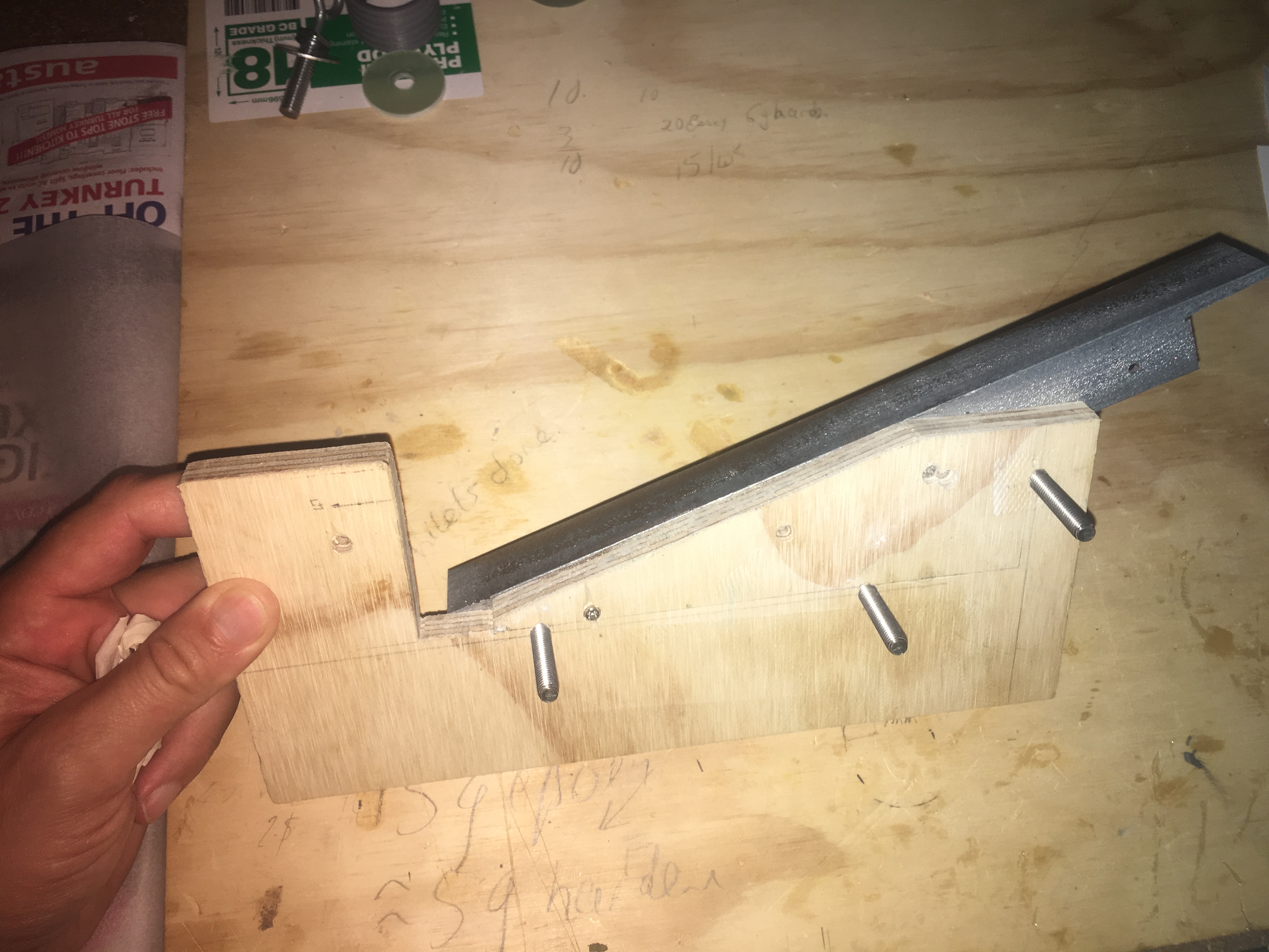
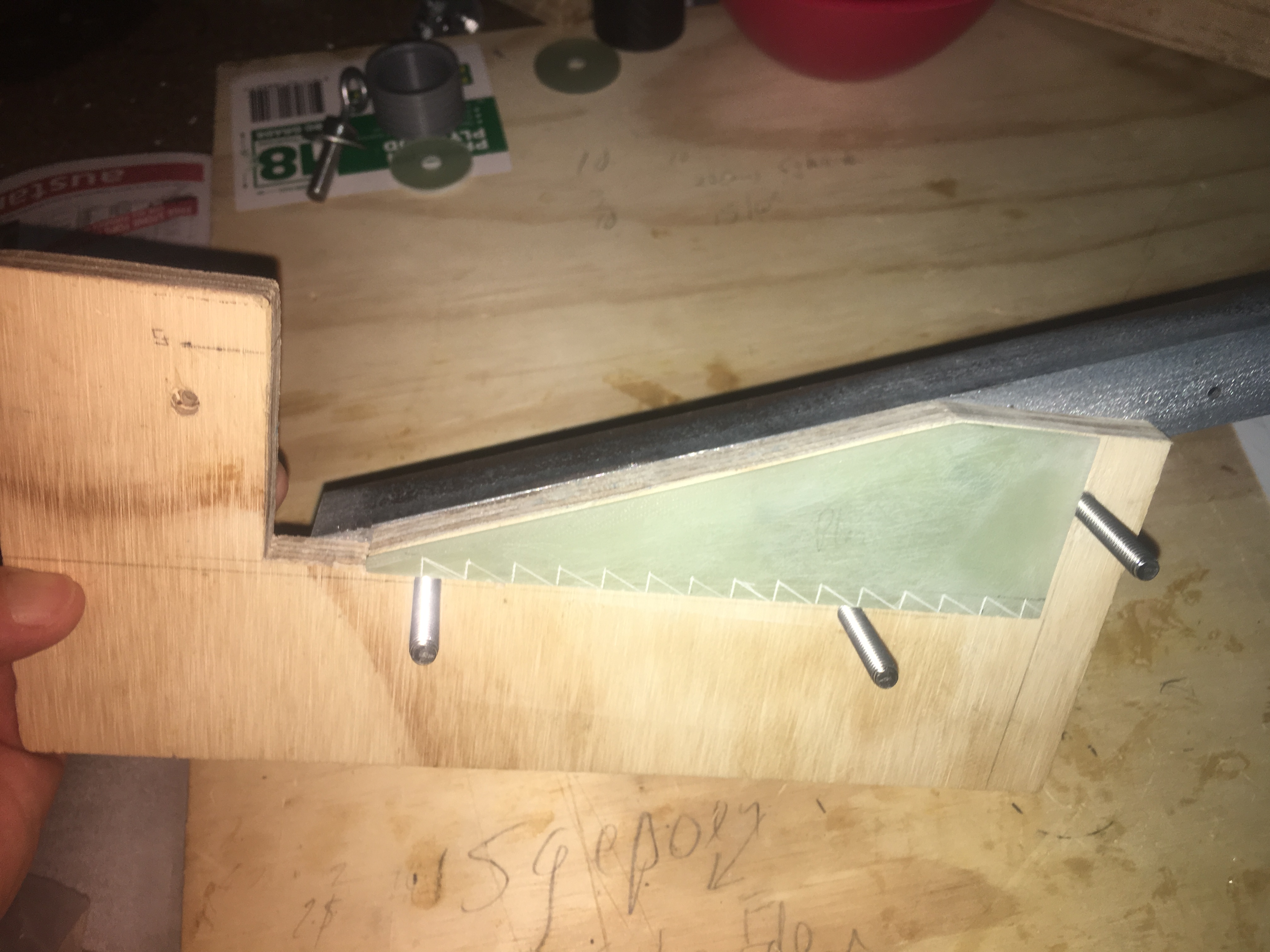
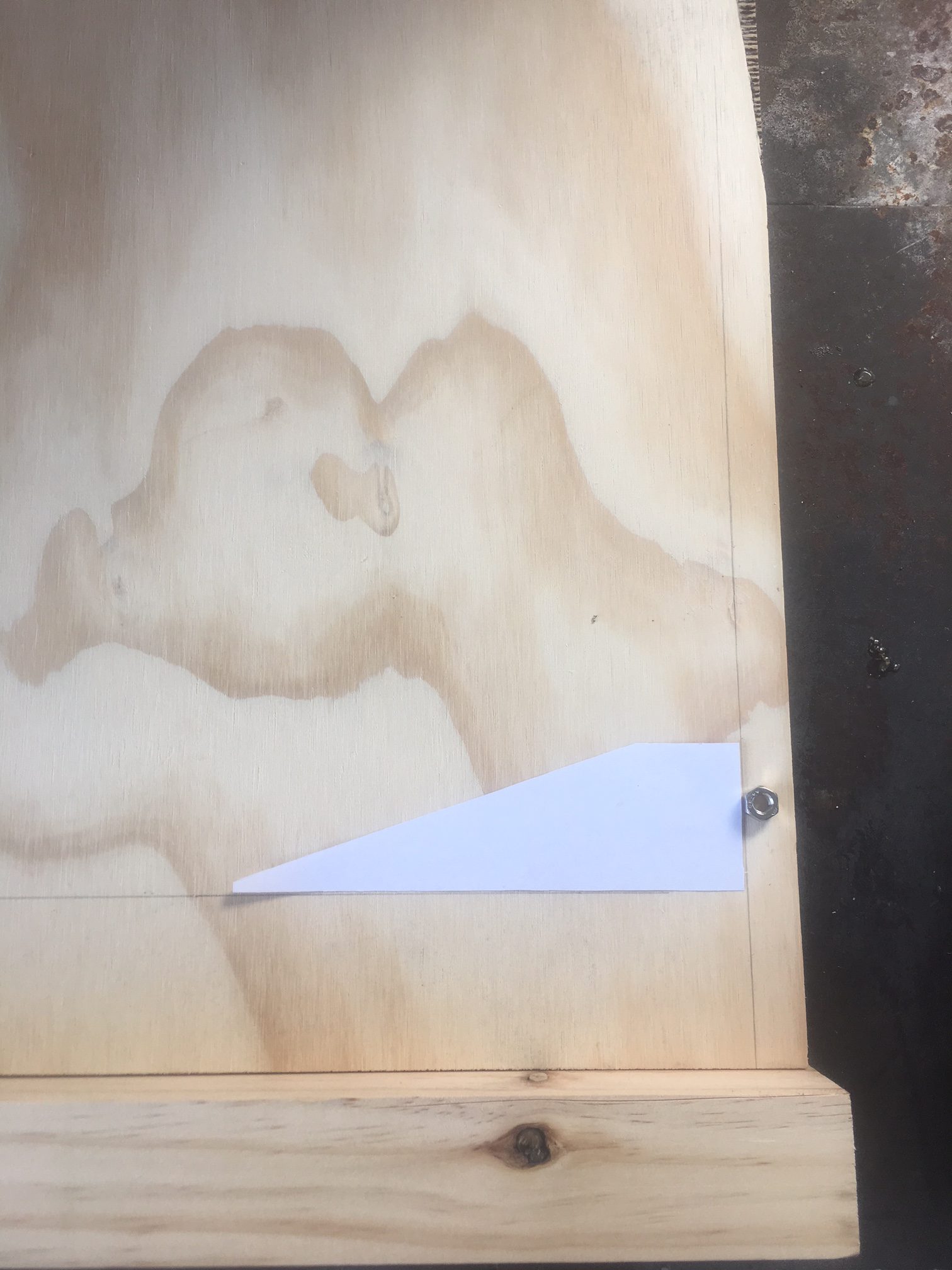
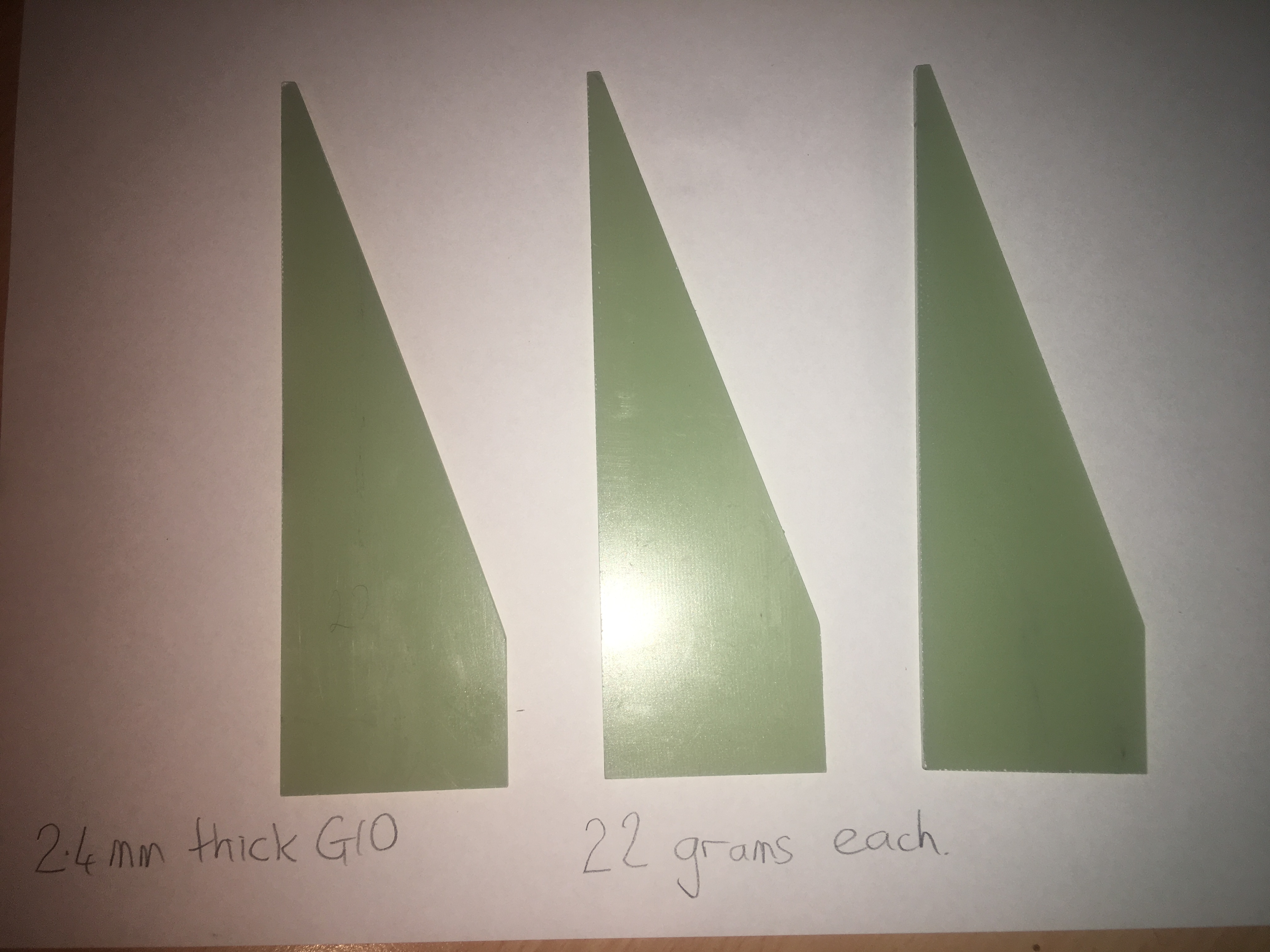
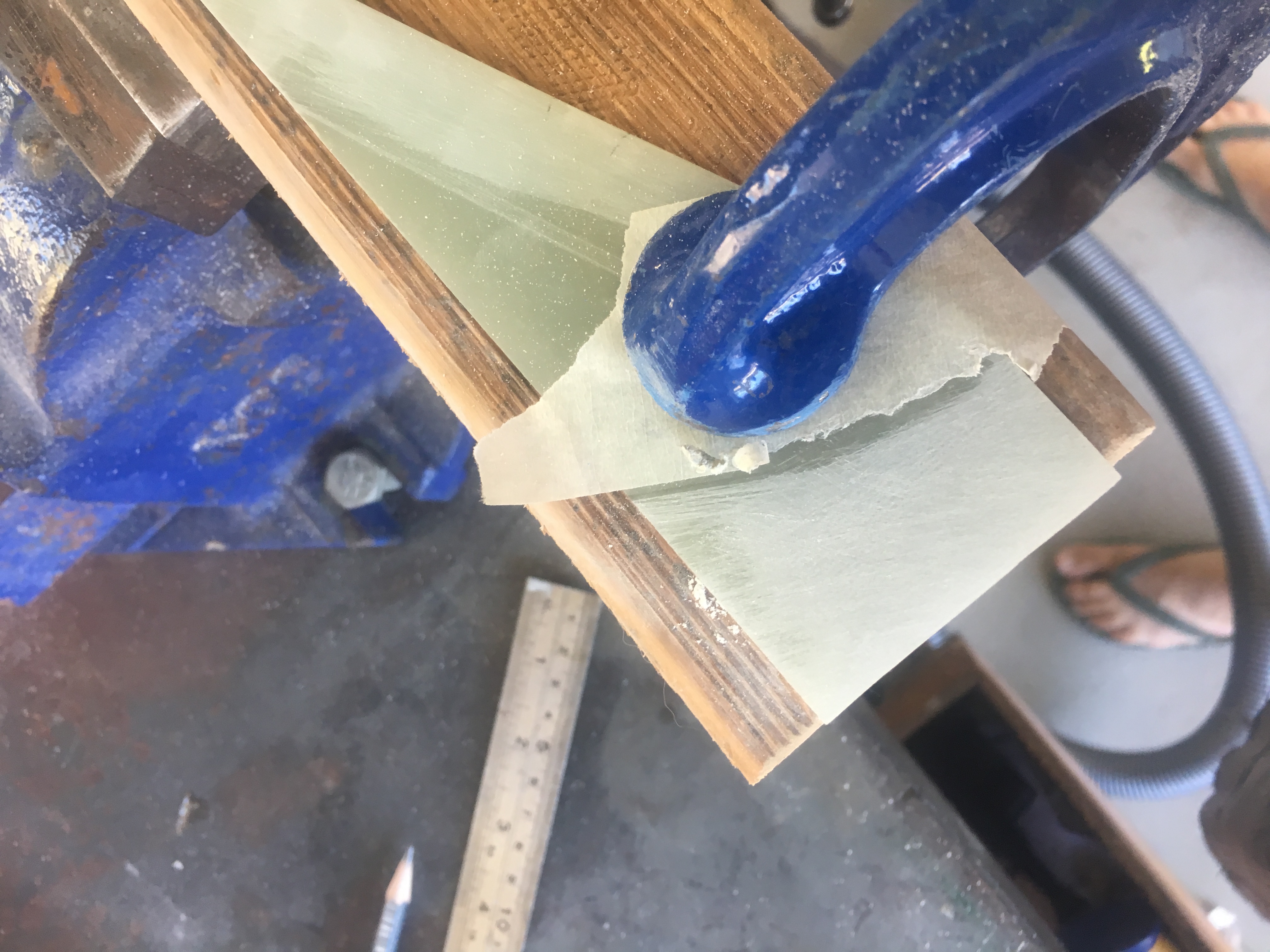
The fins are created from 2.4mm thick G10 plate. I created a clipped delta design and created a jig that I would use to sand the three fins down to the correct IDENTICAL size. Below is a picture of this jig.
Jig with nothing in it. Right angle Iron back is what we use as a guide when sanding.Jig with Fin it. We use a G-Clamp to hold it in place.
I have used a Steel right-angle bar to sand up against. Here are some pictures of the fins.
Cut-out to give us approx dimensions to cut the G10 material.All fins cut out and sanded using the jig and all identical.
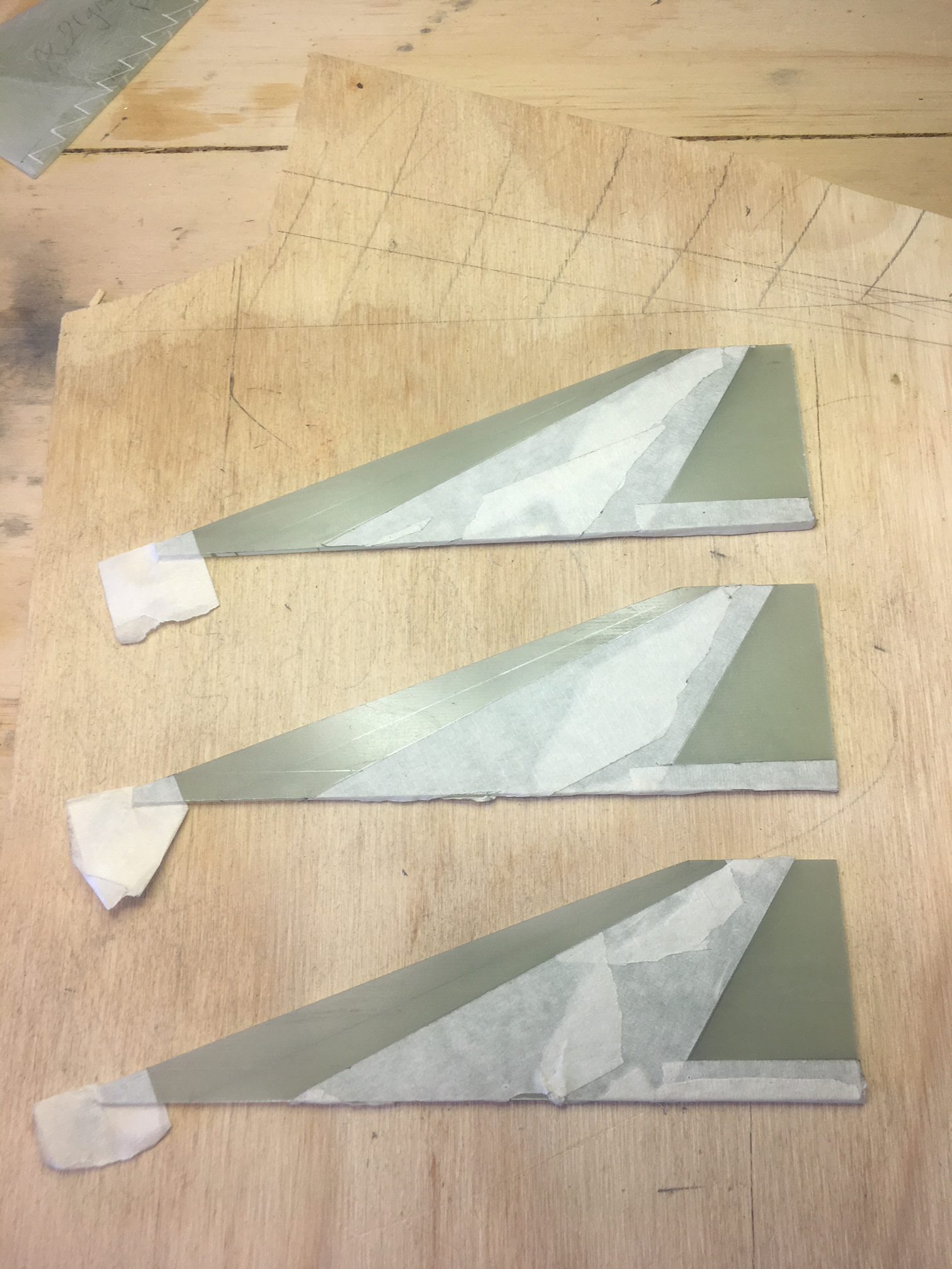
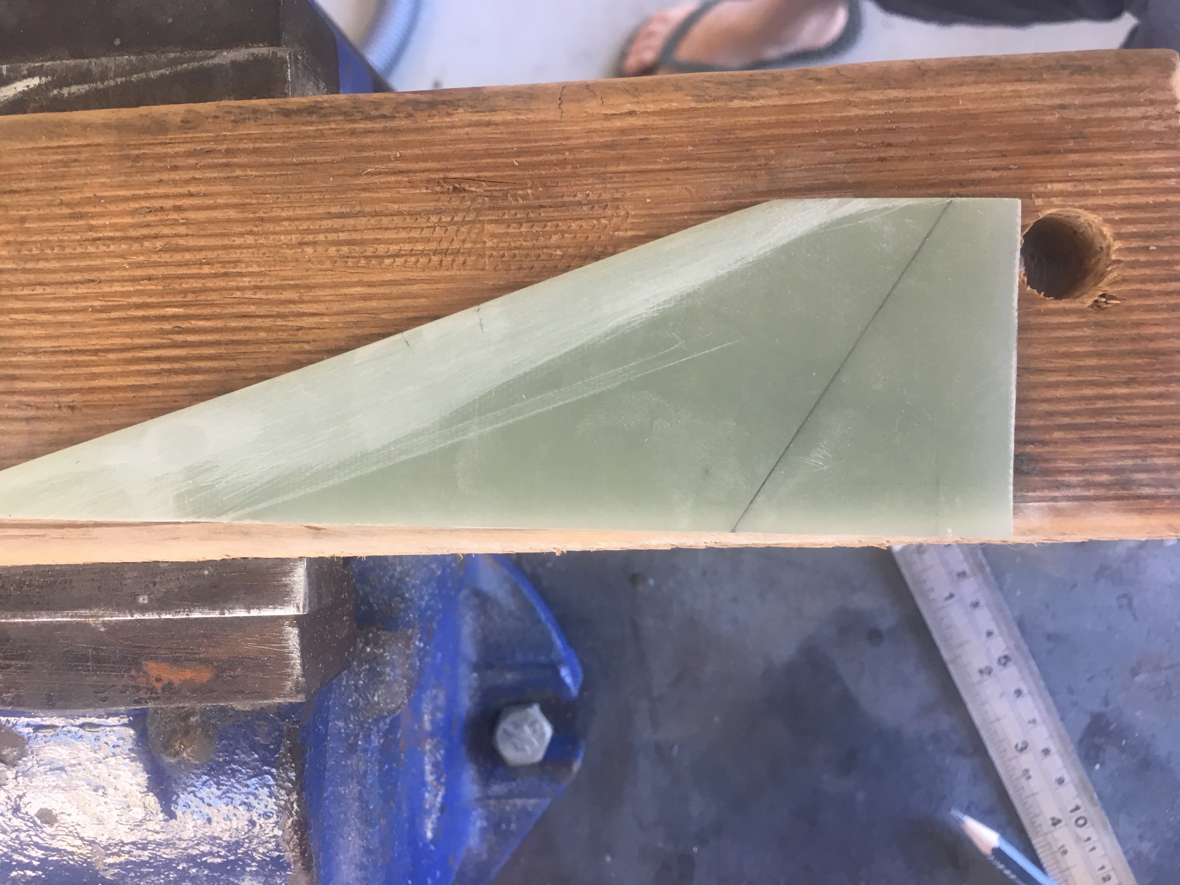
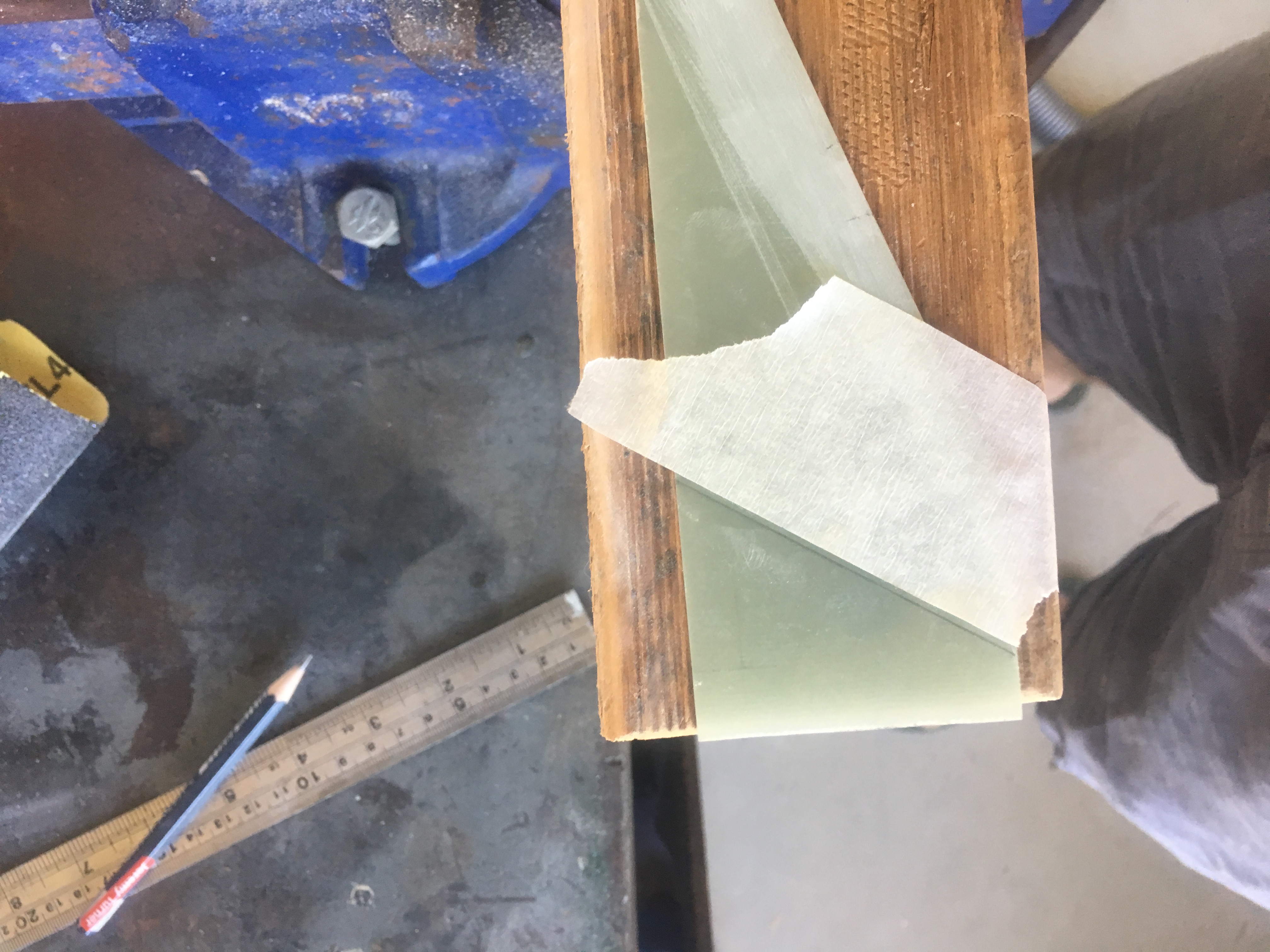
Profiling the fins
I wanted the fins to have a profile suitable for less than speed of sound. While they will travel greater than speed of sound for some motors, for the majority of the flight they will be travelling below the speed of sound. I also choose this design because it is relatively simple to produce.
Taped up ready for sanding. Areas taped are the areas we do NOT want sanded.
I did all this work by hand. I started by drawing the boundaries of the sanded regions. I even drew a line down the thickness (half way) on leading and trailing edge.
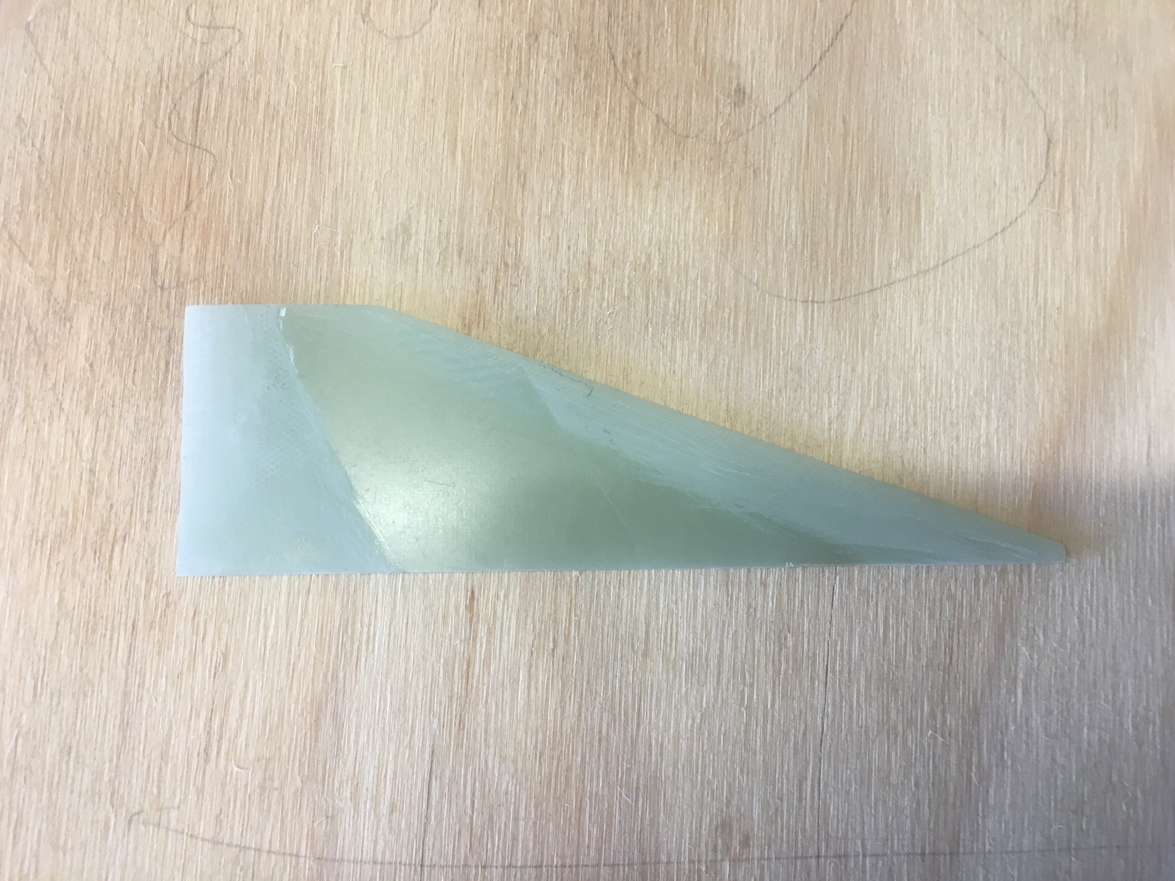
Here are a tonne of photos showing this process.
Carefully sanding the rear of the fin.Carefully sanding the forward section of the fin.Reviewing the sanded surface.Carefully sanding the rear of the fin.
Surface Preparations for Epoxy
It is very important to do all fin preparations BEFORE we attach them to the air-frame; it is a lot easier to do.
I sanded the entire surface of the fins with Grit 60 sand paper. This is so that the epoxy fillets adhere well to the fins and also so the CF Fin-to-Fin material adheres properly.
Little cuts were made on the root of the fin every 10 mm, approx 1 mm deep with a hack-saw to encourage a good bond to the air-frame.
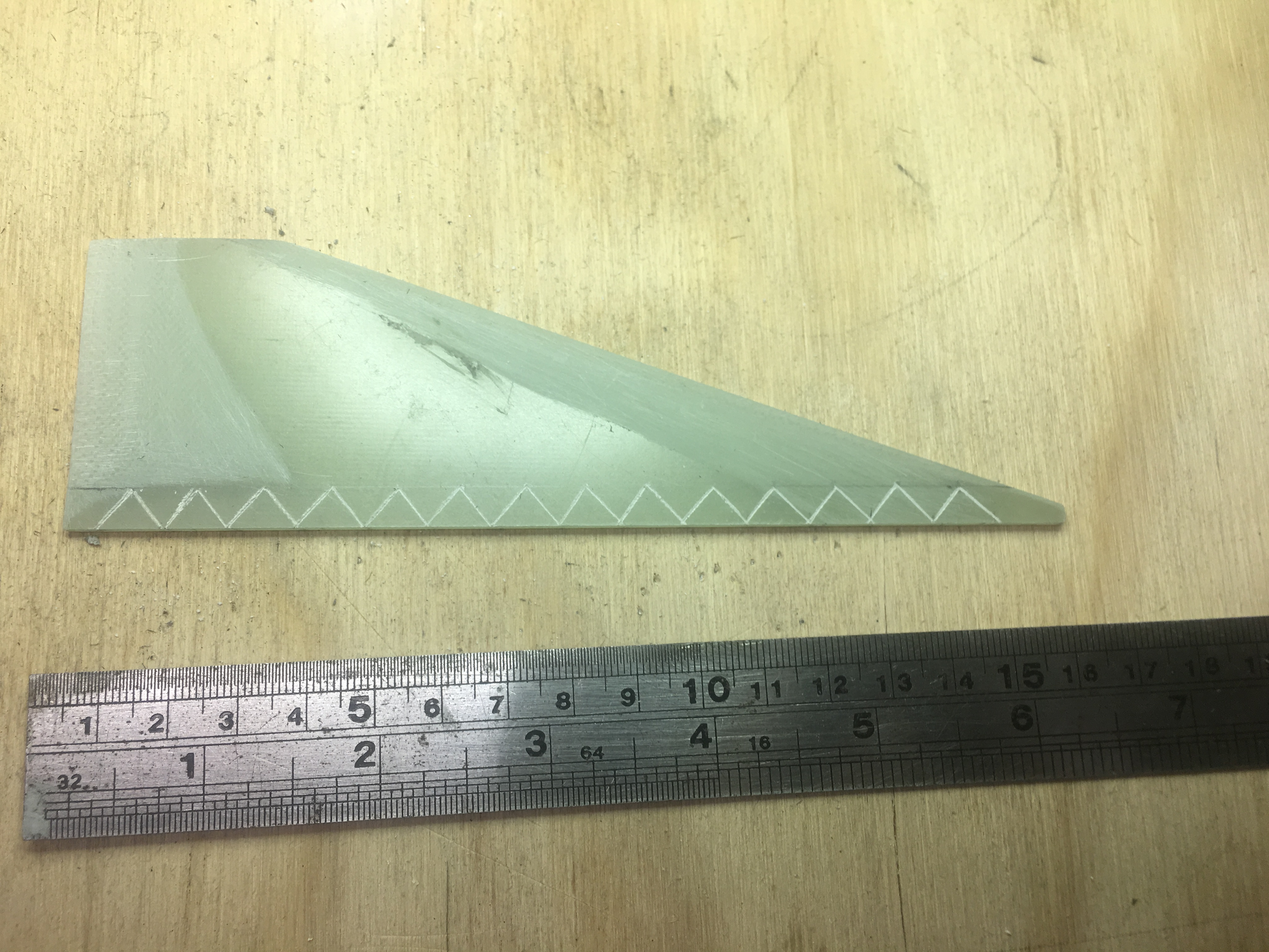
I also scribed 45 degree incisions every 10 mm from the root, to ~7 mm up from the root. This provides extra place for the epoxy fillet to ‘grab’ on to the fins. I used the following “tool” to do this.
Tool I made to score the fins.
Here is a photo of one of the fins I scored.
45 degree scoring of the Tang of the fin.
I also used a hack saw to cut 1mm deep incisions into the root of the fin every 10mm. No photo available.
I created some jigs using my 3-D printer to hold the fins in place. I had a few goes at getting ones that would slip on easily…but not too easily. This is so the fins could not flop about.
Two jigs to hold the fore/aft section of the fins.
You may wonder how I avoided JB-Weld getting on to the Jig. Well, I have a gap between the air-frame and the inner surface of the Jig. So I was able to carefully insert the fin with minimal or no JB-Weld getting on the jig. In some cases the fin did stick a little to the 3-d print, but it was easily pried off.
Attaching the Fins
I used JB-Weld Epoxy to attach the fins, just like I did for the previous rocket build. I didn’t have the luxury that I had then of being able to see through the air-frame to look at the adhesion of the epoxy. But that is okay. I only attached one fin at a time, giving it 24 hrs for the epoxy to cure.
Photos
Here are some photos of the process.
Laying out equal amounts of JB-Weld components.Thoroughly mixing the JB-WeldApplied JB-Weld to the fin root.Seated the fin into position.
I created the fillets using West Systems. The products used were:-
105 Epoxy
206 Hardener
413 Filler (this supersedes 403 filler)
Masking tape
Tool used to shape the Fillets
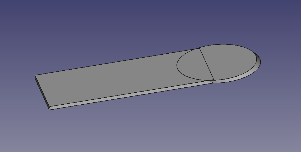
I created a special tool (pictured below) to help shape the fillets. This tool was created using my 3-D printer. It was shaped to give a fillet of radius approx 6 to 7mm.
Screenshot taken in FreeCad of tool
The tool was created in FreeCad using a cylinder of radius of 7mm sliced at 45 degrees and attached to a “handle”. This allows me to drag the tool along the surface at 45 degrees, knowing that the curvature of the fillet is approx 7mm.
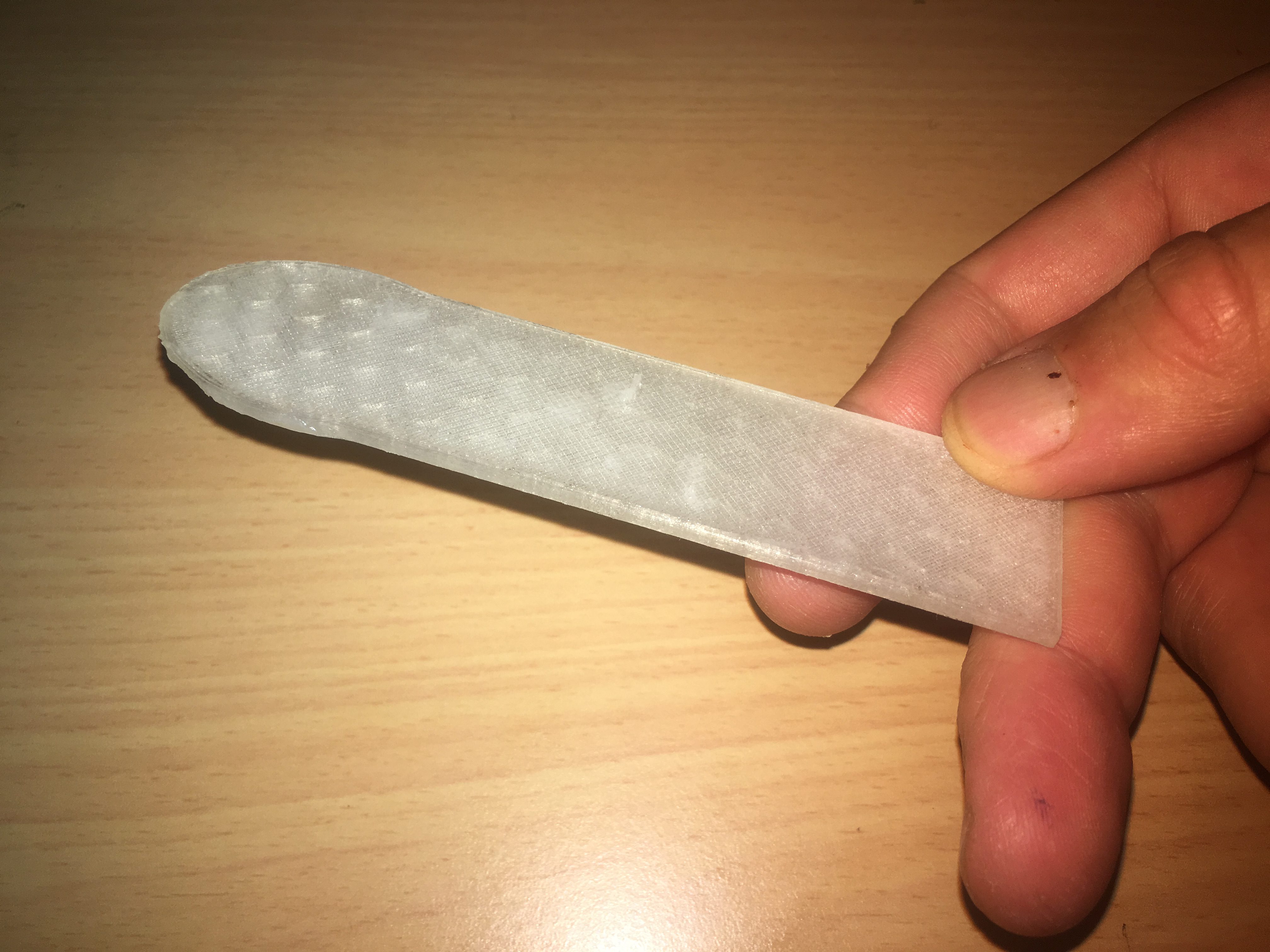
Here is a photo of it:-
Tool for shaping the fin fillets.
The Procedure
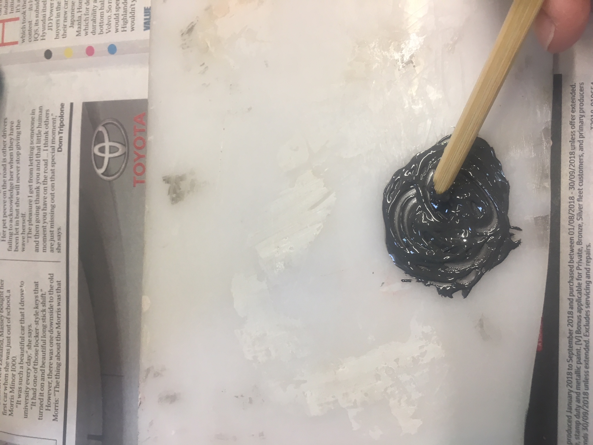
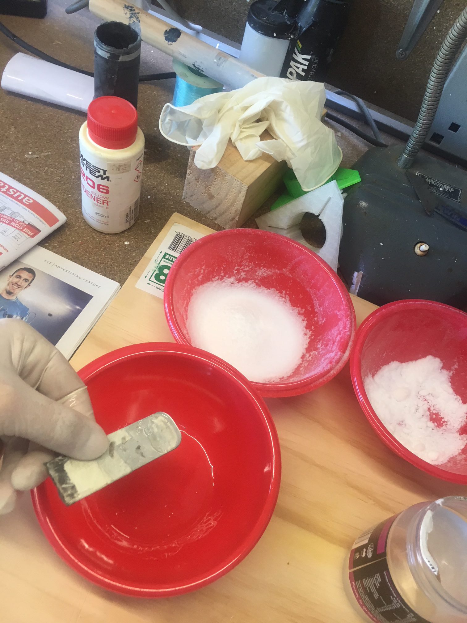
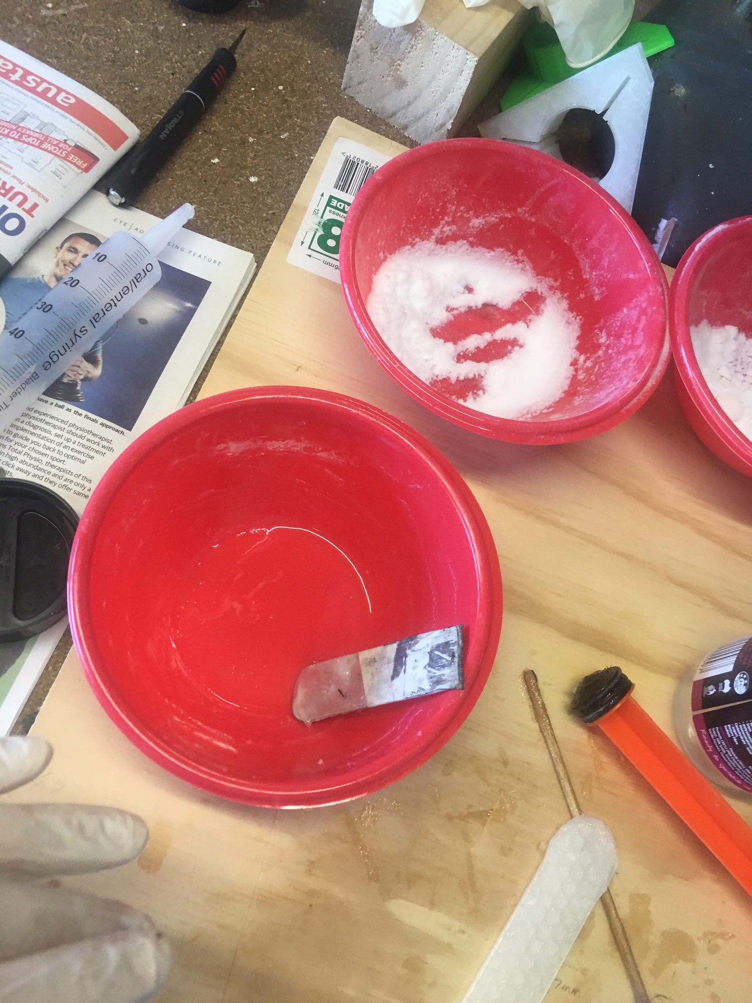
I measured 105 Epoxy and 206 Hardener materials by volume using a syringe. I passed the 413 through a sieve to remove the lumps. Then I introduced 413 filler in small quantities, until it’s consistency was that it JUST held its shape. Then I loaded this Epoxy into another syringe and squeezed it into the fin roots and shaped them.
Mixing up the EpoxyEpoxy/hardener thoroughly mixed.Putting prepared Epoxy into Syringe ready for use in rocket.
Creating the fillets
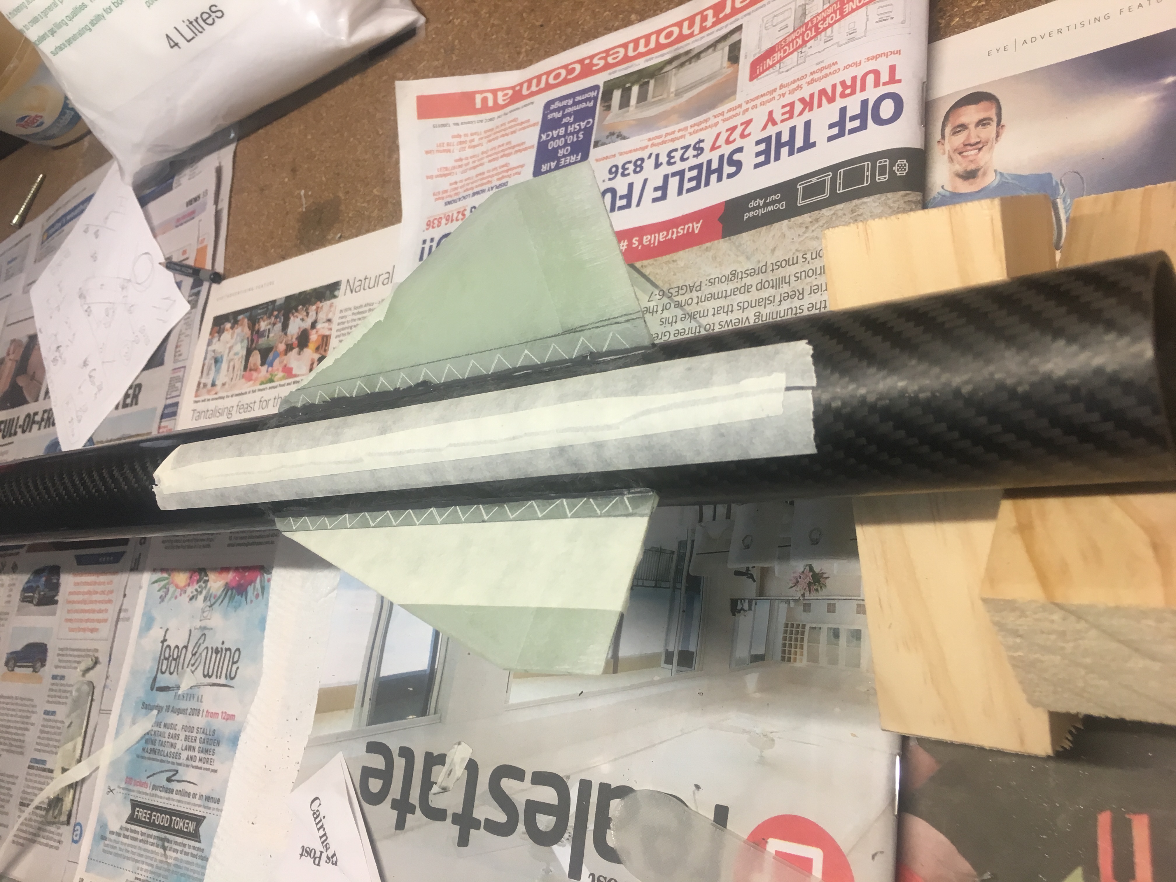
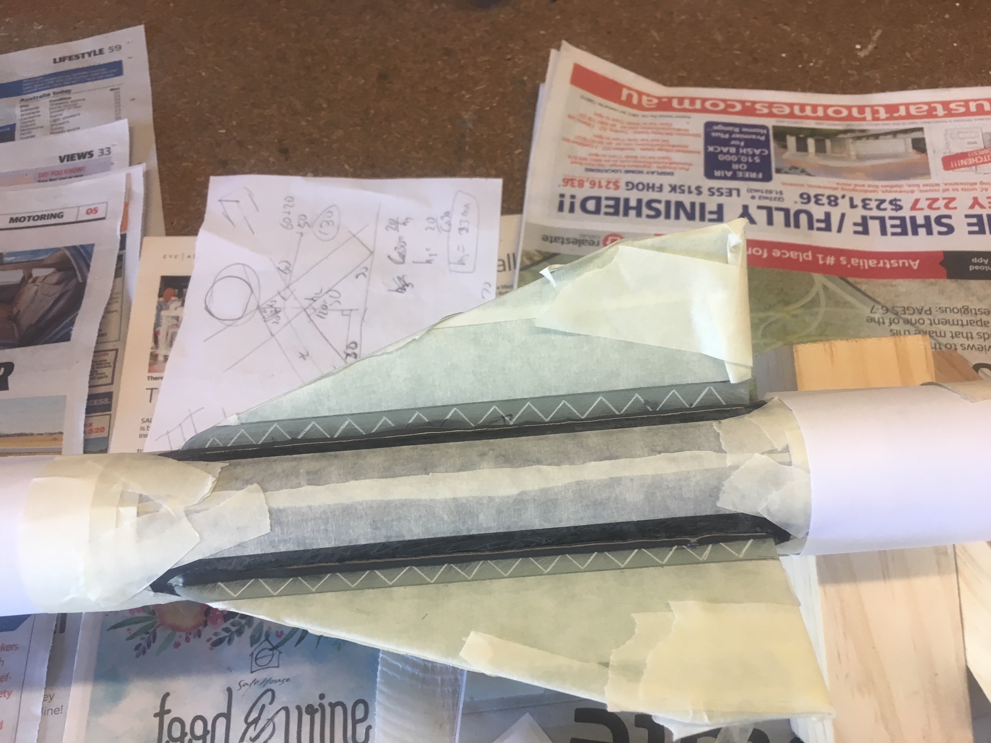
Because the fin fillets are so small, I created ALL the fillets in one go. I actually ran out of epoxy and had to create a small second batch. I have it a few days to cure. Below are some photos of me preparing the rocket for filleting, by taping it up.
Carefully taping up the areas, in preparation for creating fillets.All taped up – ready to apply Epoxy.
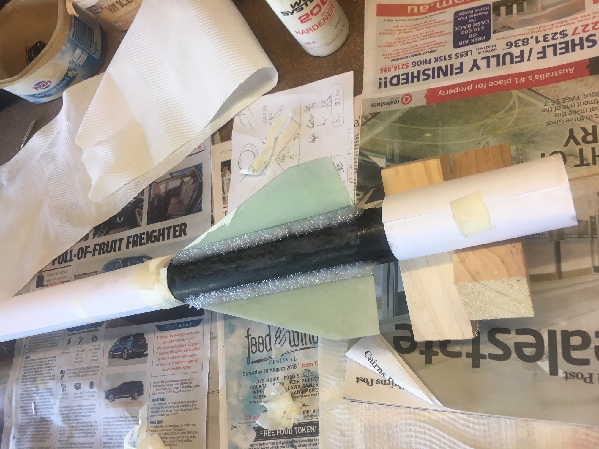
Below are photos of the finished job.
Epoxy fillet created.
Epoxy fillet created – tape removed.
Sanding it down
The finish wasn’t flash, so I decided some sanding was required so that bumps to show through the tip-to-tip. NOTE: The aim was not to sand it down to completely remove the holes; The Tip-to-tip will handle this. I used a AA battery with Grit 60 sand paper.
Taped off areas so that when sanding, I don’t accidentally sand into the wrong areas.
Used Grit 80 to sand down the filletsUsed PCB tube to sand down the fillets. Also used a AA battery for some of the sanding.Started sanding the fillets…Sanding finished! Tape removed.