Winding a 1.8 meter tube

We finally managed to get time to wind a tube. Total length of tube is about 1800mm. Usable length is about 1600mm.

This was the “FIFTH” wind and the most successful to date.

Specs

Layers are

  • 45/-45
  • 30/-30
  • 30/-30
  • 45/-45

I choose this layup structure because analysis suggests it should be able to easily handle L3 rocket design I have in mind.

We used Renlam K3600 Epoxy and we used 50mm heat shrink tape to finish off the wind (squeeze out excess epoxy).

The Wind

The wind took two hours of winding and involved mixing 6 bowls of Epoxy (110ml epoxy in each bowl). about 600 meters of Carbon Fiber was rolled, almost perfectly.


Video of the job

Here is a video of the job. I put some music in the background!


Enjoy!

Removal of the Tube

It hasn’t all been smooth sailing. I’ve only been able to pull it off the mandrel but about 25 cm. This involved using the car, chain, dry-ice and a very stable tree.

Later I put a 12mm bolt through the Carbon Fiber and attached to car via 800kg rated chain. On the other end of the tube (on the Aluminum Mandrel) I attached another bolt and chain around the tree. The Carbon Fiber Tube broke probably about 500kg load (complete guess). The load could not be distributed across the carbon Fiber tube easily and it ripped it with ease.

I had a feeling this would happen, but I felt I had to give it a go.

This bit has been very disappointing; but it has been an incredibly excellent learning exercise.

Filament Winder: The Gears

Gears and where they are used

We utilise XL sized gears for all axis :-

  • The Spindle
  • The Carriage
  • The Filament delivery head

Issues experienced

We had severe issues with the gears/belt that moved the Carriage.  We discovered that it was skipping steps and as a result the carriage would be ahead (or behind) where it should be.

Essentially, we had badly mounted gears at the stepper motor and at the idler end. The mis-alignment wouldn’t normally be a problem, but because of the large length of the Carriage belt, the engineering shortcomings were amplified.

A lot of this was due to my inexperience with gears, some due to badly machined gears. The main problem was mounting these gears on to motors and axles.

We got by in the end.

Carriage Stepper motor

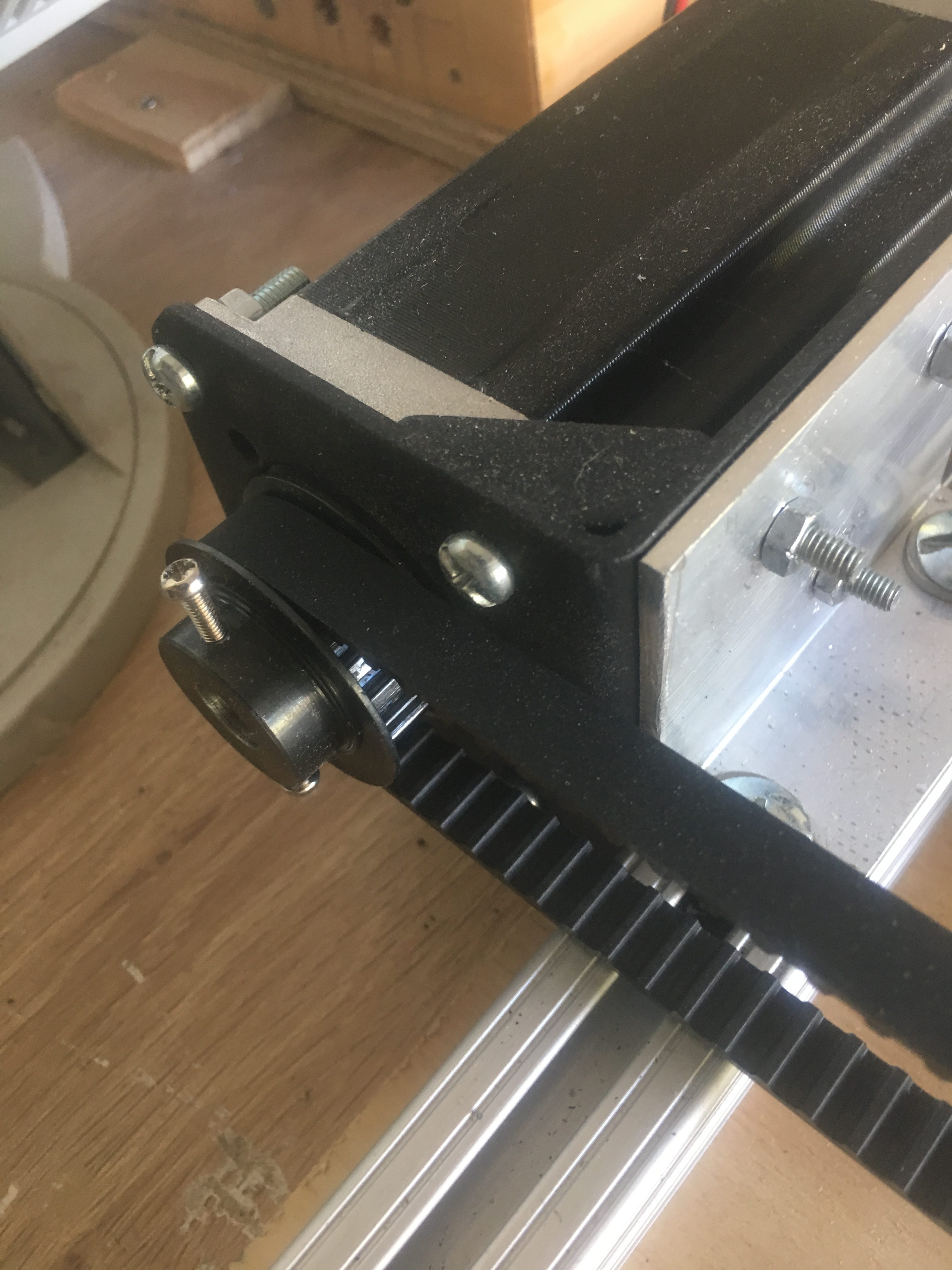
We eventually got a steel XL gear and had a 10mm bore drilled by a local machinist on their lathe. Unfortunately, we should have asked them for a tight fit on to the Stepper Motor and provided them the Stepper Motor. Better still, we should have asked them to cut out a keyed key-way to fit the motor.

We have managed to improve the mount by using tape and careful placement of screws to mount the gear on to the shaft. It isn’t pretty, but it should be functional for now.

Below is a photo of this in use.

Stepper motor and gear that drives the carriage.

Carriage Idler Axle

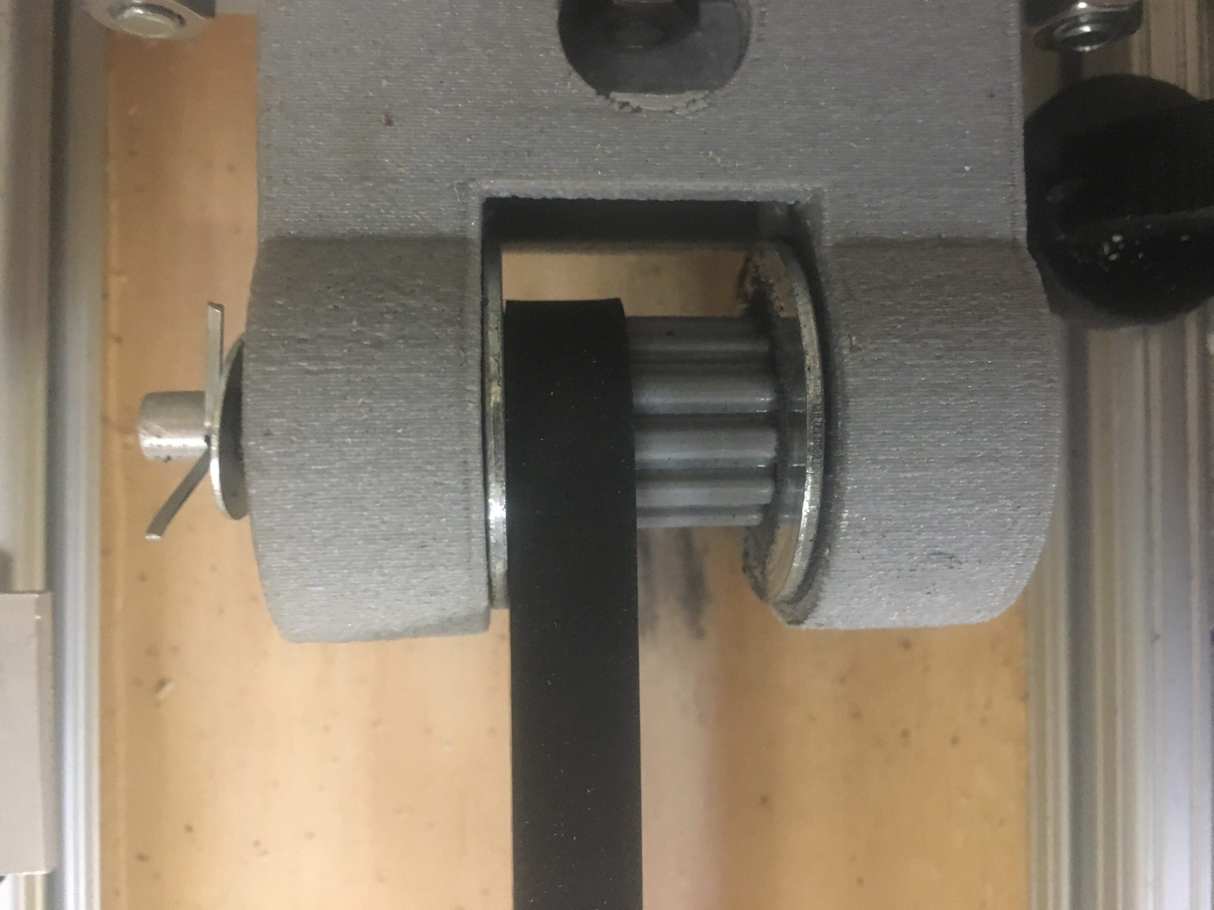
We have at present a 3-D printed gear at the idler end.

The Idler, idler enclosure, belt, bearings all installed.

One of the idler gears we purchased was drilled well, but the gear was not machined correctly. The other idler gear was hand drilled with drill press and the hole isn’t sufficiently centered. The 3-D printed gear is doing very well at present. It has been treated with Acetone vapours and is so smooth/hardened sufficiently to not adversely affect the belt condition; atleast not so far.


Carbon Fiber Delivery head

We printed our own gears for the Carbon Fiber Delivery head. 3-D pics of these are shown below.

WP 3D Thingviewer Lite need Javascript to work.
Please activate and reload the page.

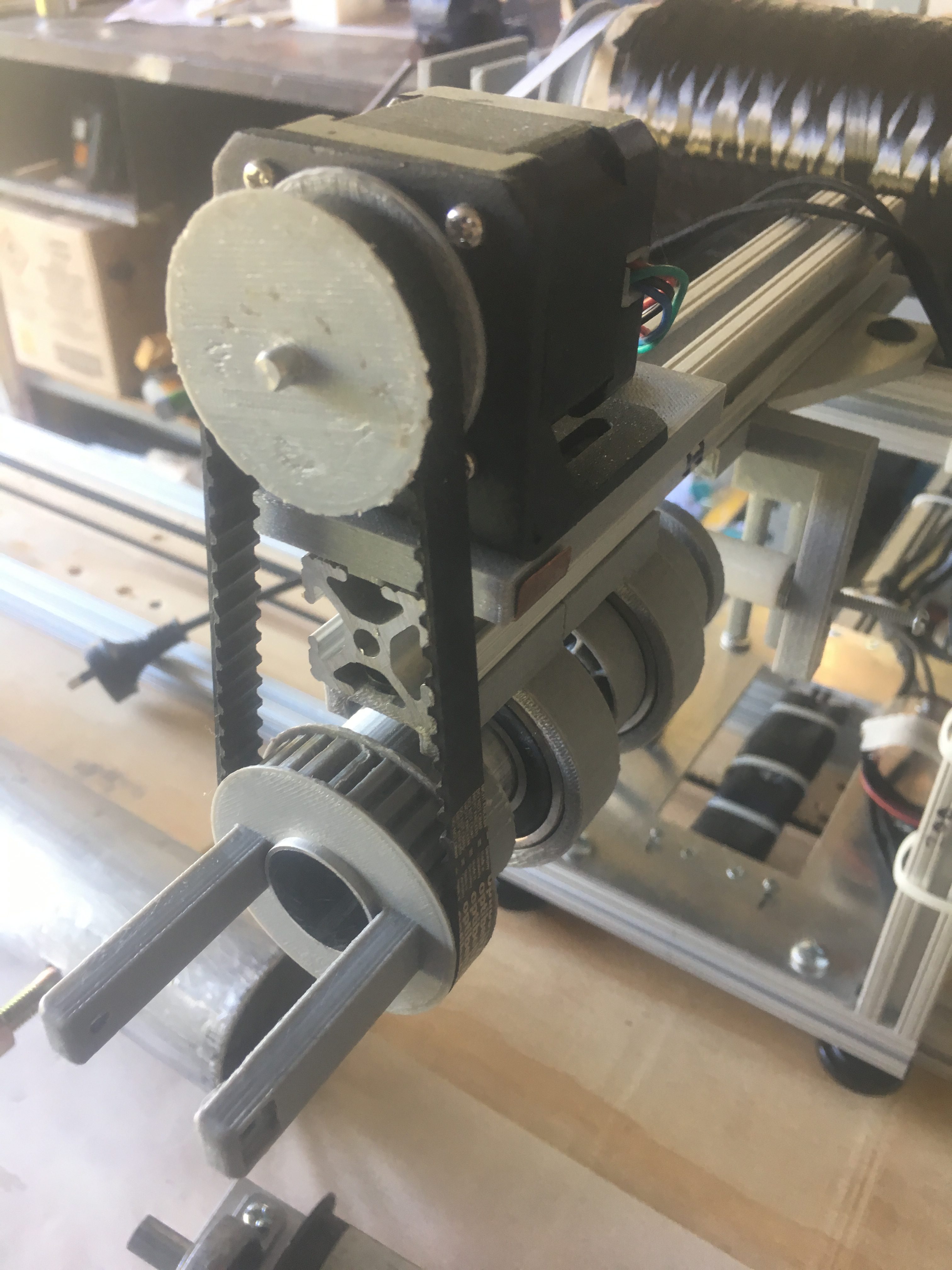
We used these 3-d printed gears because they allowed us to easily come up with design that could be fitted on to the aluminum shaft, which the carbon fiber runs through.

Here is what it looks like in real life.


Z-Axis of winder. This helps to present the carbon fiber at the correct angle.

Spindle Set-up

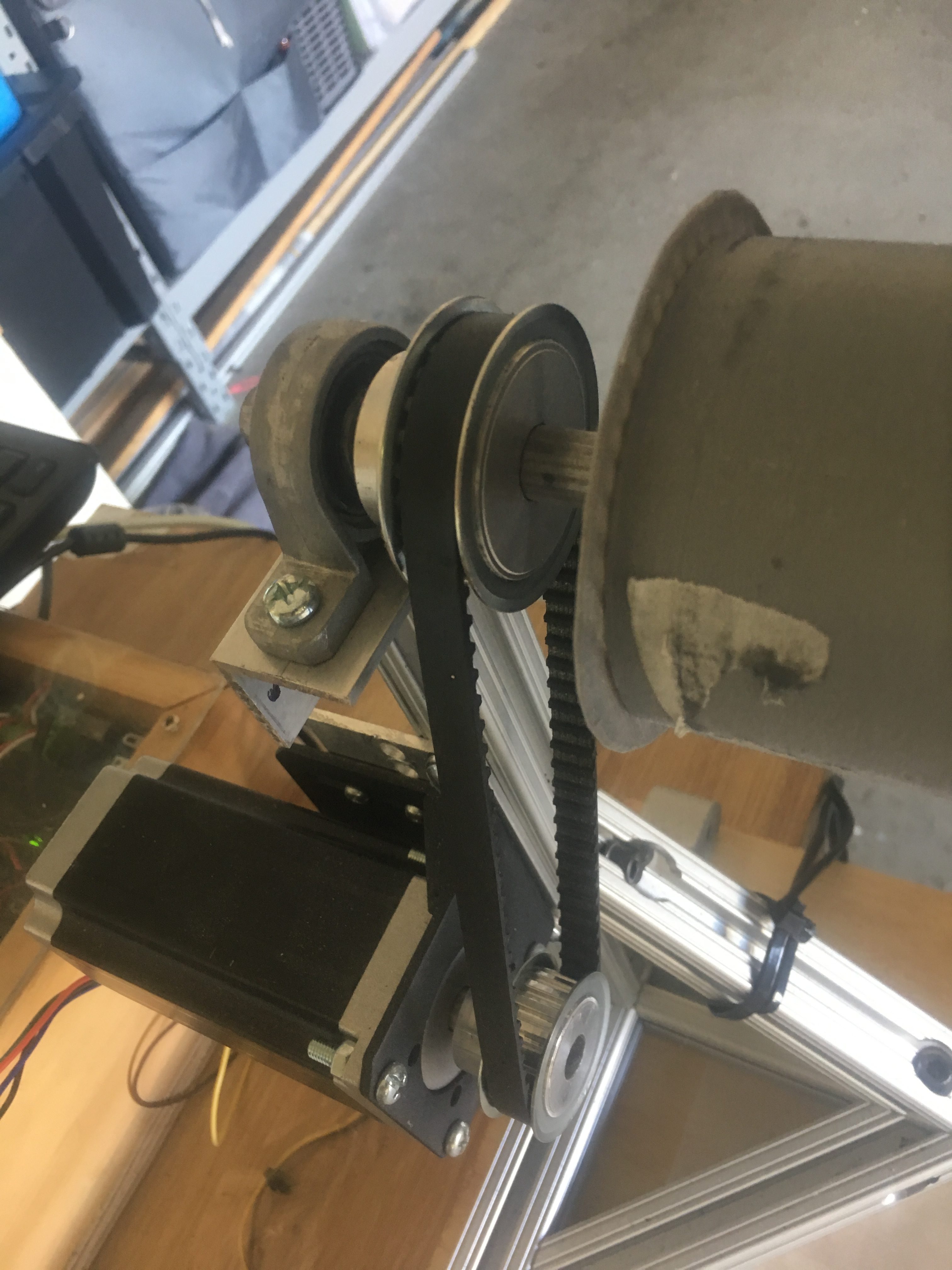
We have 20 teeth gear mounted on the shaft stepper motor and 30 teeth gear mounted on the 12mm shaft that ultimately drives the mandrel. These were drilled using a drill press and so the bores are not perfectly aligned. The alignment is not detrimental to the operation of the spindle.

Below is a screenshot of the set-up


Gears to drive the mandrel


As you will notice, the stepper motor is mounted on to the post. This was not actually by design, but out of necessity because the wrong belt was purchased. This has worked out well nevertheless, by reducing use of  important realestate on the bench.

Filament Winder – The Idler

The carriage is belt driven unit with stepper motor at one end and idler gear at the other end. We discuss the design of the idler in this post.

Overall Design features

The idler gear has evolved considerably, especially since the alignment issues. We use:-

  • Bearing enclosure (3-D print)
  • Two sealed bearing (Metric, 6mm bore)
  • 1/4″ Aluminum axle, sanded at each end to accept the Metric (6mm) bearings
  • 3-D printed gear
  • Two large washers
  • Two smaller washers.

These components are then attached to Aluminum right-angle bracket that is secured to the 1010 bar at the end of the winder.


The Bearing Enclosure

Below is a 3-D view of the Bearings enclosure.

WP 3D Thingviewer Lite need Javascript to work.
Please activate and reload the page.

One can see where the 2 bearings are mounted. This is interference fit. There are three holes which are used to attach this to a aluminum bracket. One can tighten these three bolt/nuts to increase tension in the belt and we can adjust as required to balance the belt.

We have sufficient gap between two bearing compartments for ~22mm gear and several washers to assure there is no belt/ABS plastic abrasion.


The Gear

We purchased several gears, but had problems getting them working – some gears where duds and other gears had holes drilled in them that were not working. In the end, I printed a Gear. A lot of effort went into this gear – mostly trial and error.

Below is what we printed.

idlerGear

We also extended the ABS out a little on each side (the green area) to ensure that any abrasion did NOT occur on the gear teeth. The reasoning is that if we don’t, the teeth will deform from heat and this will help degrade the belt teeth.


After we print it, we treat it with acetone. This hardens and smooths the surface which is EXTREMELY important to preserve belt life.

Everything connected

Below is a photo of all the parts connected and working together.

The Idler, idler enclosure, belt, bearings all installed.


Issues Identified

Destruction of the idler gear

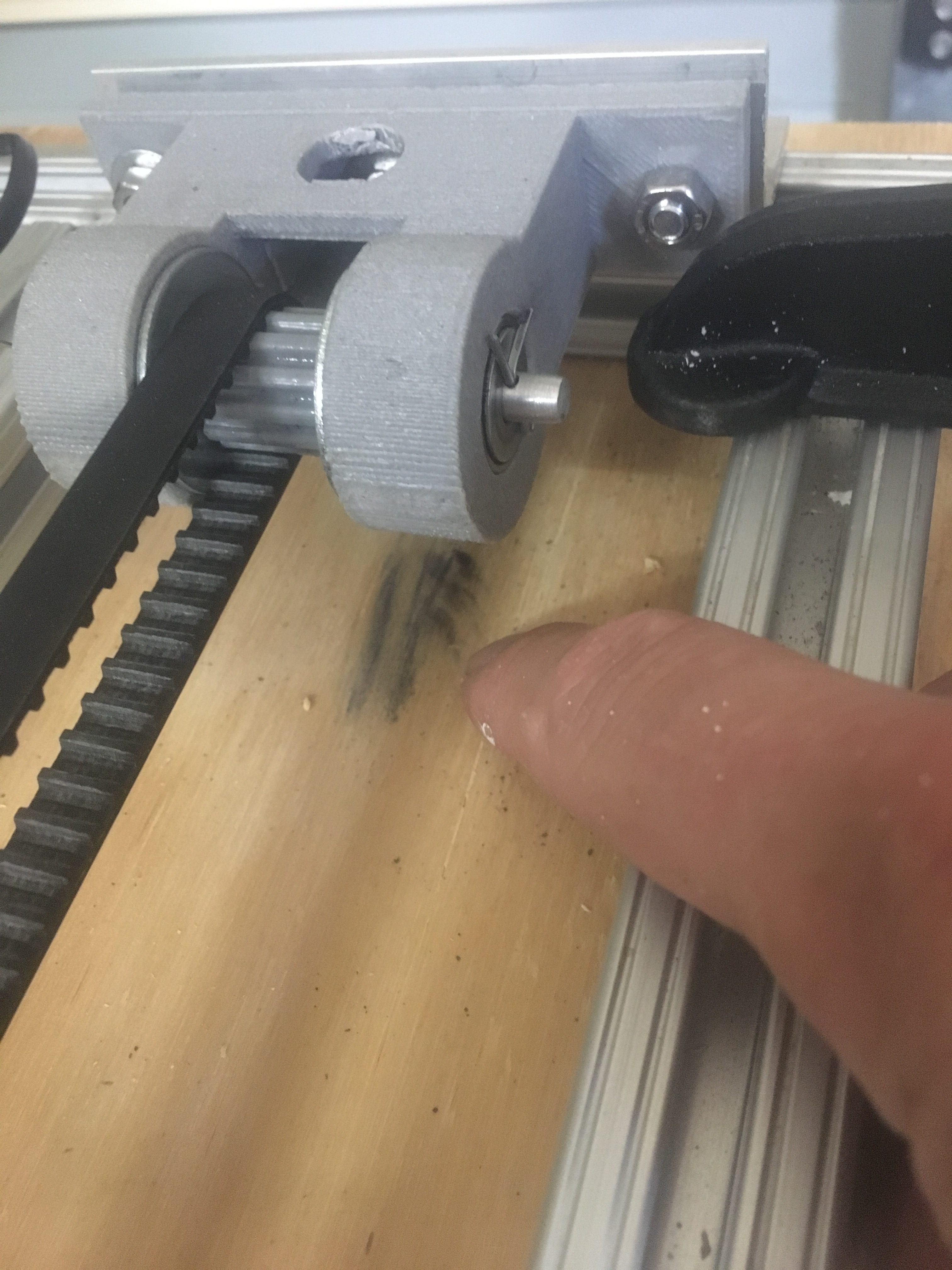
I have noticed that after some use of the winder, a grey powder is being deposited at one end. Please see below.

Notice the powder residue on the wood bench.


At first I thought this might be the belt, but now I suspect it is these “end” pieces that are grinding away. For this reason, I think I’ll need to replace the idler gear occasionally, e.g. every 1 or 2km of filament.


The Belt

The belt ideally would sit in the middle, but it doesn’t. Instead it sits at one end. We can adjust screws to the back of the idler to encourage it to move in one direction, but it eventually goes back to the LEFT position.

I have thought of having fixed guards and this MIGHT be the way to go, however concerns with belt abrasion against the gear have put me off this. For now, we have stainless steel washers to reduce chance of abrasion of belt. So far it has worked well.