Below is a movie showing how I assemble all the components of the payload.
There is still much to do. We intend on installing a camera as well to take a video of the launch from the perspective of a ‘mini’ traveler in the rocket. This is not shown here as we have not yet received the video camera.
We are creating a payload bay that will house the electronics and ultimately all the rest of the hardware. For now, we only require it to take the electronics, which will be all that is needed for the first few flights, to obtain sample data from the Gyroscope. We are leaving enough space so that we can later install stabilisation motors.
This of course is a smaller, cutdown version of the ultimate rocket we wish to launch. However, we want to get a smaller version of this rocket Stabilisation system working on a small one. A proof of concept.
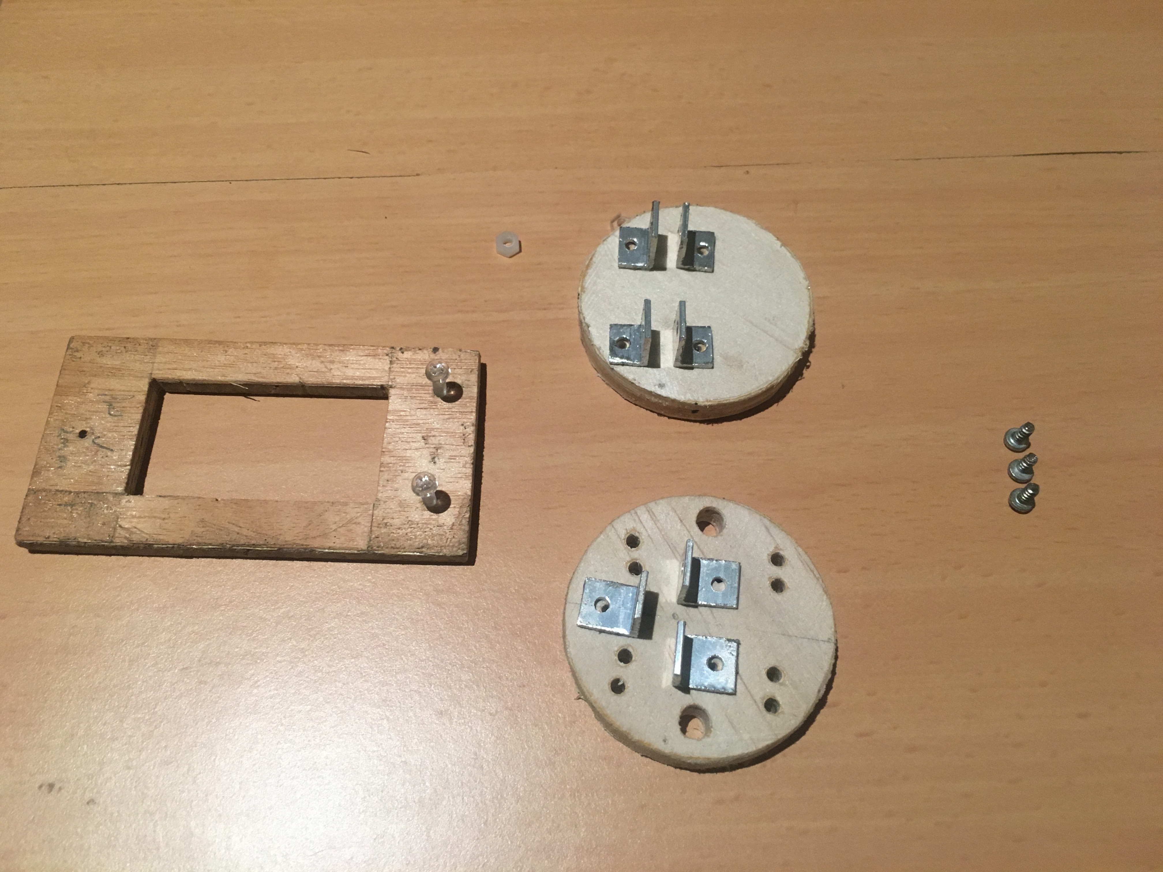
Here are components that make up the electronics bay (just one part of the payload).
Payload tray on left, top payload tray cap above and bottom payload tray cap below.
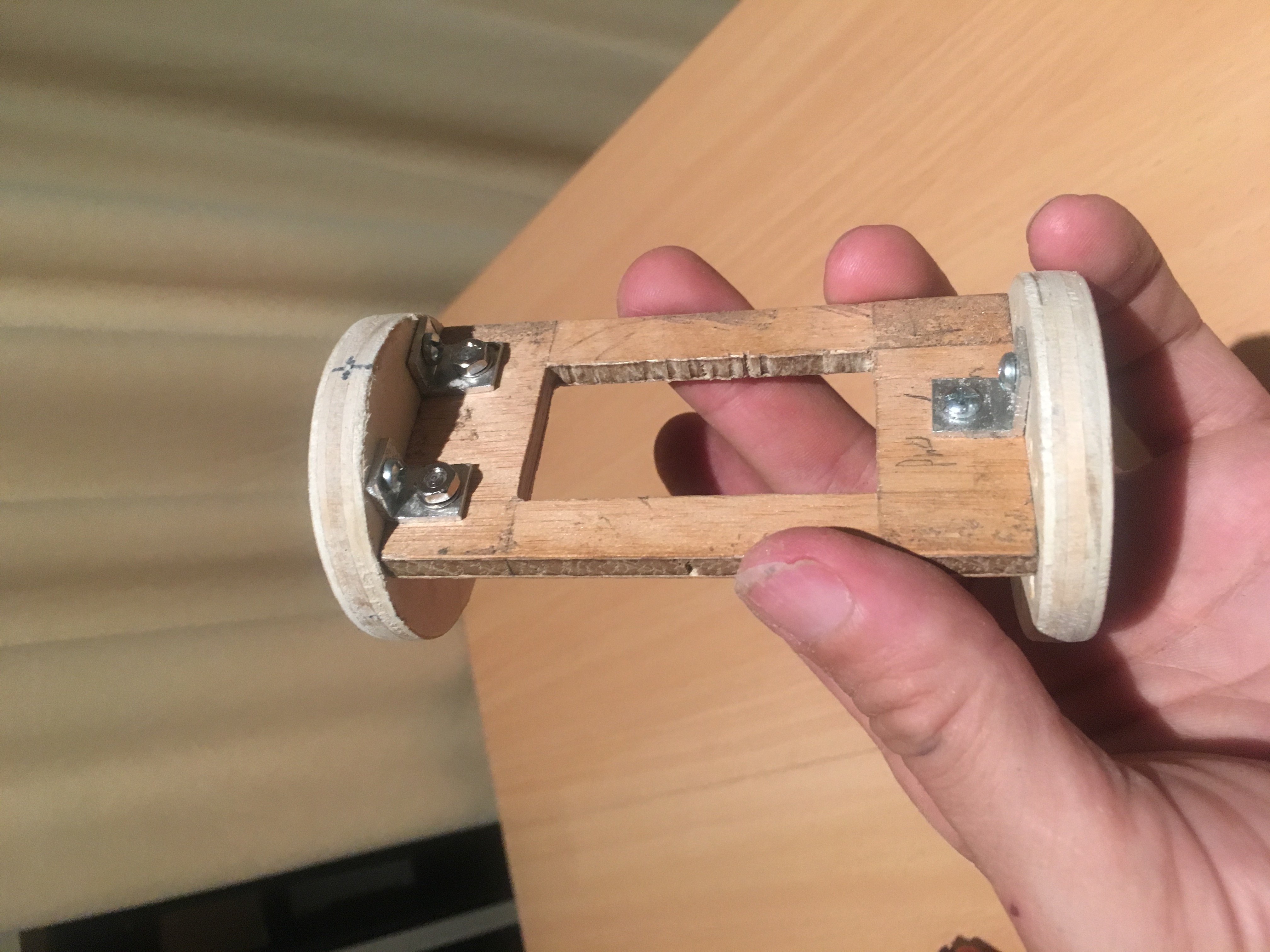
Below are some pictures of the payload bay, partially constructed.
View of partially built payload bay
A rotatary switch will be installed between the top two brackets. Holes will be drilled on either side of the tray, to which we will attach the PCB. Some of the PCB breakout boards will actually sit within the cut-out in the tray. i.e. this cut out is more then just a weight saving measure.
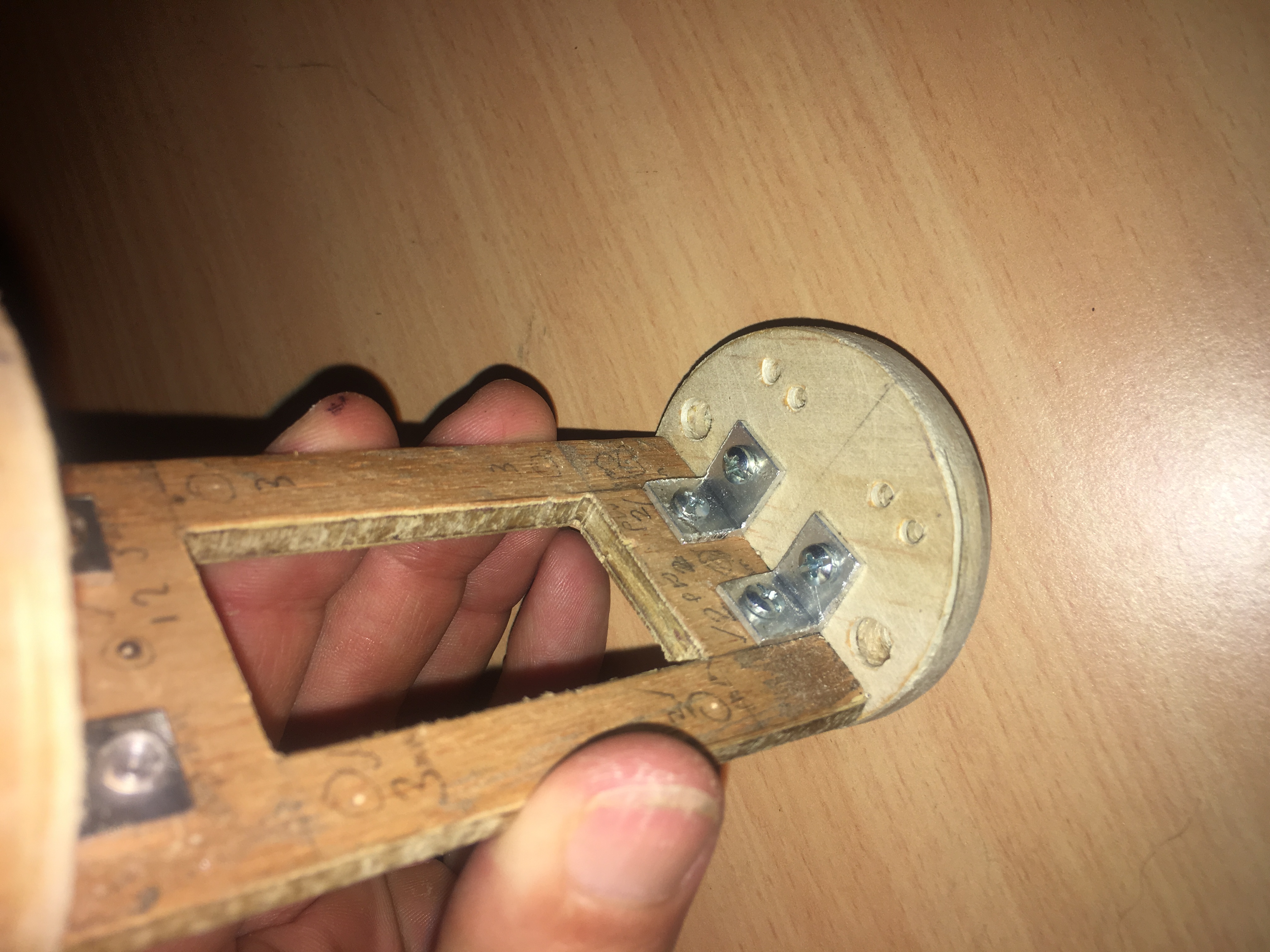
Looking down at bttom plate of payload tray. Notice holes for cable ties, electronic cables and fixing screws.
We hope to get the electronics components later in the week and start building and attaching to the payload tray. We will provide a new Post when this is complete.
A lot of progress has been on the stabilisation system. We have managed to:-
Get the Stepper motors working in 1/4 steps. We needed 1/4 steps because full steps were causing vibrations and we would miss steps.
Use Interrupts and clever coding to calculate (and buffer, using a Ring Buffer) timing values. We didn’t have enough memory to store timings in array and we could calculate just one time interval per step.
Managed to implement Hall Effect sensors to detect when Smoothers are close to pre-determined position. This allows the system to calibrate the smoothers, i.e. move them into an initial starting position.
Managed to get the Gyroscope working error free. We did this by getting to to check the status register to confirm data has been written to the registers. We also implemented a single Wire Read to get all the gyro data, rather then individual reads. This should give us extra cpu cycles while the stepper motors move. Very very critical!
We calculate HIGH/LOW values for X, Y, Z. We also calculate average and variance of these values. We use the high/low values for x, z axis to set the values to Zero, should they fall within the range.
Below is Youtube movie of the system being testing. The video was slowed down because the smoothers move so fast, one cannot pick it up with ones eye!