Managed to add my name to the list of Names going to Mars – 2020 Rover!

Managed to add my name to the list of Names going to Mars – 2020 Rover!
Not long after the launch of March Fly, I decided to commit myself to another large and exciting rocket project. This time, to build an extremely high performance 38mm rocket.
My high level goals for this project are to:-
All rockets that I’ve built to date have been from kits. This will be my first scratch-build rocket. I think I’m up for the challenge.
Below is a screenshot of the rocket from Open Rocket.
In this screenshot, it has the smaller motor in it. Flying this motor would be good as a shake-down test.
Scratch Build doesn’t mean making up the build as a I go along. I am writing up some documentation to help me refine the design and the building steps. This has proved extremely important for the air-frame build already.
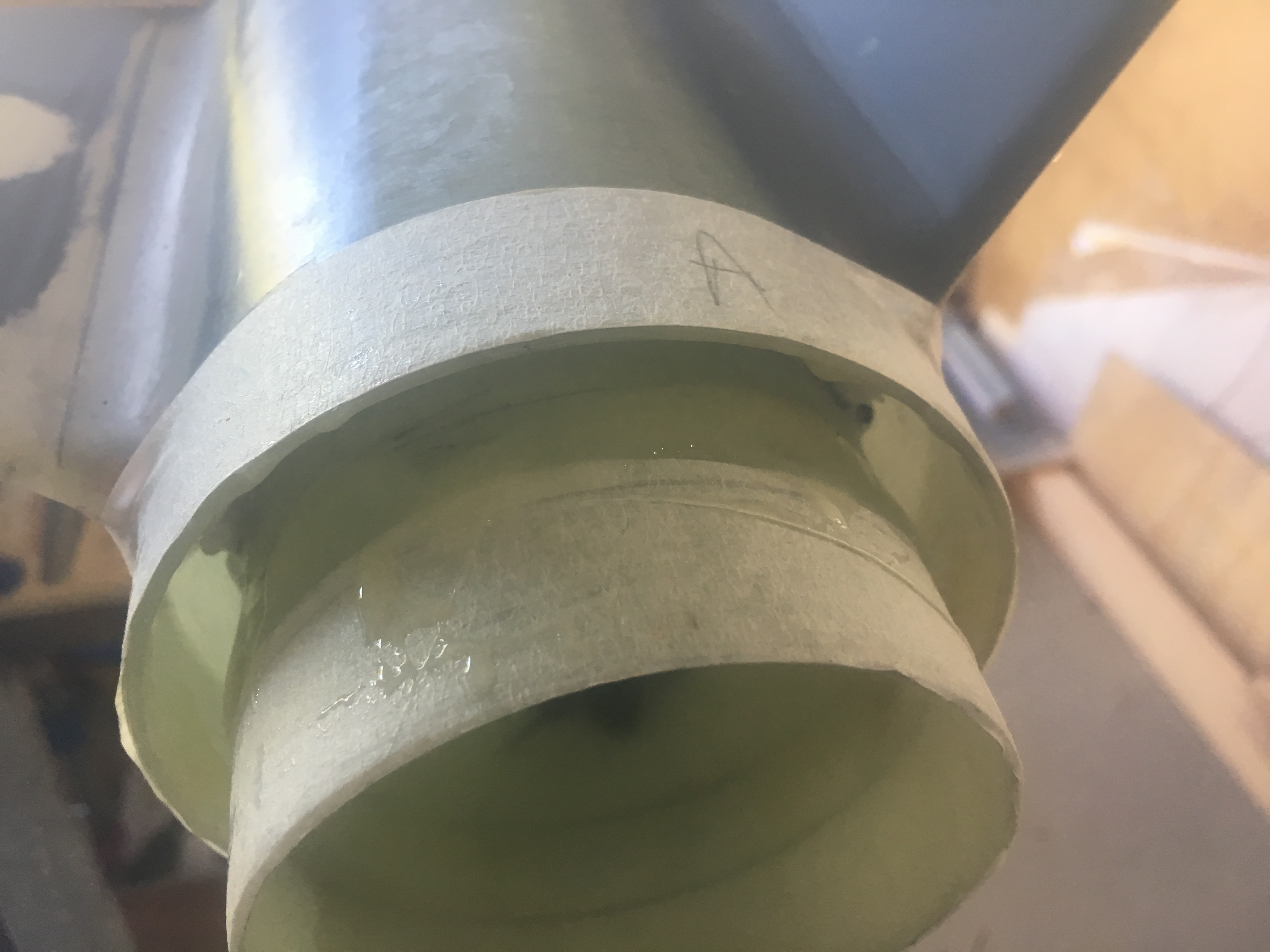
The next step was to glue the centering ring into place.
I decided to use 30min Epoxy glue from AusRocketry. I didn’t want to go for 5 minute and I didn’t want to for 24 hour.
While every effort was made to ensure glue/mess did not make its way on o the surfaces where the Centering Ring is to be glued, some does make its way and so I had to clean it off. There wasn’t much. I used some Methylated spirits to clean the surfaces as well.
Next I wanted to tape up the motor mount exterior, so I would not get any epoxy glue. I also taped up the exterior of the airframe, just to help reduce chance of getting Epoxy on there.
I also decided to stuff some paper up the Motor Mount tube to ensure nothing got up there.
Insert centering ring in ~6mm and mark on the motor mount three places with pencil. This helps us know how far we have to push it in.
This was a carefully thought out job.
Remember, keep rotating the rocket.
Here are some pictures.
Never used the Syringe in the end. Used chopstick instead.
Mixing 24 Epoxy.

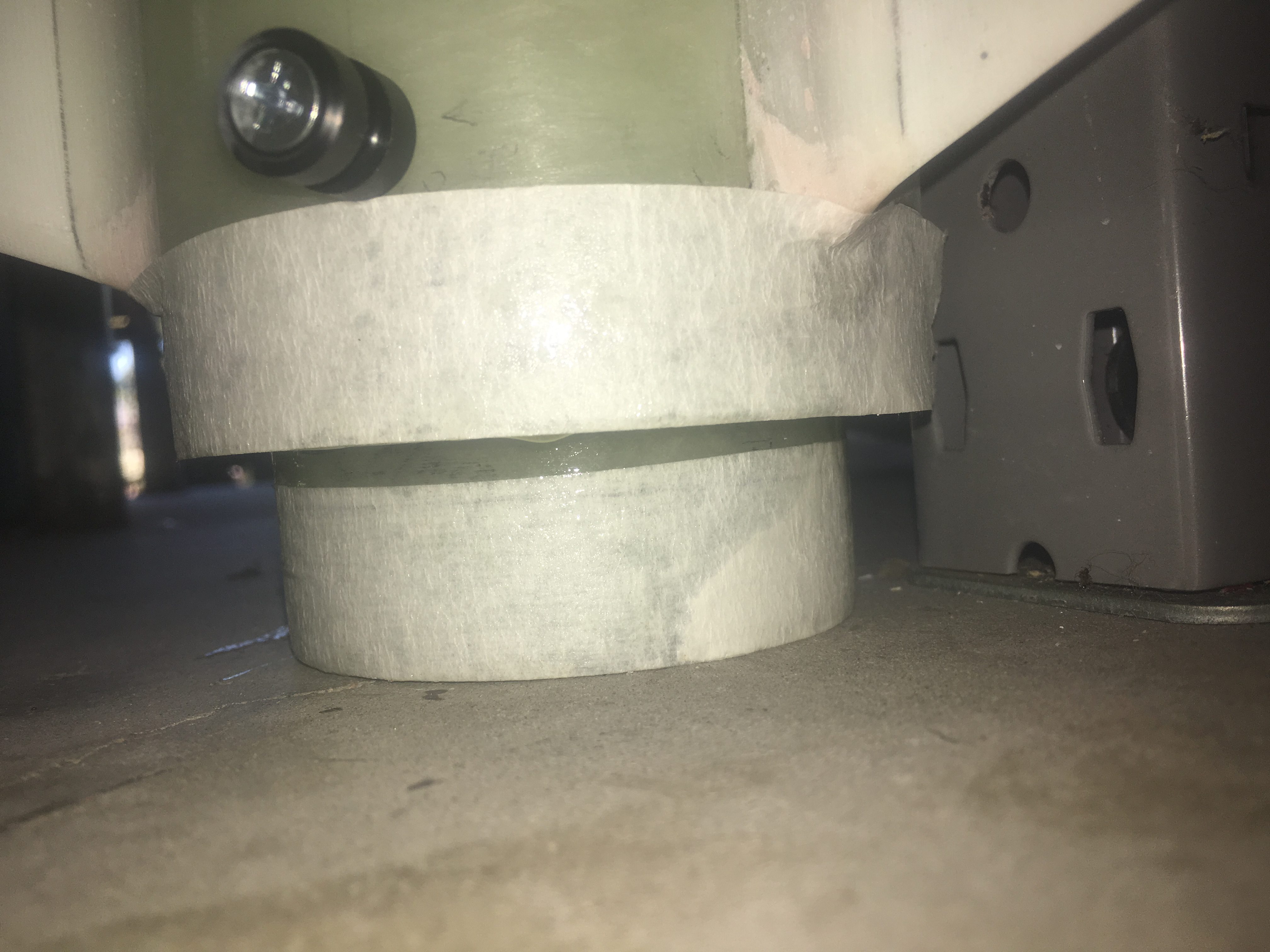
After this I slid the Centering Ring on. This requires two hands, so no photos.
Then I erected the rocket against the workbench, so that Gravity would bring the Epoxy on to the top of the Centering Ring.

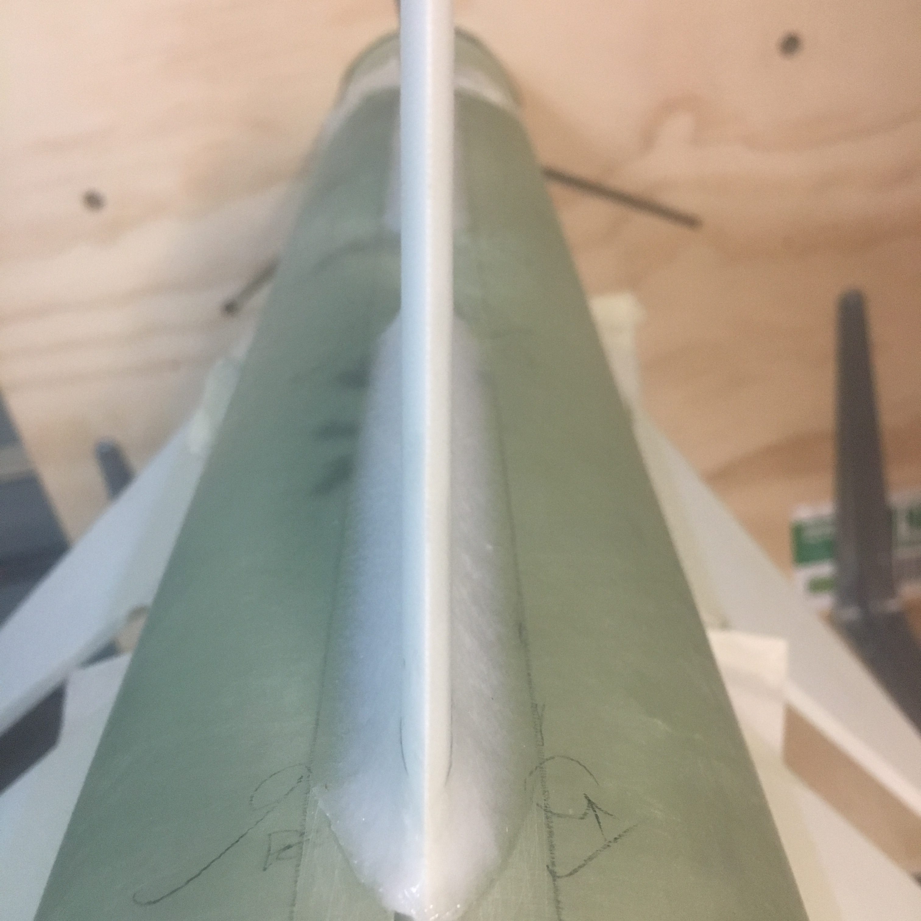
Eventually I applied the final External Fillet Epoxy to the air-frame. They all looked reasonably good, all quite similar in profile and size to the photo below.
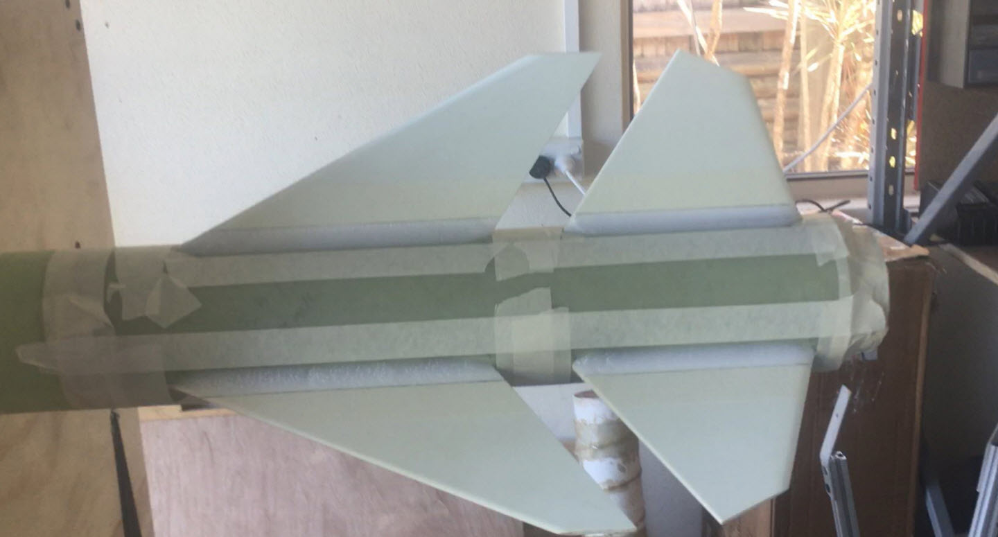
I wanted to avoid sanding the air-frame and fins at all costs. I decided that if I employed masking tape, I’d have to sand through the masking tape before sanding the fins/air-frame and I’d notice in time that I was sanding the wrong thing. Below is a picture of it all taped up.
The next step was to sand them. I had gone to extraordinary lengths to glue Sandpaper to a long stick to sand the fillets. I realised pretty quickly that this was overdo and I did not need along sheet and I did not need a long stick. In-fact, having a long doweling with long strip of sandpaper was counter-productive because the fins, even though they were VERY well aligned, the slight differences in epoxy between Fore/Aft fins meant that the sand paper would not reach all along the whole length of the fillet. The other fin was “in the way”.
So I pretty quickly went for a smaller doweling with about 10 cm of Sand paper just wrapped around it with some masking tape to hold it in place at one end. This allowed me to sand each fillet individually. No glue, it was so much easier.
I used the following sandpaper in the order shown:-
I used water for Grit 600 and Grit 1200. i.e. Wet and Dry.
I had to be very careful to keep the doweling parallel to surfaces, to ensure I produced a curved profile along the whole length of the external fillet.
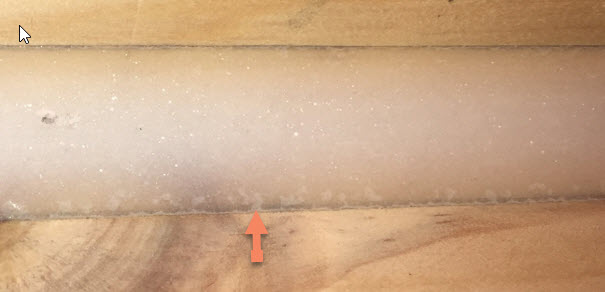
The results were good, but not as impressive as I had hoped. Near the edges of the fillet there were craters. I couldn’t risk sanding into the air-frame, so I had to think about how to deal with them.
I didn’t keep a photo of the cratering, so I’ve retrieved a photo of cratering in some of early practice fillets.
I’ll leave the solution to this in the next Post.
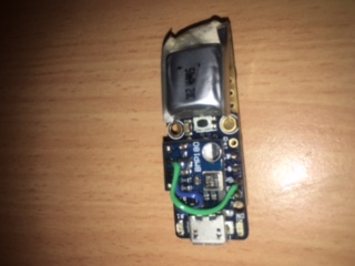
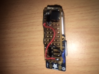
I put together a small air-pressure sensor that could fit inside a Junior Model rocket nose cone. The components used were:-
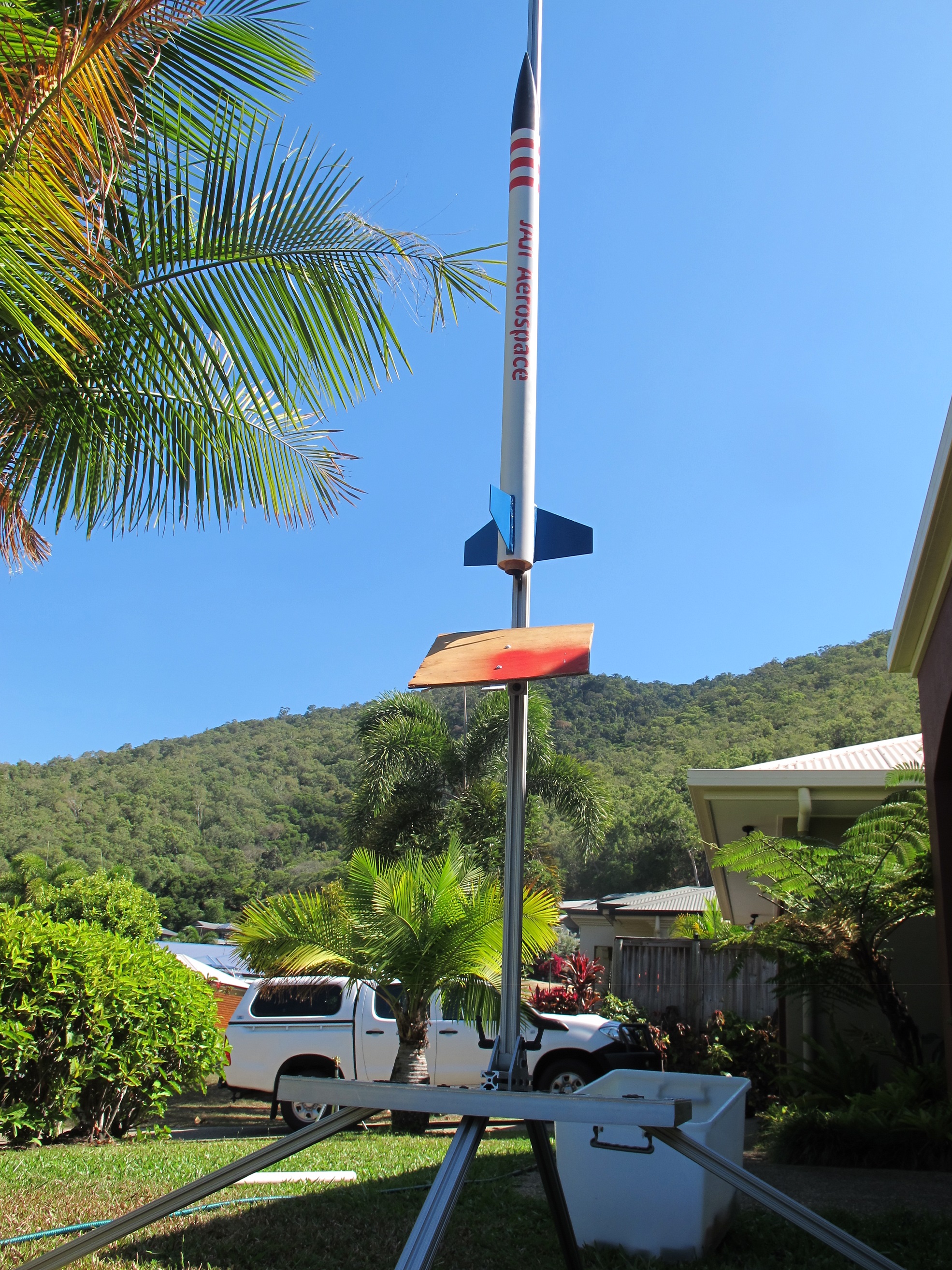
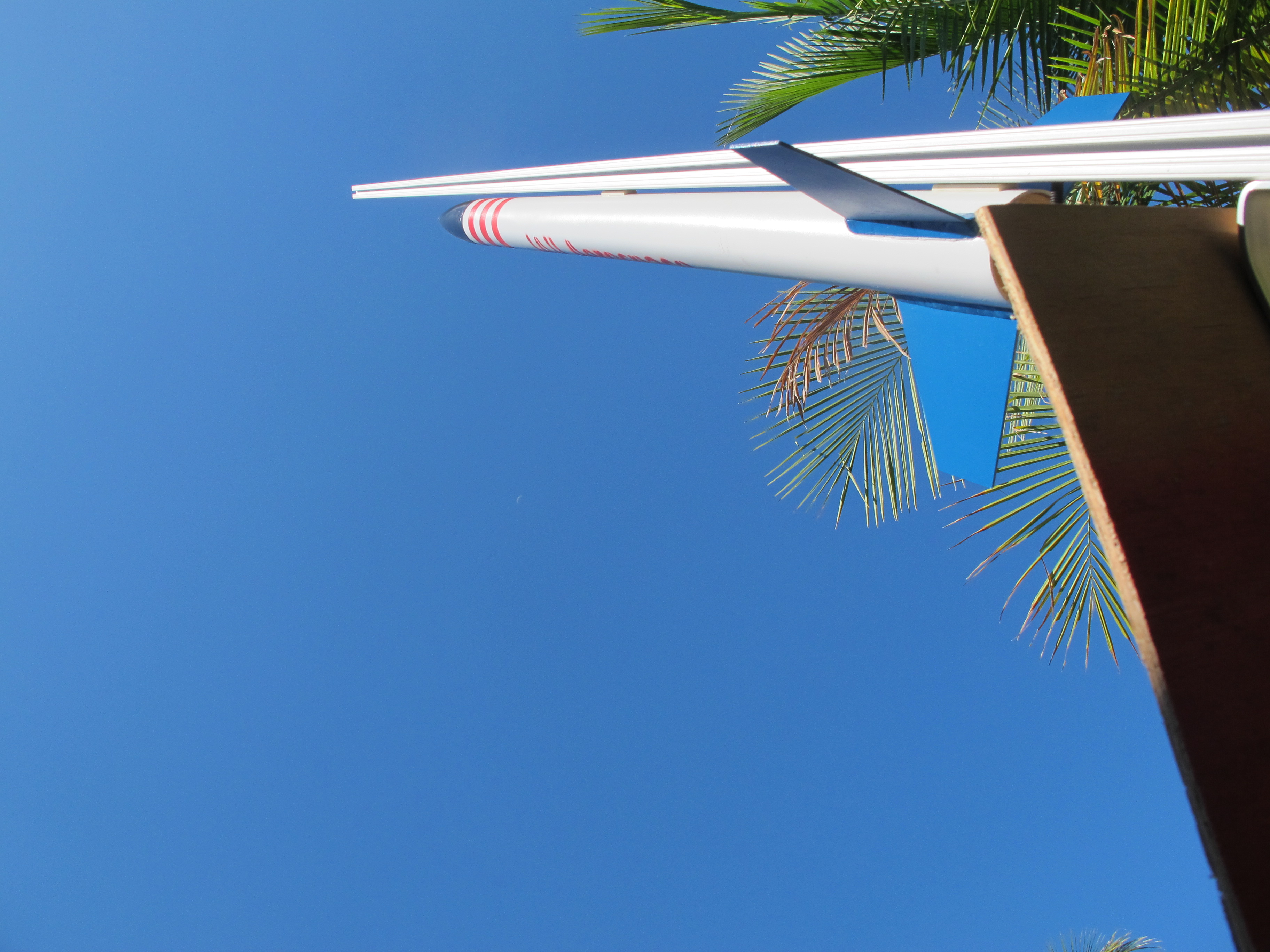
Some pictures of this are shown below.
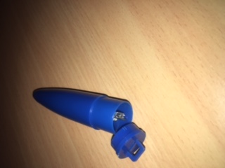
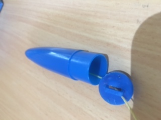
NOTE: We had a very small hole drilled into the side of the Nose Cone to allow air pressure to equalise.
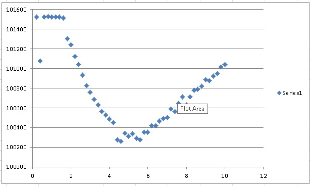
The code had to be able to detect a reduction in Air Pressure, to sense that the rocket flight had started. Then it had to record the last 10 measurements plus another 40 measurements inside the EPROM of the Arduino. We had a measurement taking place every 0.2 seconds, so we got 10 seconds of measurements.
And it worked quite well! Below is a plot of points for maiden flight.
Below is the code I used. Please note, that I have not included a cut-down version of SoftwareSerial. Essentially the Trinket never needs to receive data on its software Serial link, so I commented out code in the library. This allows the program to JUST fit inside the 5310 Bytes.
#include <TinyWireM.h>
#include <SoftwareSerial.h>
#include <EEPROM.h>

// Uncomment following line, recompile and upload to
// read results. This is because we don't have enough
// space to have READ and WRITE functionality co-existing.
// #define READ

SoftwareSerial mySerial(4, 3); // RX, TX

int addr = 0; // EEPROM memory

#define BMP180_ADDRESS 0x77 // I2C address of BMP180
// define calibration data for temperature:
int ac1;
int ac2;
int ac3;
unsigned int ac4;
unsigned int ac5;
unsigned int ac6;
int b1;
int b2;
int mb;
int mc;
int md;
long b5;
//define variables for pressure and temperature calculation
long x1,x2;
//define variables for pressure calculation
long x3,b3,b6,p;
unsigned long b4,b7;
//define variables for temperature and pressure reading

long p_avg = 0;
byte iter = 0;
int p_threshold = 200;
int p_threshold_count_required = 3;
int p_threshold_count = 0;
boolean launch_detected = false;
boolean information_saved = false;
long rawpressure;


long hist_measurements[10];
long measurements[40];
short hist_measurement_index = 0;
short measurement_index = 0;


const unsigned char OSS = 3; // Oversampling Setting
/* blz 12 Datasheet
OSS=0 ultra Low Power Setting, 1 sample, 4.5 ms 3uA
OSS=1 Standard Power Setting, 2 samples, 7.5 ms 5uA
OSS=2 High Resolution, 4 samples, 13.5 ms 7uA
OSS=3 Ultra High Resolution, 2 samples, 25.5 ms 12uA
*/


void setup() {

 pinMode(1, OUTPUT);
 digitalWrite(1, HIGH);


 TinyWireM.begin();
 delay(5000);

 // First read calibration data from EEPROM
 ac1 = bmp180ReadInt(0xAA);
 ac2 = bmp180ReadInt(0xAC);
 ac3 = bmp180ReadInt(0xAE);
 ac4 = bmp180ReadInt(0xB0);
 ac5 = bmp180ReadInt(0xB2);
 ac6 = bmp180ReadInt(0xB4);
 b1 = bmp180ReadInt(0xB6);
 b2 = bmp180ReadInt(0xB8);
 mb = bmp180ReadInt(0xBA);
 mc = bmp180ReadInt(0xBC);
 md = bmp180ReadInt(0xBE);


 delay(5000);
 mySerial.begin(9600);
 // mySerial.println("S");
 digitalWrite(1, LOW);

#ifdef READ
 // uncomment this and comment out the writeResults below when wanting to read values.
 readResults();
#endif

}

void loop() {
 // first, read uncompensated temperature
 //temperature = bmp180ReadUT();
 //and then calculate calibrated temperature
 unsigned int rawtemp = bmp180ReadUT();
 b5 = computeB5 (rawtemp);
 // temperature = bmp180CorrectTemperature(bmp180ReadUT());
 // then , read uncompensated pressure
 rawpressure = bmp180ReadUP();

 b6 = b5 - 4000;
 // Calculate B3
 x1 = (b2 * (b6 * b6)>>12)>>11;
 x2 = (ac2 * b6)>>11;
 x3 = x1 + x2;
 b3 = (((((long)ac1)*4 + x3)<<OSS) + 2)>>2;

 // Calculate B4
 x1 = (ac3 * b6)>>13;
 x2 = (b1 * ((b6 * b6)>>12))>>16;
 x3 = ((x1 + x2) + 2)>>2;
 b4 = (ac4 * (unsigned long)(x3 + 32768))>>15;

 b7 = ((unsigned long)(rawpressure - b3) * (50000>>OSS));
 if (b7 < 0x80000000) {
 p = (b7<<1)/b4;
 } else {
 p = (b7/b4)<<1;
 }
 x1 = (p>>8) * (p>>8);
 x1 = (x1 * 3038)>>16;
 x2 = (-7357 * p)>>16;
 p += (x1 + x2 + 3791)>>4;


// Debugging
// mySerial.println(p);

 if (iter < 10) {
 p_avg = (iter * p_avg + p)/(iter+1);
 iter++;


// Debugging
/*
 if (iter == 10) {
 mySerial.print("a");
 mySerial.println(p_avg);

 mySerial.println(((p_avg >> 32) & 0xff), HEX);
 mySerial.println(((p_avg >> 16) & 0xff), HEX);
 mySerial.println(((p_avg >> 8) & 0xff), HEX);
 mySerial.println((p_avg & 0xff), HEX);

 delay(120);
 }
*/

 }

 if ( p_avg - p > p_threshold) {
 p_threshold_count++;
 } else {
 p_threshold_count = 0;
 }

 if (p_threshold_count >= p_threshold_count_required) {
 launch_detected = true;
 }


#ifndef READ
 if (launch_detected) {
 digitalWrite(1, HIGH);
 measurements[measurement_index] = p;
 measurement_index++;
 if (measurement_index > 40) {
 measurement_index = 0;
 if (! information_saved) {
 information_saved = true;
 writeResults (p_avg, hist_measurement_index);
 }
 }

 } else {
 hist_measurements[hist_measurement_index] = p;
 hist_measurement_index++;
 if (hist_measurement_index > 9) hist_measurement_index = 0;
 }
#endif

 // mySerial.println(rawtemp);
 // mySerial.println(temperature);
 // mySerial.println(b5);
 delay(200);
}


int bmp180ReadInt(unsigned char address)
{
 unsigned char msb, lsb;
 TinyWireM.beginTransmission(BMP180_ADDRESS);
 TinyWireM.send(address);
 TinyWireM.endTransmission();
 TinyWireM.requestFrom(BMP180_ADDRESS, 2);
 while(TinyWireM.available()<2);
 msb = TinyWireM.receive();
 lsb = TinyWireM.receive();
 return (int) msb<<8 | lsb;
}

unsigned int bmp180ReadUT()
{
 unsigned int ut;

 // Write 0x2E into Register 0xF4 and wait at least 4.5mS
 // This requests a temperature reading
 // with results in 0xF6 and 0xF7
 TinyWireM.beginTransmission(BMP180_ADDRESS);
 TinyWireM.send(0xF4);
 TinyWireM.send(0x2E);
 TinyWireM.endTransmission();

 // Wait at least 4.5ms
 delay(10);

 // Then read two bytes from registers 0xF6 (MSB) and 0xF7 (LSB)
 // and combine as unsigned integer
 ut = bmp180ReadInt(0xF6);
 return ut;
}

/*
double bmp180CorrectTemperature(unsigned int ut)
{
 x1 = (((long)ut - (long)ac6)*(long)ac5) >> 15;
 x2 = ((long)mc << 11)/(x1 + md);
 b5 = x1 + x2;
 return (((b5 + 8)>>4));
}
*/


// Read the uncompensated pressure value
unsigned long bmp180ReadUP()
{
 unsigned char msb, lsb, xlsb;
 unsigned long up = 0;

 // Write 0x34+(OSS<<6) into register 0xF4
 // Request a pressure reading w/ oversampling setting
 TinyWireM.beginTransmission(BMP180_ADDRESS);
 TinyWireM.send(0xF4);
 TinyWireM.send(0x34 + (OSS<<6));
 TinyWireM.endTransmission();

 // Wait for conversion, delay time dependent on OSS
 // delay(5 + (5*OSS));
 delay(26);

 // Read register 0xF6 (MSB), 0xF7 (LSB), and 0xF8 (XLSB)
 TinyWireM.beginTransmission(BMP180_ADDRESS);
 TinyWireM.send(0xF6);
 TinyWireM.endTransmission();
 TinyWireM.requestFrom(BMP180_ADDRESS, 3);

 // Wait for data to become available
 while(TinyWireM.available() < 3)
 ;
 msb = TinyWireM.receive();
 lsb = TinyWireM.receive();
 xlsb = TinyWireM.receive();

 up = (((unsigned long) msb << 16) | ((unsigned long) lsb << 8) | (unsigned long) xlsb) >> (8-OSS);

 return up;
}


double bmp180CorrectPressure(unsigned long up)
{
 b6 = b5 - 4000;
 // Calculate B3
 x1 = (b2 * (b6 * b6)>>12)>>11;
 x2 = (ac2 * b6)>>11;
 x3 = x1 + x2;
 b3 = (((((long)ac1)*4 + x3)<<OSS) + 2)>>2;

 // Calculate B4
 x1 = (ac3 * b6)>>13;
 x2 = (b1 * ((b6 * b6)>>12))>>16;
 x3 = ((x1 + x2) + 2)>>2;
 b4 = (ac4 * (unsigned long)(x3 + 32768))>>15;

 b7 = ((unsigned long)(up - b3) * (50000>>OSS));
 if (b7 < 0x80000000) {
 p = (b7<<1)/b4;
 } else {
 p = (b7/b4)<<1;
 }
 x1 = (p>>8) * (p>>8);
 x1 = (x1 * 3038)>>16;
 x2 = (-7357 * p)>>16;
 p += (x1 + x2 + 3791)>>4;

 return p;
}


int32_t computeB5(int32_t UT) {
 int32_t X1 = (UT - (int32_t)ac6) * ((int32_t)ac5) >> 15;
 int32_t X2 = ((int32_t)mc << 11) / (X1+(int32_t)md);
 return X1 + X2;
}


// avg_pressure = 32-bit measurement of air pressure - AVERAGE
// hist_index = where we are up to in the histortical measurements...the place of the last value
// This helps us know where the start/end numbers are in the historical data...when we go to
// put all the data back together again.
// historical_measurements = pointer to where the historical measurements are
// measurements = pointer to post launch test results are stored.
void writeResults(long avg_pressure, short hist_index)
{
 // Save the Average value
 EEPROM.write(addr, ((avg_pressure >> 16) & 0xff));
 addr++;
 EEPROM.write(addr, ((avg_pressure >> 8) & 0xff));
 addr++;
 EEPROM.write(addr, (avg_pressure & 0xff));
 addr++;

 EEPROM.write(addr, hist_index);
 addr++;
 for (int i = 0; i < 10; i++) {
 EEPROM.write(addr, ((hist_measurements[i] >> 16) & 0xff));
 addr++;
 EEPROM.write(addr, ((hist_measurements[i] >> 8) & 0xff));
 addr++;
 EEPROM.write(addr, (hist_measurements[i] & 0xff));
 addr++;
 }

 for (int i = 0; i < 40; i++) {
 EEPROM.write(addr, ((measurements[i] >> 16) & 0xff));
 addr++;
 EEPROM.write(addr, ((measurements[i] >> 8) & 0xff));
 addr++;
 EEPROM.write(addr, (measurements[i] & 0xff));
 addr++;
 }

 int i = 0;
 while (i < 100) {
 digitalWrite(1, HIGH);
 delay(50);
 digitalWrite(1, LOW);
 delay(150);
 i++;
 }
}


void readResults()
{
 byte val;
 for (int i = 0; i < 154; i++) {
 val = EEPROM.read(i);
 mySerial.println(val, HEX);
 }

 while(1);
}
Then I needed to write a PERL script to interrogate these data from the Serial Port and put in a CSV File.
#!/usr/bin/perl

$pressure_file = "data.txt";
my $data_index = 1;

open(my $fh, "<", $pressure_file)
 or die "cannot open < " . $pressure_file . ": $!";

my $line_number = 1;
while ($line = <$fh>)
{
 #print "Processing: " . $line;
 if ($line_number <= 3 ){
 $val = hex($line);
 $avg = $avg + 256**(3 - $line_number) * $val;
# print "Line: " . $line;
# print "Line Number: " . $line_number . "\n";
# print "AVG: " . $avg . "\n";
 }

 if ($line_number == 3) {
 print "Avg Pressure: " . $avg . "\n";
 }

 # Find Starting point in historical data
 if ($line_number == 4) {
 $start_point = $line + 1;
 if ($start_point == 11) {
 $start_point = 1;
 }
 print "Starting Point: " . $start_point . "\n";
 }

 if ($line_number > 4) {
 $v_data_idx_mod = ($line_number - 5) % 3;
# print "MOD: " . $v_data_idx_mod . "\n";
 $val = hex($line);
 $v_data = $v_data + 256 ** (2 - $v_data_idx_mod) * $val;
# print $val . " - " . $v_data_idx_mod . "\n";

 if ($v_data_idx_mod == 2) {
 # print "Reading: " . $v_data . "\n";
 if ($data_index <= 10) {
 $historical_data[$data_index] = $v_data;
 } else {
 $measurement_index = $data_index - 10;
 $measurement[$measurement_index] = $v_data;
 }
# print $v_data . "\n";
 $v_data = "";
 $data_index++;
 }


 }

 $line_number++;
}

close $fh;


$historical_index = $start_point;
print "STARTING POINT: $historical_index \n";
$i = 1;

while ($i <= 10) {
$v_final[$i] = $historical_data[$historical_index];

$historical_index = $historical_index + 1;
if ($historical_index > 10) {
 $historical_index = 1;
}
$i++;
}

$i = 1;
$measurement_index = 11;
while ($i <= 40) {
$v_final[$measurement_index] = $measurement[$i];

$measurement_index++;
$i++;
}


# Cycle through data and print it out
$i = 1;
while ($i <= 50) {
$time = 0.2 * $i;
print "$time," . $v_final[$i] . "\n";
$i++;
}
It all seems quite desperate, but this is what you need to do if you want to make it small and fit inside the Nose Cone!
The total weight of this unit was 5 grams.
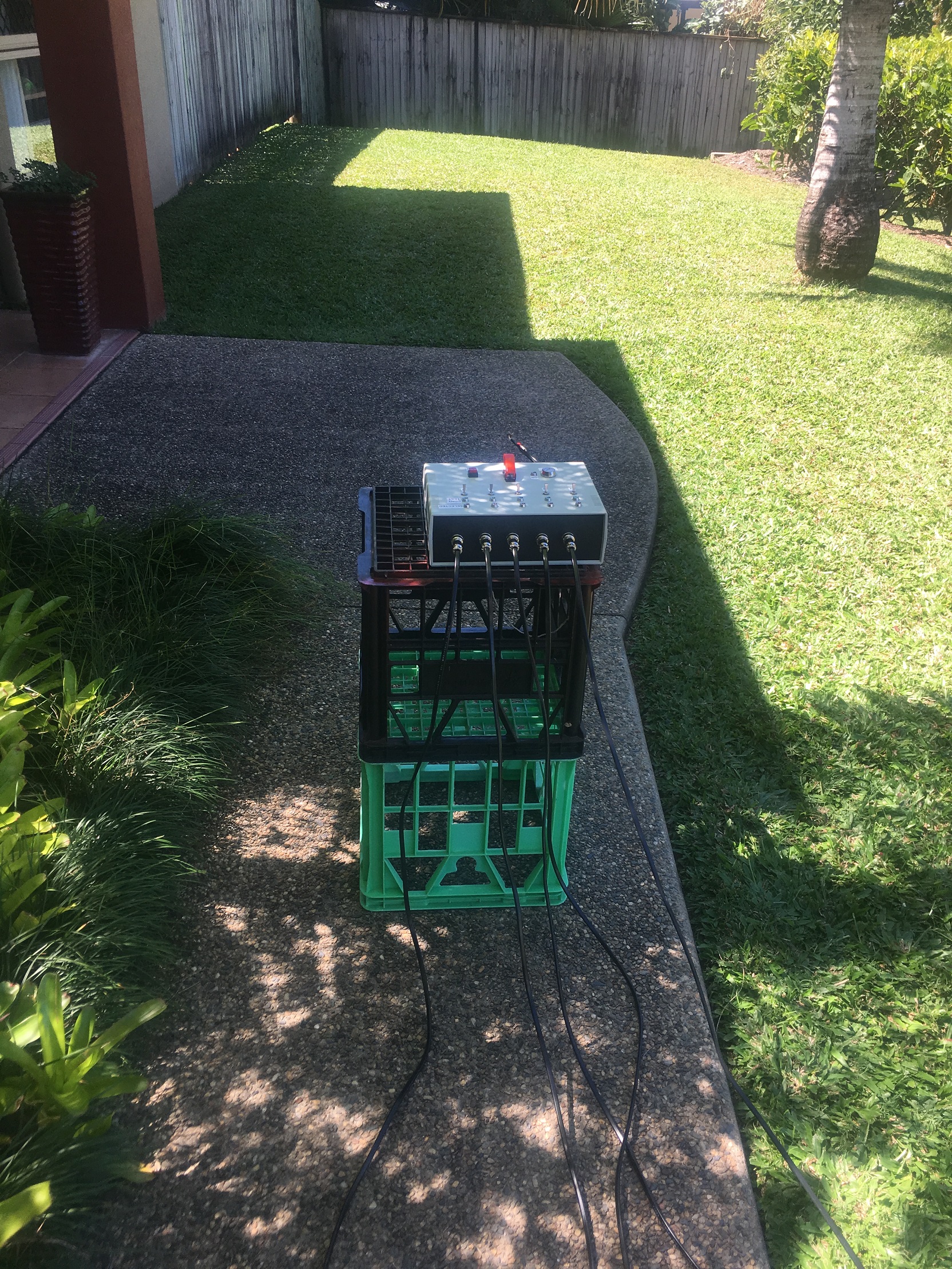
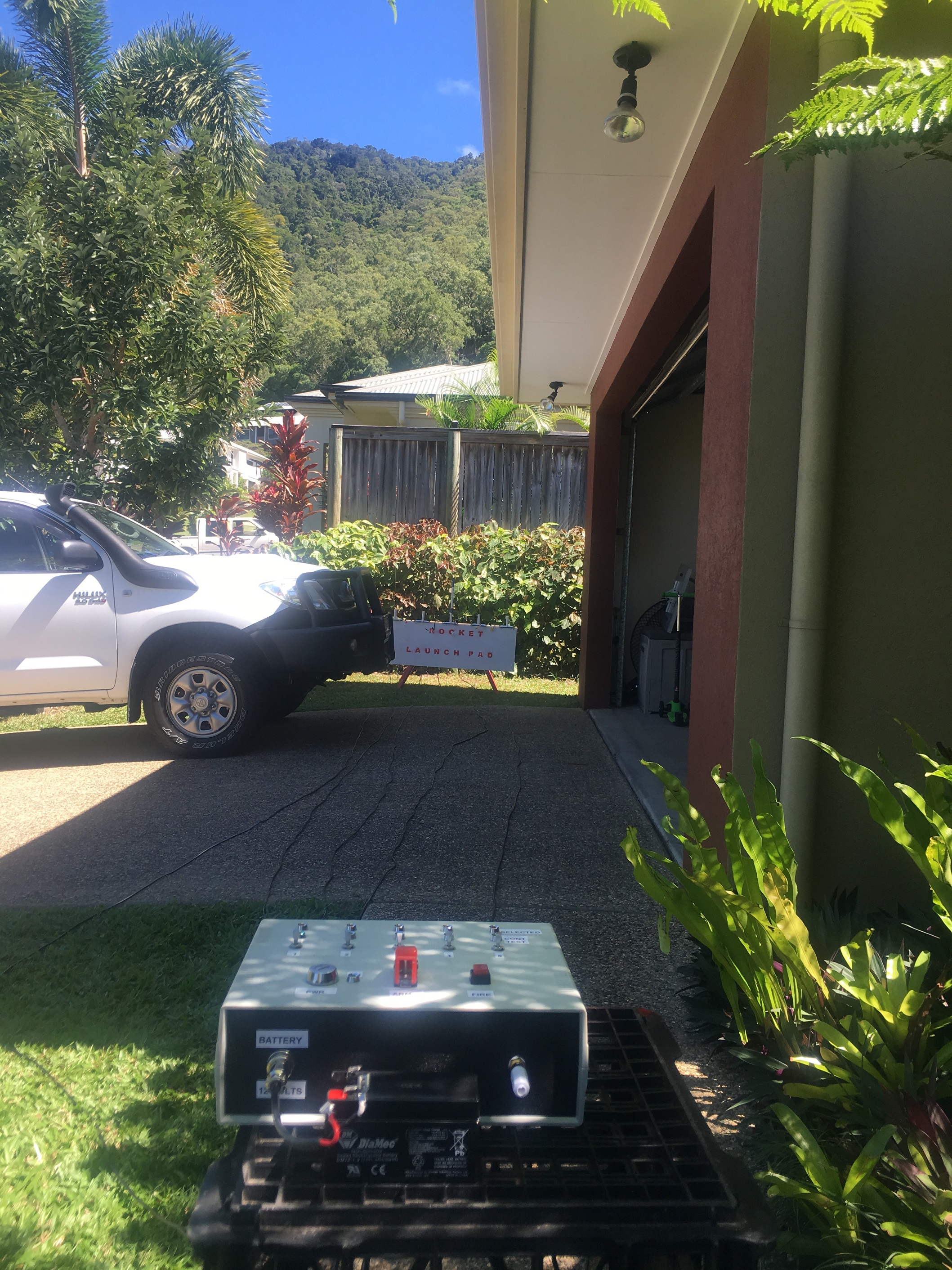
I’ve been working hard on a model rocket launch system, on the side. The system has the following specs:-
See the pictures below. Here I wanted to go through the paces of setting it up. I put some Nichrome wire and confirmed that it went red-hot for each rocket. I also did a test with an igniter to confirm that the current during continuity test will not result in a fire. Didn’t expect it to because the current is so small, but thought it would be a good test nevertheless.

I quickly performed some ‘shake’ tests of the payload on the desk. I managed to get a test run which generated NO Air pressure and temperature measurements!. Then next time I turned it on, it froze up when trying to detect the air pressure sensor. Not good!
So I decided to pull the system apart and check out clearances between the air pressure sensor and surrounding electronics. The components are very close indeed. I proceeded to put some sticky-tape on both sides of the sensor to reduce chance of touching electronics on either side.
I have performed the shake test (quite violently) twice now without any issues, so I’d say that the close proximity and the vibrations in the rocket caused a momentary short. I was lucky that the Gyroscope measurements still worked
Fixes I’ll be looking at putting in are:-
In any case, we’ll be completely redesigning the PCBs. So these problems will be resolved then.
It was decided on a whim to purchase and install a Air Pressure + Temperature sensor for the next flight. I purchased a :-
http://core-electronics.com.au/search/?q=MPL3115A2
I picked this because the pins were arrange in same order as the Gyroscope pins. So I had a relatively easy job of just soldering this on top of the Gyroscope.
Programming wasn’t as simple. The libraries that you can get from AdaFruit or SparkFun generally are one-shot, in that you need to wait a significant time for the sensor to return a value (in the order of a second). This is not satisfactory because we need to capture as much gyroscope data as possible. So we looked into a demo Arduino program by Sparkfun called SparkFunMPL3115A2AdvancedExample.ino. In this example it would get the sensor to collect data autonomously and at the end it would fetch all the data. It utilises a FIFO that can store up to 32 measurements of air pressure/temperature. We programmed our sensor to collect data every second. We allowed sufficient time at the end of the~8 seconds of gyroscope collected data (FRAM memory only has enough space for ~8 seconds of data) to get another 24 data points, by employing a 24 second delay. This should allow us to get 32 seconds (~ 3/4 flight profile) of air pressure and temperature. The program then stores this data at the very end of the FRAM.
We then modified the dumpFRAM routine to process the air pressure/temperature data to allow us to see what was recorded!
I tested this out by running up the hill with the sensor. Sure enough, the air pressure reduced as I ran up the hill. This extra sensor is a great addition to the flight. It will allow us to approximate the flight altitude over time, allowing us to compare it with the predicted flight altitude over time (generated from Open Rocket).
Below is an extra from a dump from the routine dumpFRAM.
2 151 79 32
RS: 0.02, -1.14, 0.01
2 151 115 216
RS: 0.03, -1.25, 0.07
2 151 152 144
RS: 0.02, -1.22, 0.02
2 151 189 72
RS: 0.04, -1.26, 0.11
2 151 226 0
, Temperature = ,26.7, C, Pressure = ,101.41, kPa
, Temperature = ,26.7, C, Pressure = ,101.41, kPa
, Temperature = ,26.7, C, Pressure = ,101.41, kPa
, Temperature = ,26.7, C, Pressure = ,101.41, kPa
, Temperature = ,26.7, C, Pressure = ,101.41, kPa
Here RS means Rotational Speed
The other lines with 4 numbers can be combined to produce the time in microseconds
At the end is the Temperature and Pressure. These are ~1 second apart.
We wish to test out the RLS systems and what better way than to do a real rocket launch. We hope to do a rocket launch next weekend of the Calliso Rocket and of another smaller rocket.
A lot of preparation has gone into this so far. We have done the following:-
I’ve sent off the “Relay PCB” design to pcbcart.com so that they can manufacture some Prototype PCB’s. A picture of Relay PCB is shown below.
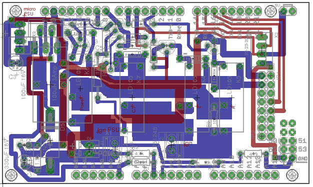
A lot of work into this board. Special attention was made to the width of tracks because some parts of this system need to be able to cope with currents up to ~4amps. [Despite best efforts, I had a track blow-out on the ‘Test’ board; so this really pushed this point home].
We also wanted this board to be complete, in that we don’t need to have any auxiliary boards for connecting/joining wires. We also wanted to connect the RFD900 modem directly and do away wit the clumsy cables. Note, there is not enough room to lay the modem flat on the PCB. We will have external plastic structure which will have additional level to screw the modem to.
One of the concerns with this board is vertical height and the direction in which connectors ‘connect’. We want to keep height to a minimum to ensure it can fit in a 60mm diameter rocket tube. We also don’t want cables coming in from the side as this will result in un-due strain on wires and all other assets (cameras, antennas, batteries).