Category Archives: Filament Winder

Nose Cone

A decision has been made to wind our own NoseCone. (Why Stop at the air-frame?)


The Design

Decided that a conical Nose cone is probably the best one to go for – because we can define the the surface with simple equations and thus create program that will move the resin bath, rotate the mandrel and turn the dispenser with “relative” ease. It is still a challenging task.

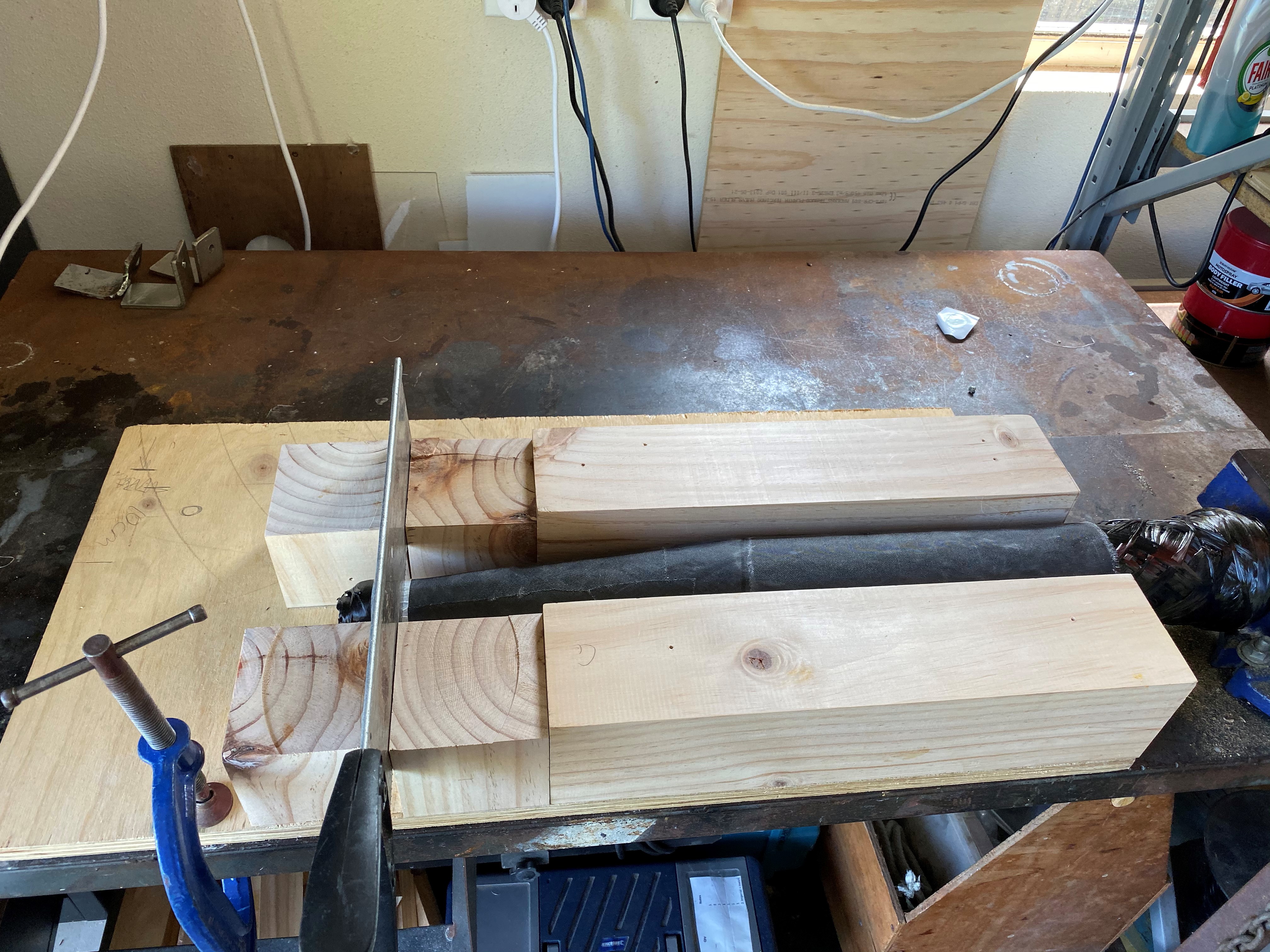
Mandrel Construction

We are going for 3-D printed Mandrel . Being so big, it has to be split up into many smaller pieces and installed on a 12mm Steel shaft.

WP 3D Thingviewer Lite need Javascript to work.
Please activate and reload the page.

I ended up replacing the last “12mm” cylindrical section and replacing it with a modified version. This was done because we realised that because the carbon fiber layup at the tip is going to be thicker than at the other end, we need to compensate for this with a narrower Mandrel – else we will NOT get the cone shape we are after. The Nose Cone would have been concave.

The Laydown of Carbon Fiber

Working out the mathematics for laying down the Carbon Fiber has been a challenge. The Carbon Fiber needs to follow straight lines (geodesics) to ensure minimal slippage of Carbon Fiber to produce the best Nose Cone possible.

There is more to the conical section of the Nose Cone, there is also the Cylindrical part. The Carbon Fiber from the Cylindrical part needs to “marry up” with the Carbon Fiber of the Cone part – no horribly bunching up. i.e. we need to continuous (well-formed) surface to wind around and for the CF Angle (with respect to the mandrel axis) to be the same at the interface.

Initially, we tried:-

  • 0 degrees
  • 90 degrees
  • 180 degrees
  • 270 degrees
  • 360 degrees (back to the beginning)

On the 5th pass, we move the Advancement angle amount. Then I thought it would be good to try and reduce the bunching of Carbon Fiber at the tip by having some adjacent CF. By having adjacent, we effectively double the width of the Carbon Fiber.

  • 0 degrees – 160mm from tip
  • 0 degrees – 165mm from tip
  • 90 degrees – 160mm from tip
  • 90 degrees – 165mm from tip
  • 180 degrees – 160mm from tip
  • 180 degrees – 165mm from tip
  • 270 degrees – 160mm from tip
  • 270 degrees – 165mm from tip
  • <<ADVANCE TWO x advancement amounts>>
  • 360 degrees (back to the beginning)

In 2-D it looks like: –

Sample of how CF TOW passes are done in 2D. Obviously there would be more.

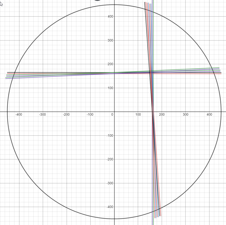
In the end, decided to not have adjacent CF laydowns and instead space them around the whole Nose Cone. This seems to produce a more even layup.

It was calculated that we needed 45.1 passes to cover the Cone. We decided to go for 48. This is a nice number and the additional passes ensure coverage.

We use a function to help “spread” the laydowns around the nose cone, so it wasn’t one next to the previous one.

So it was


Pass Place
1 2
2 15
3 28
4 41
5 6
6 19
7 32
8 45
9 10
10 23

etc.

So For Pass 1, we would move 2 x (360 / 45) = 16 degrees. Then for the Second Pass, we would do it at 15 x (360 / 45) = 120 degrees… and so on.

How did we calculate this?
We have two functions that we use to generate this value.

(1)
 y = (pass -1)* 12 + pass
(2)
 z = (y/48 - floor(y/48))*48 + 1

The second function just ensures that the offset value is the smallest offset value. i.e. it doesn’t rotate the spindle around excessively.
How did I get this function?
I just played with it a little until I got something that looks like it might spread it out AND very importantly, cover the ENTIRE mandrel after ~48 passes.
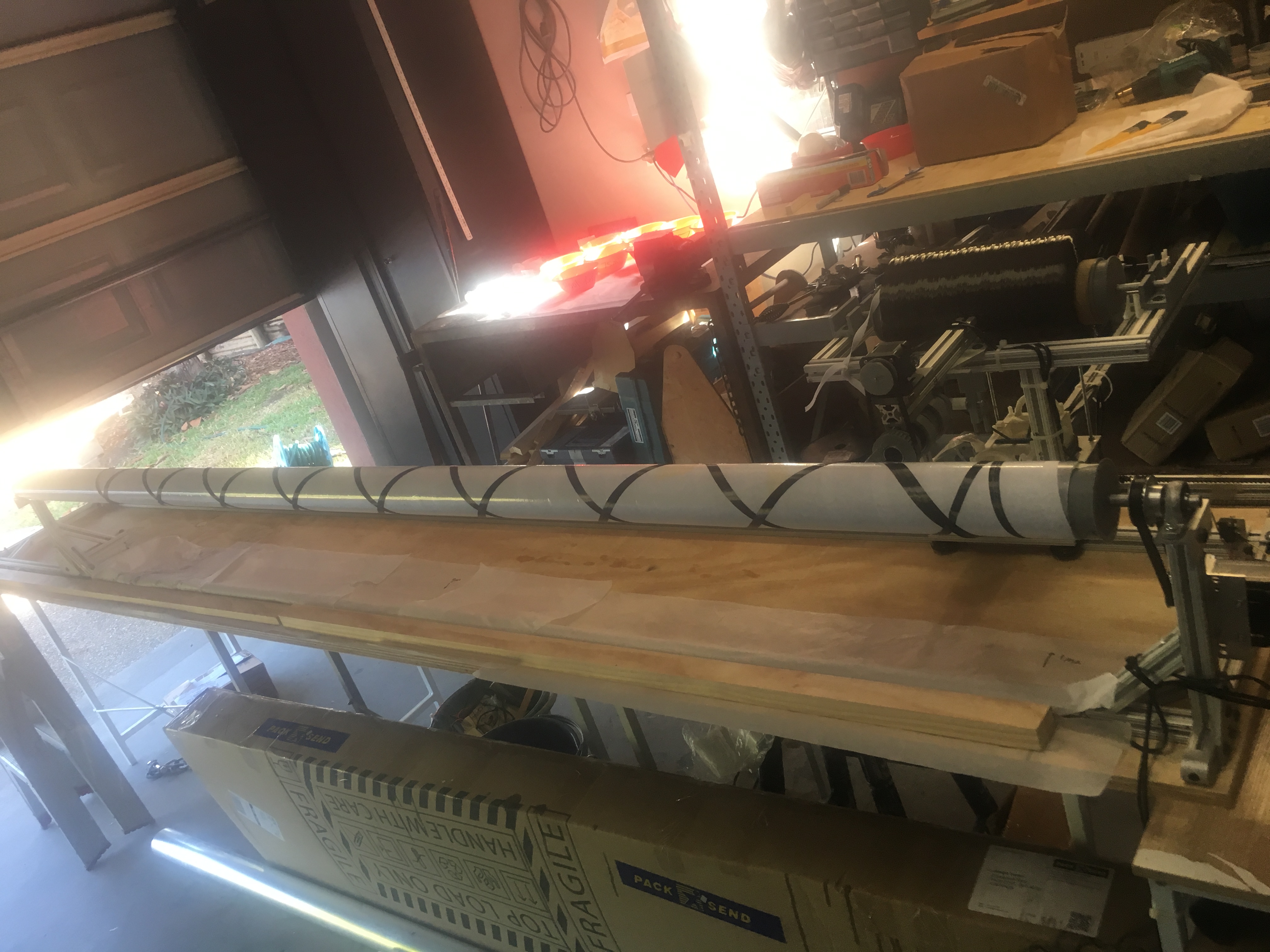
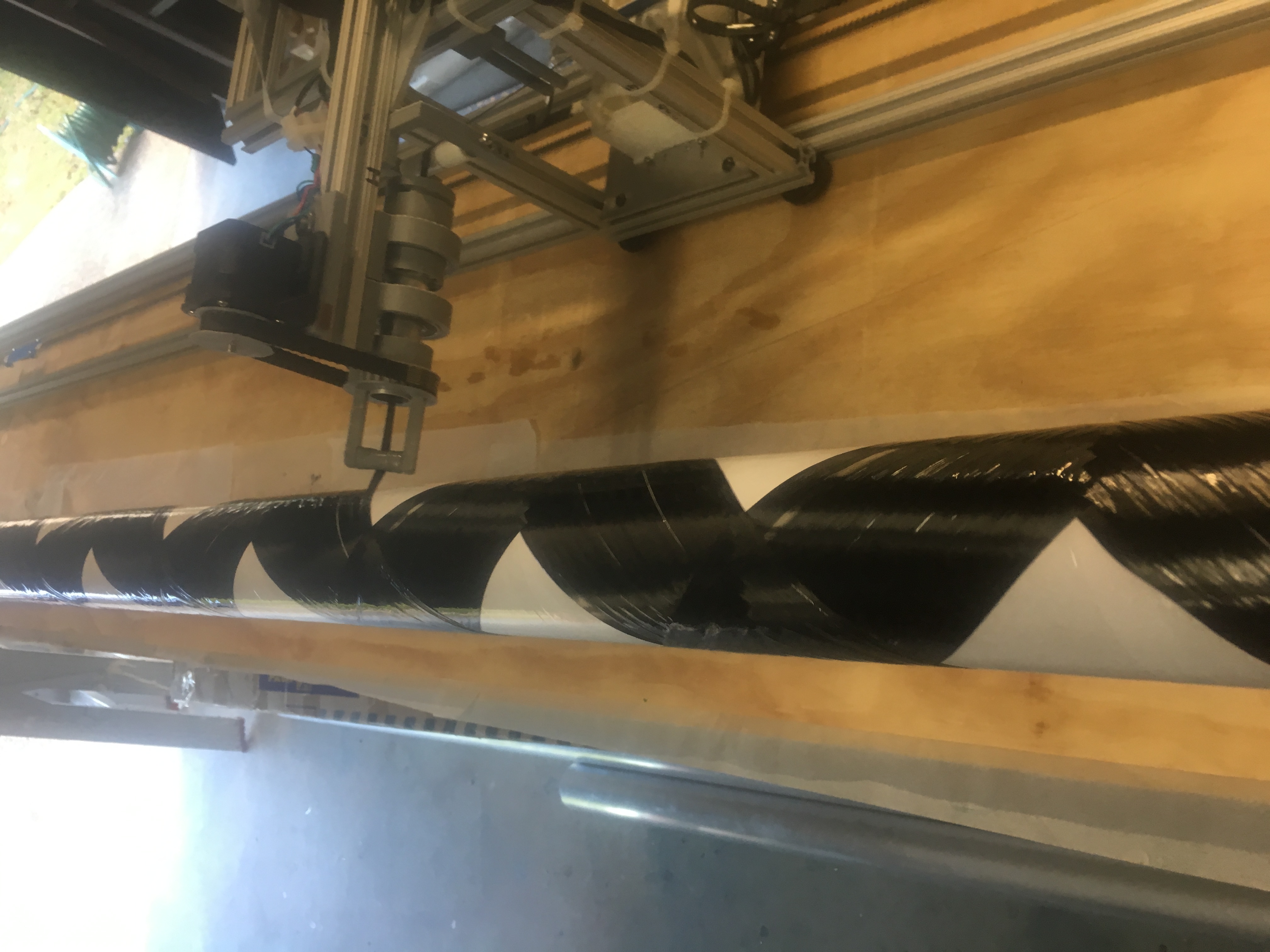
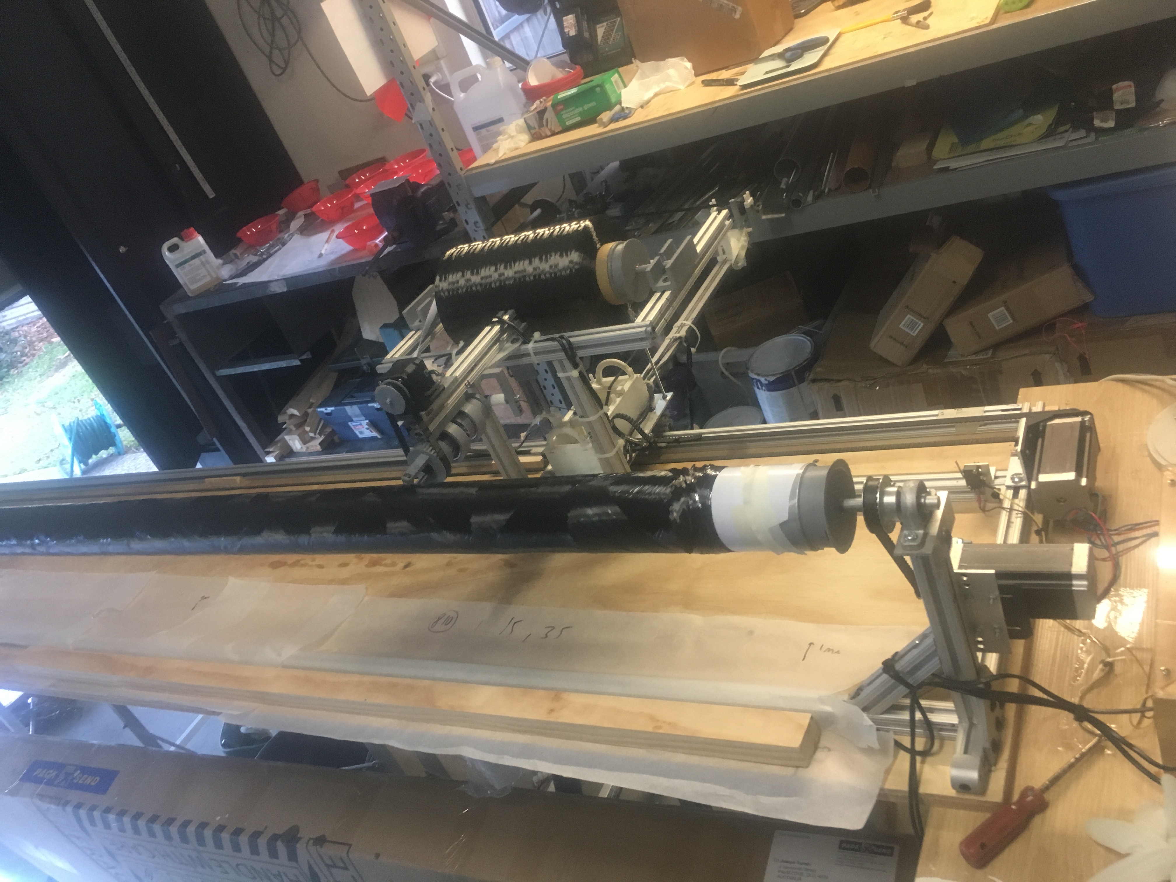
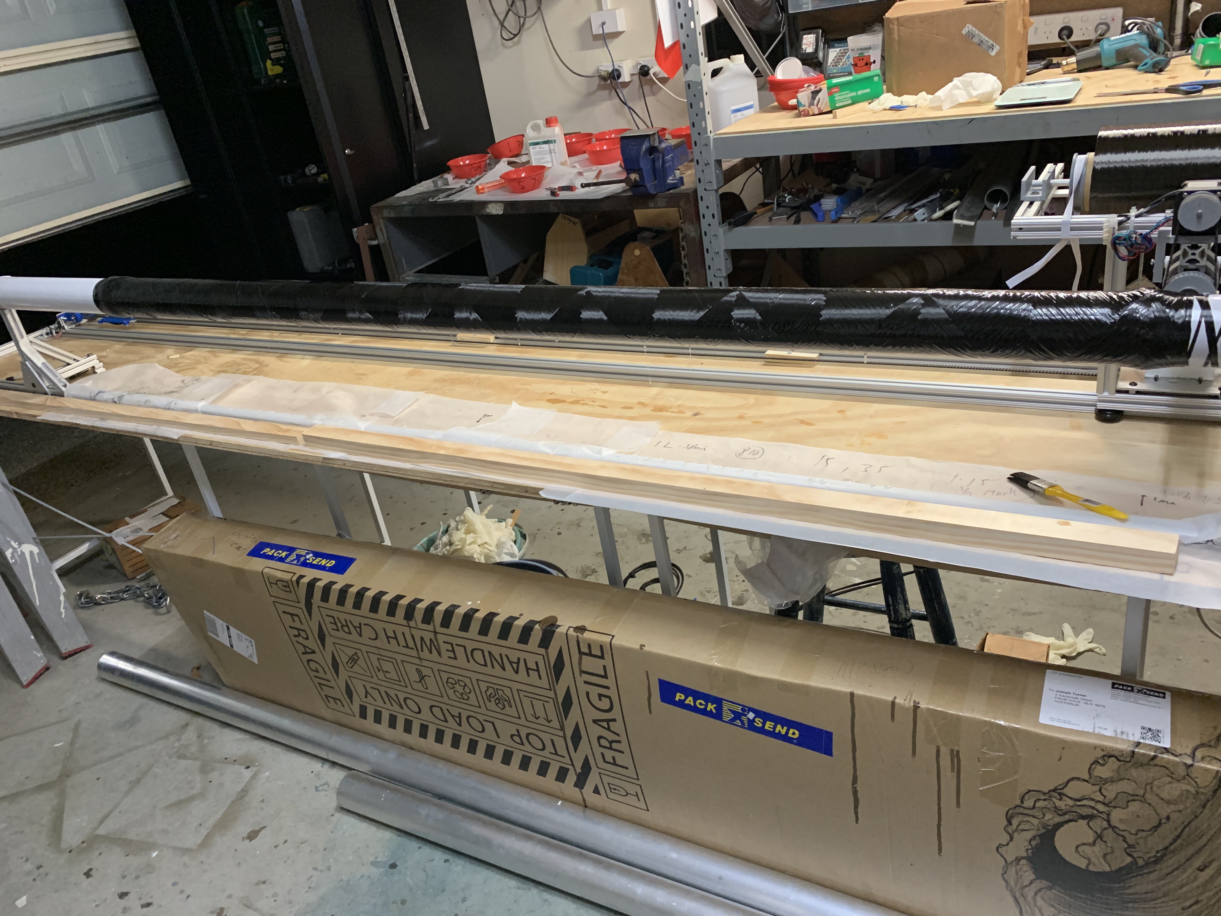
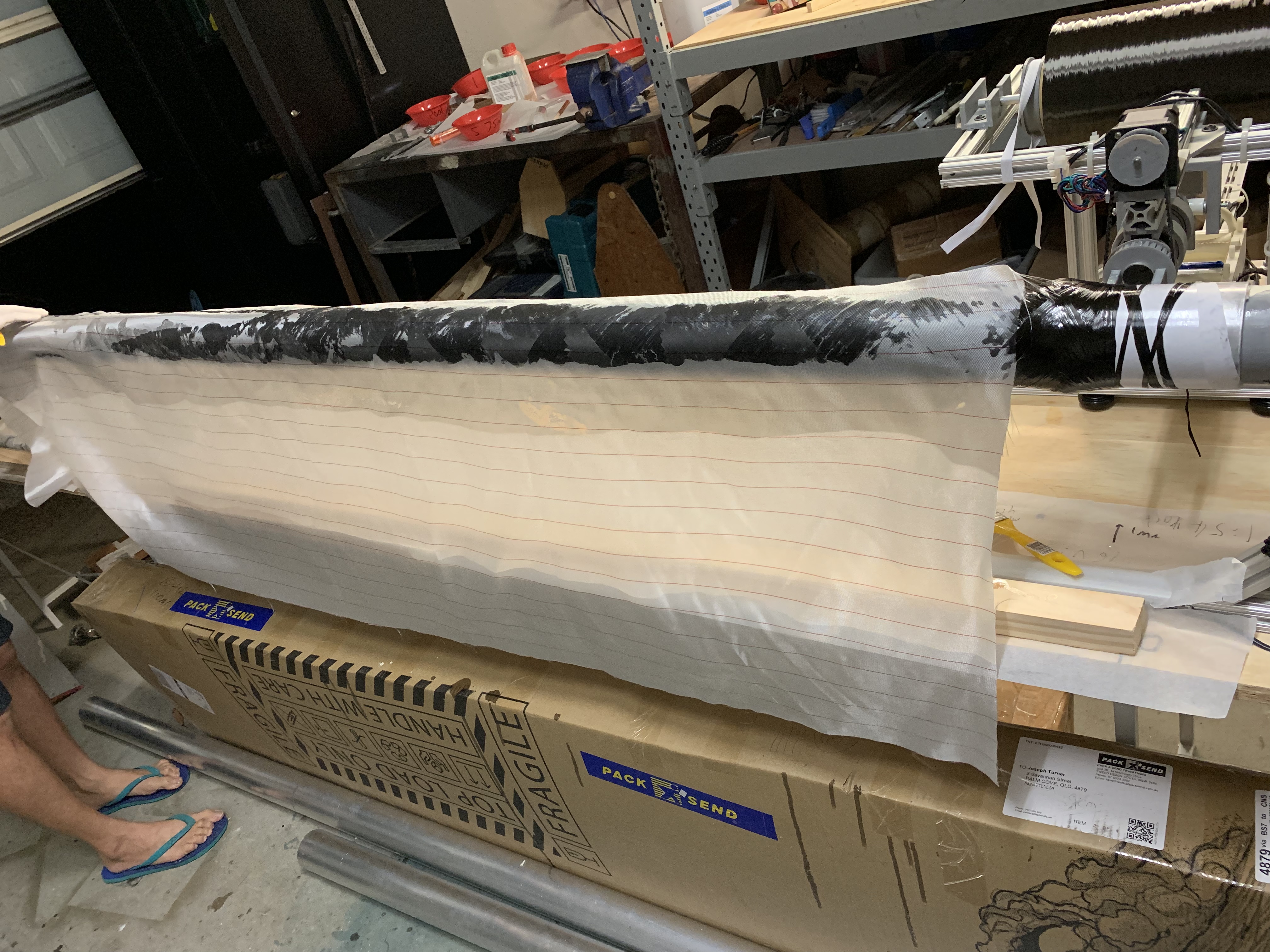
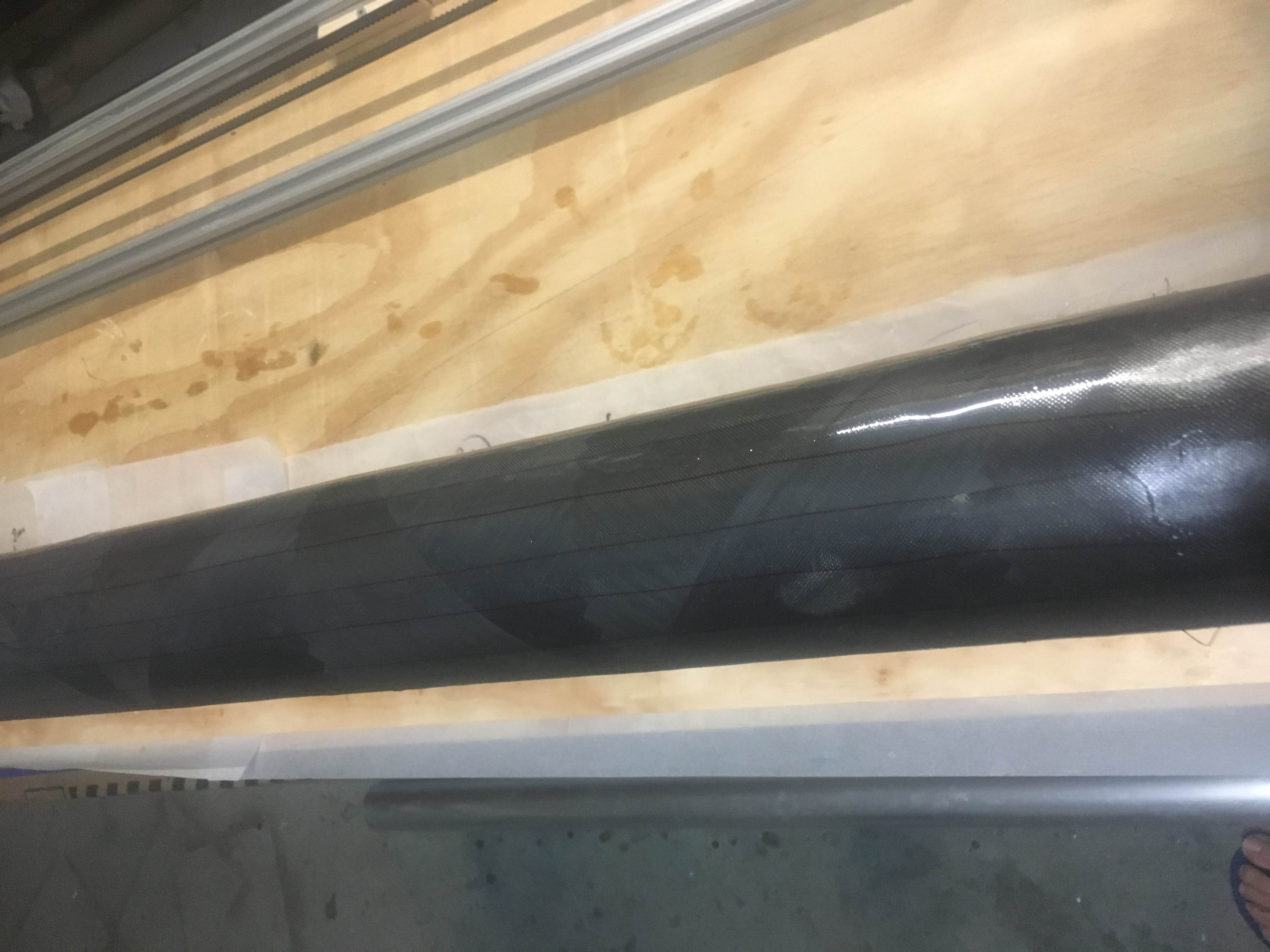
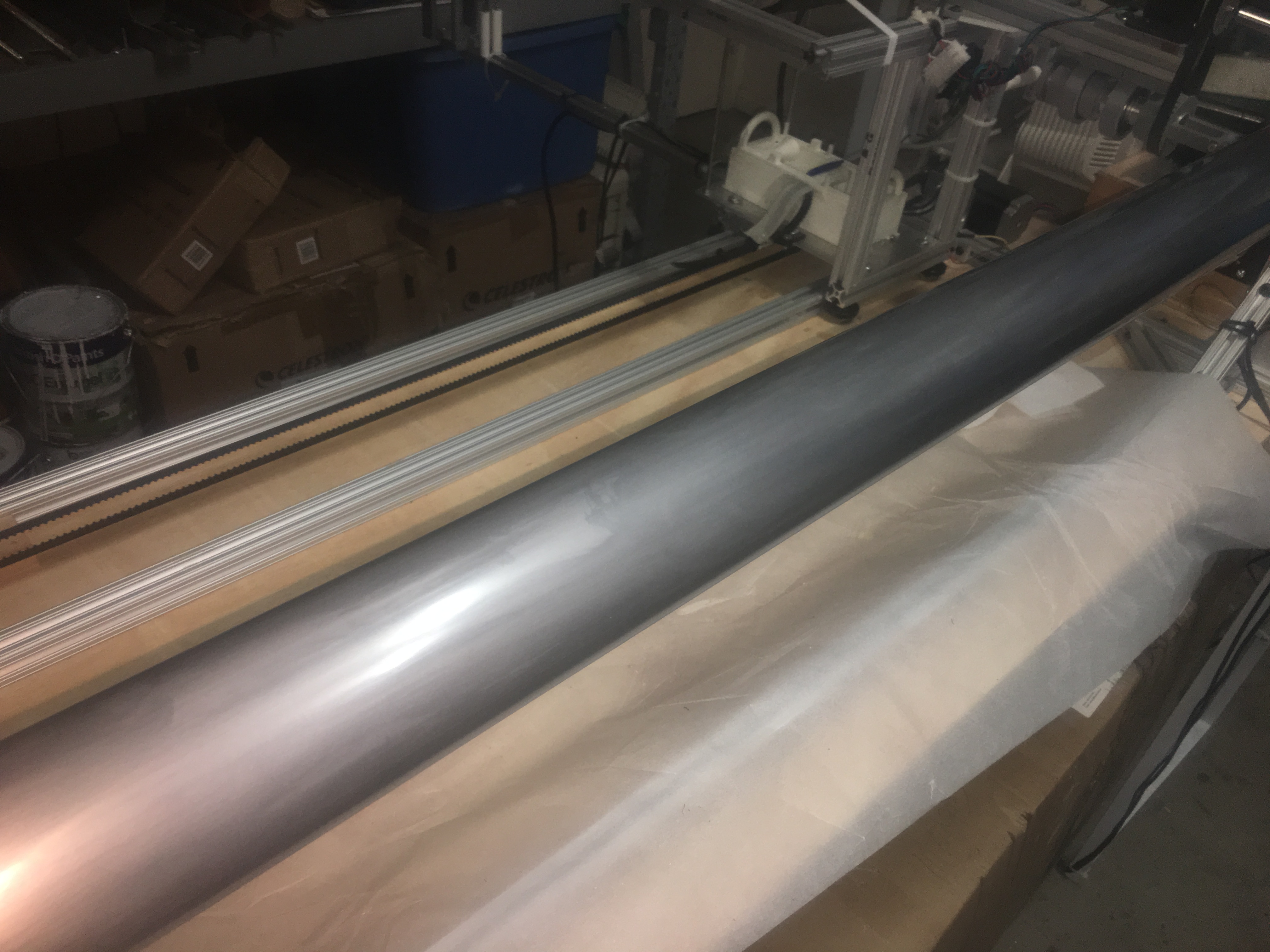
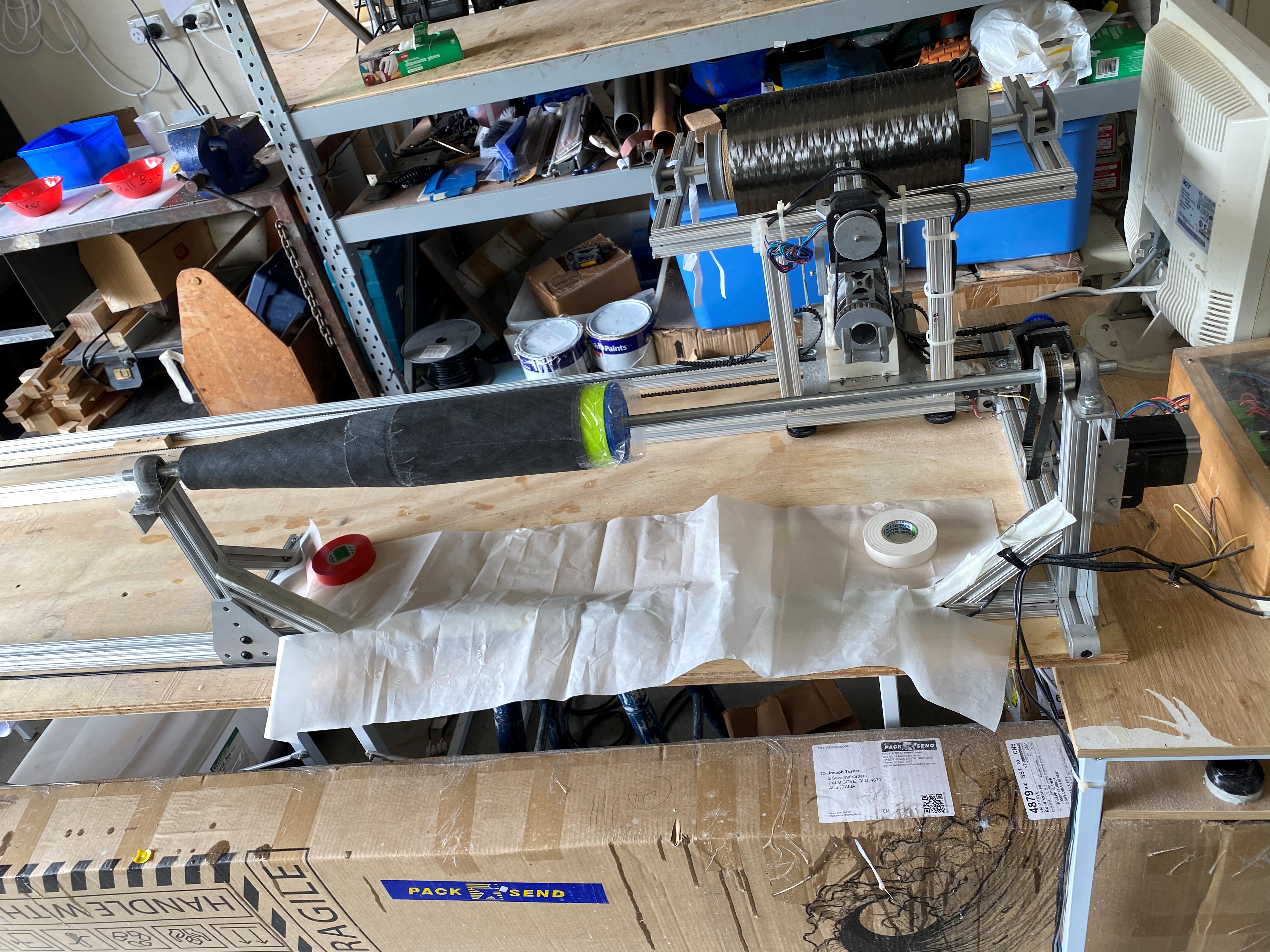
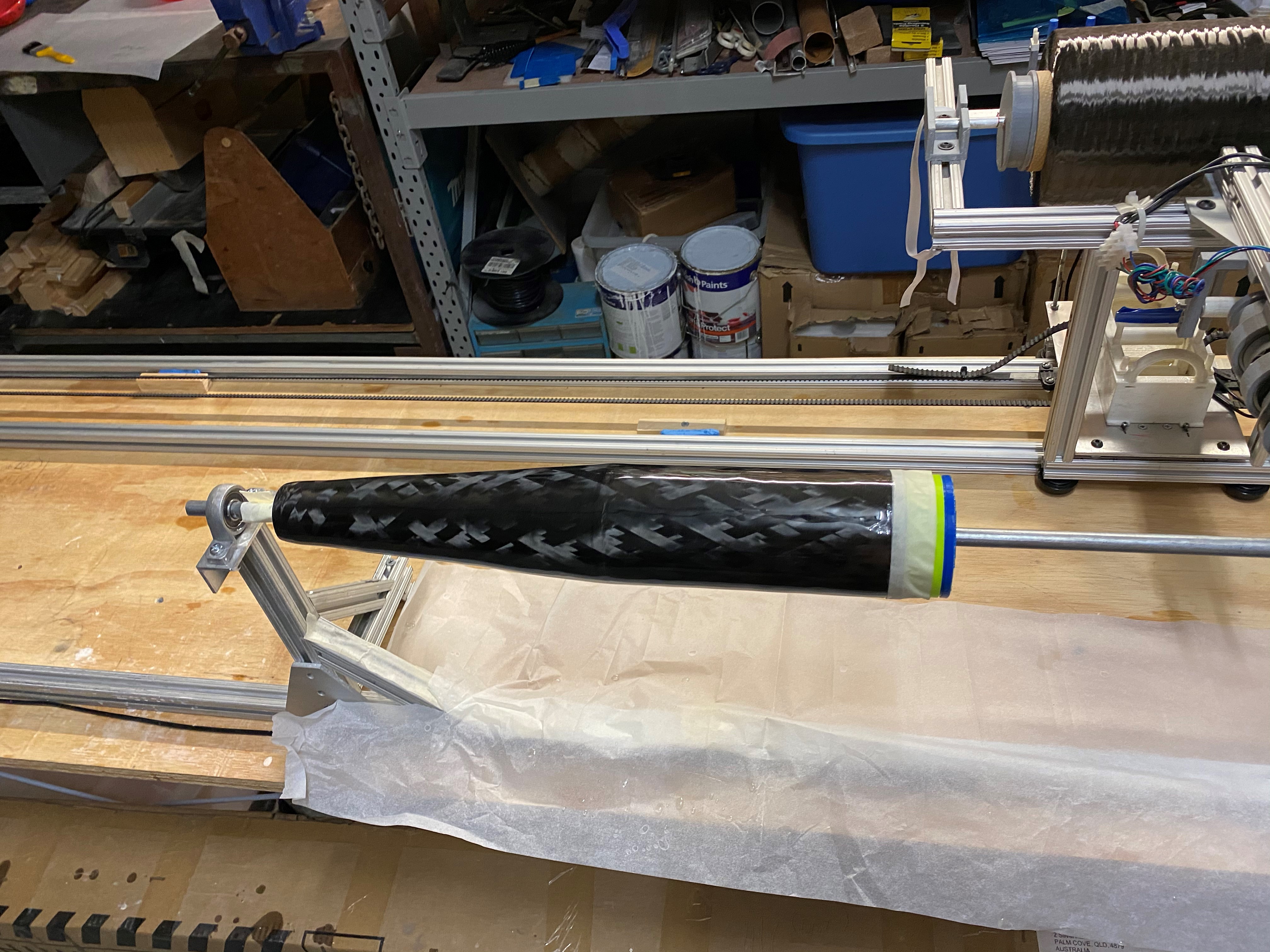
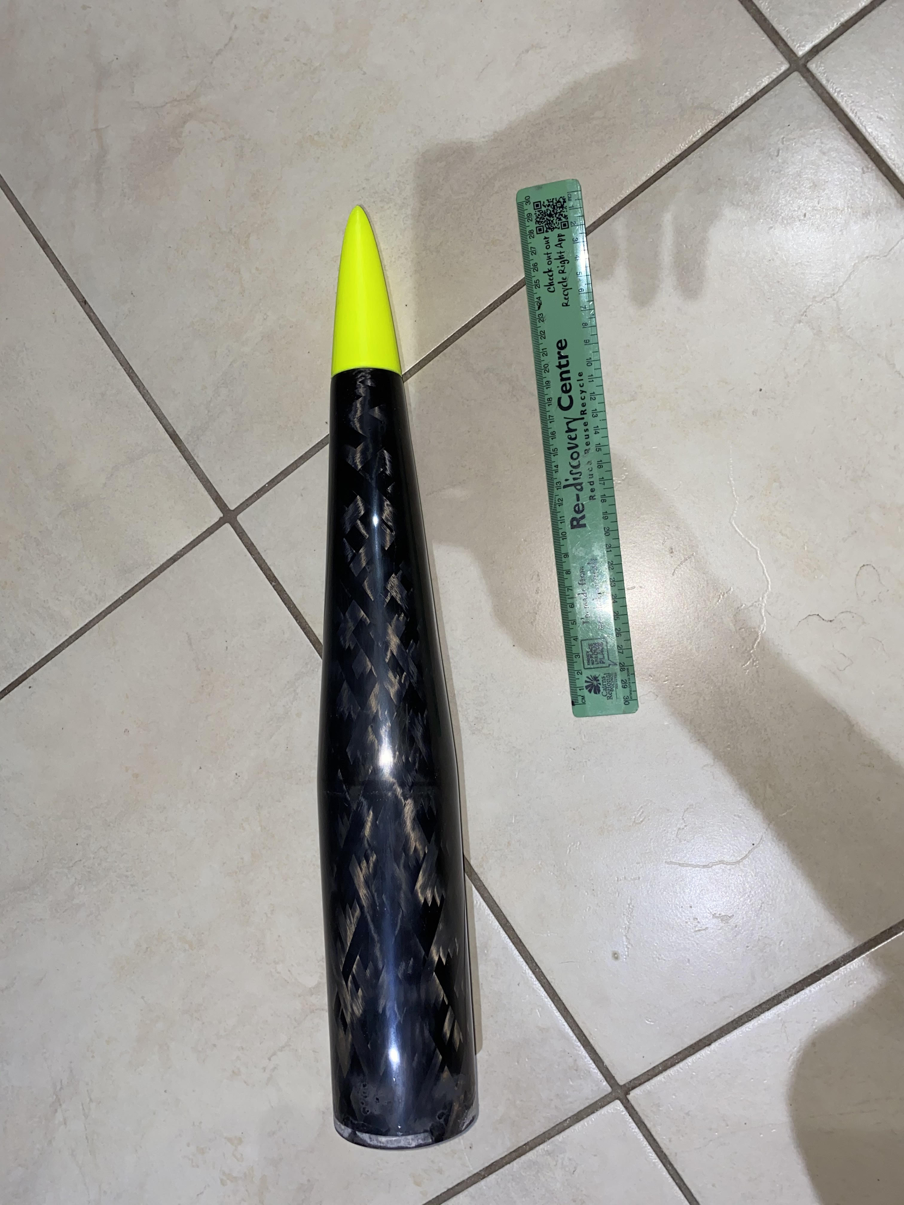
 

The Result

Here are lots of photos.


About 3/4 through the first layer.
At an advanced stage through the wind.
Applying Peel Ply.
Applying Peel Ply.


Inspecting the Nose Cone off Mandrel - Peel Ply still on.
Inspecting the Nose Cone off Mandrel – Peel Ply still on.
Finally removed Nose Cone from the Mandrel.
Removing Peel Ply.
Removing Peel Ply.


About to cut off tip in make-shift Mitre


Nose Ready to apply First layer of Epoxy resin finish.
Applied some Epoxy to the rotating Nose Cone.


Sanded Nose Cone - after first application of Epoxy.
Sanded Nose Cone – after first application of Epoxy.


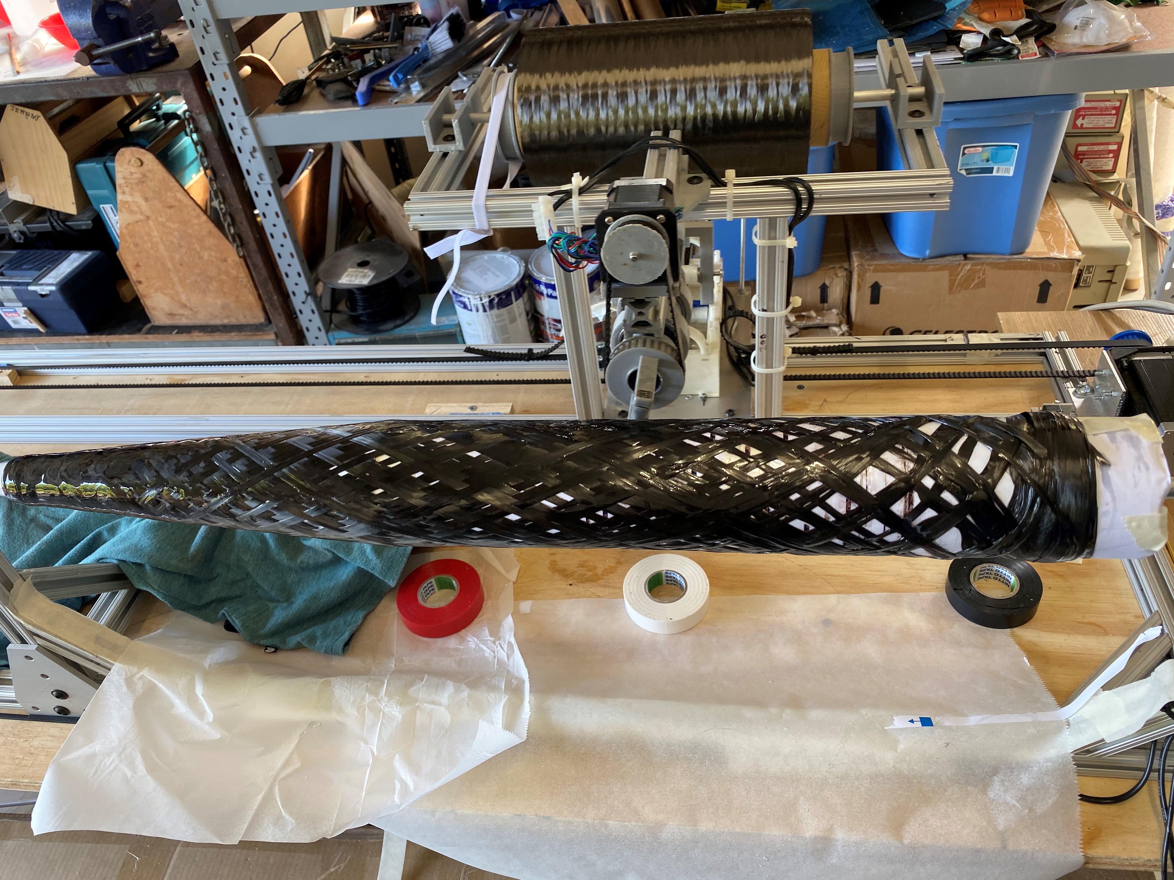
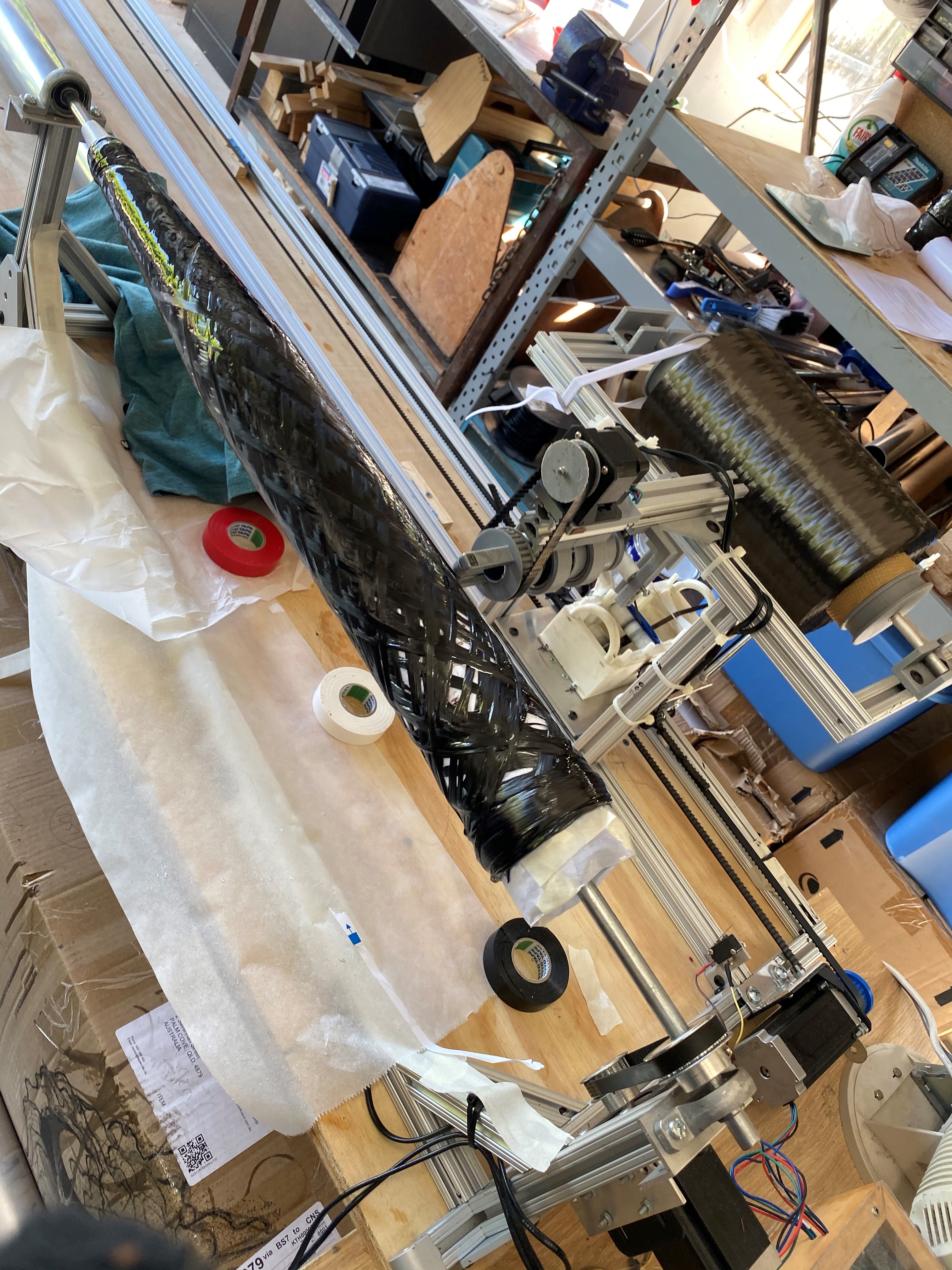
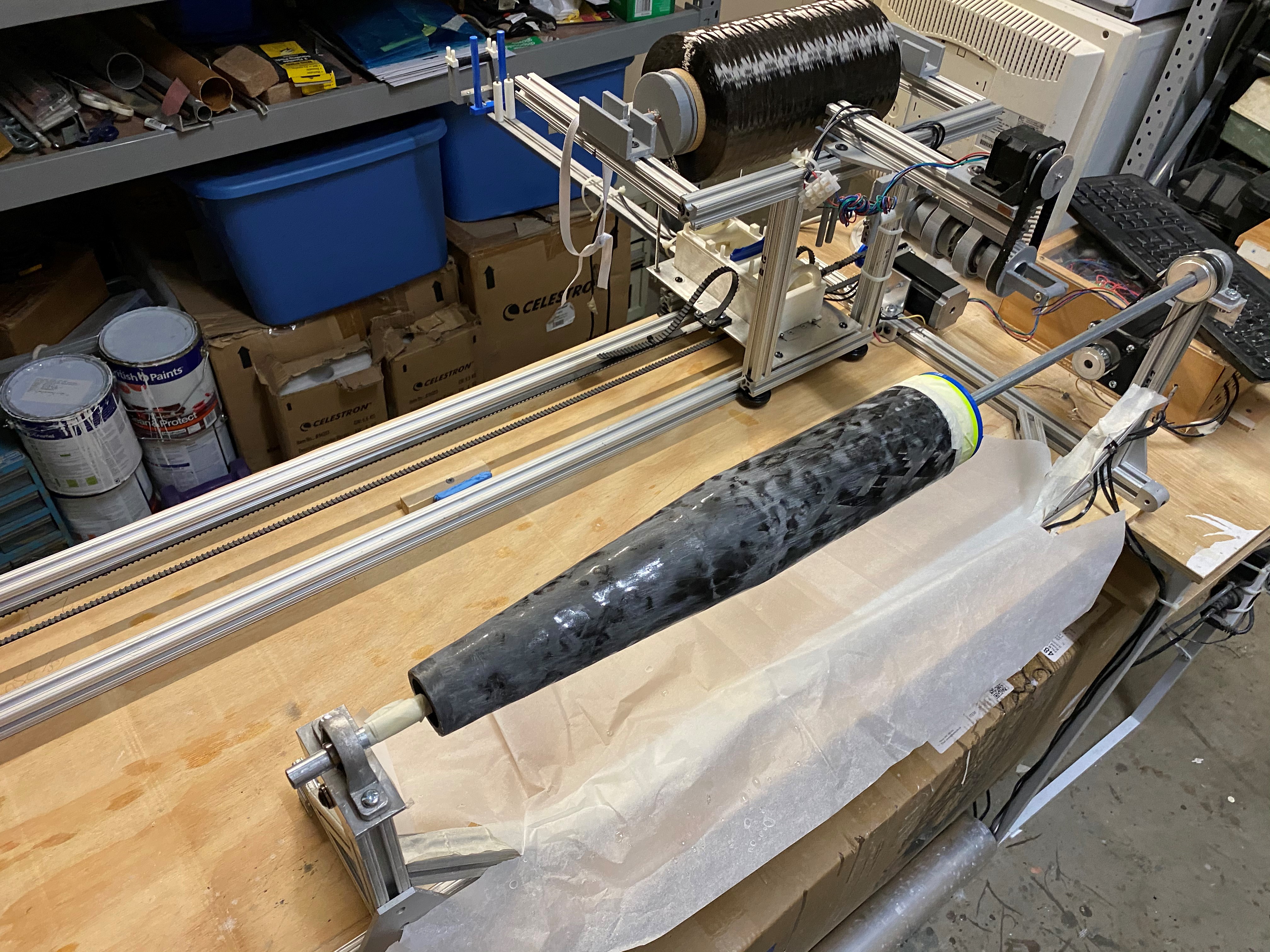
Repeated the above process two more times.

Then we 3-D printed a nose Cone tip – a parabolic one that results in a pretty good looking nose cone. I chose parabolic because it results in a rounded point and reduces the total length it would be, should it need to be conical (229 mm to about 108mm).

y = 0.238 * x * x

That x is between 0 and 22.3.

When the Epoxy shrinks, it is approx 0 to 21.65mm.

Nose cone after 3 applications of Epoxy and 3 sanding sessions - finally with plastic TIP (to check out size)
Nose cone after 3 applications of Epoxy and 3 sanding sessions – finally with plastic TIP (to check out size)

Obviously the final tip will be Aluminum and we will trim off some of the bottom of the Nose Cone – it doesn’t need to be that long.


2 Meter Tube – The Great One!

I’ve managed to create a single layer tube ~500mm long using Peel Ply to finish off the layer. It worked quite well and was easily able to take it off. I decided it was time to create a 2-meter tube! (With Peel Ply)


Preparation of Aluminium Mandrel

I’ve purchased 2.5 meter long Aluminium tube and I’ve done ALL preparation. Preparation includes: –

  1. Sanding down tube with ever increasing Grit sizes
  2. Polishing with Brasso
  3. Waxing it with TR-108
  4. Visual inspection
  5. Set-up on Mandrel and align with respect to Carbon Fiber Delivery Head


Paper Liner

Then I wound paper around the entire tube very carefully. I have gone for the following approach: –

  1. Use 2 x 1 meter  strips of paper , 1cm wide (reinforced with packing tape) as spacers between Aluminum Mandrel and paper winding.
  2. Wind the paper in 3 sections, so we don’t get too much double up on paper, as pitch changes
  3. Use additional paper winding to connect three pieces
  4. Wrap packing tape over ENTIRE length of paper windings, going back over it to ensure good adhesion and no gaps
  5. Removal of the paper strips
  6. Test that we can move the paper Liner

I’m able to move the liner with a single hand. While it isn’t easy, it is clearly moving without serious obstruction/opposition. I’ve noticed that it is very important to PULL the liner, not push, because if I push, it can bunch up.

The result is: –

  1. A paper liner that slides and can be removed BEFORE any Carbon Fiber is applied (in initial winds, it was so tightly wound, even with no Carbon Fiber, it was impossible to remove WITHOUT the use of Dry Ice
  2. A paper liner that is smooth on the outside – ANY imperfections show on the inner side of the Carbon Fiber Tube
  3. A paper liner that is about the same thickness along the whole section. True, some parts might be an extra 1 or 2 paper widths thicker, but this is a tradeoff for smooth liner that can be removed.

The Big Day!

What happened

There was about 3 hours of preparation: –

  • Making sure the winder was in suitable health.
  • Preparing Epoxy
  • Filling out the “worksheet”
  • Performing the calculations
  • Cutting the Peel Ply to length


Then there was the wind: –

  • The Wind of Carbon Fiber took 2.5 hours – About 40mins per layer.
  • The Peel Ply took about 1 hr
  • The cleanup about 2 hours.

IT was truly a massive effort.

It wasn’t smooth sailing. The Carbon Fiber got caught in the rear roller several times and fortunately was able to recover it and keep the winding going. Very fortunate indeed. I have since created higher barriers, closer together to prevent this from occurring again.

Here it is in pictures

First layer of 2 meter Carbon Fiber Tube.


About 30 passes of First layer.


Finished the 4 layers of Carbon Fiber


Immediately before Peel Ply wrapped around.


Peel Ply partially wrapped around.


Closeup view of Carbon Fiber Tuber after Peel Ply applied. Notice the distinctive pattern.


Removal of the Carbon Fiber Tube from the Mandrel

Here is a movie of the removal: –

Post Wind

Since creating the winding, we have verified that a 75mm case will fit inside the tube. This is not unexpected, but needed to confirm. It is a magnificent fit. Easy sliding, but no perceptible rattle.

The next step is to give it a better finish. This will likely be several layers of Epoxy and then a lot of wet sanding.

Preparation of the Surface

After the massive issues with the previous wind – not being able to remove the tube, I decided drastic changes needed to occur.

The aim is prepare Mandrel so we do NOT need to use Dry Ice to remove it.

The Solution

The Solution is several fold: –

  1. Do not heat the shrink tape for more than 10 minutes. This will ensure we don’t accelerate curing excessively, and we still get a chance to squeeze out excessive Epoxy
  2. We use a combination of Mould Release Wax and a “lubricant” to make removal easier.
  3. Only let the Curing go for as long as required before removal. i.e. after 6 hrs (guess), remove the tube. i.e. Don’t wait 12 hours.

We look at each of these points in more detail below.

Shrink Heat Tape

The curing occurs faster as you heat the epoxy. As the Epoxy cures, it shrinks and gets ever harder to remove from the Mandrel. Why I had to heat it for 4 hours is beyond me. All I wanted to happen is for the Excess Epoxy to be squeezed out. After ~10mins, the Epoxy is not fluid enough to be squeezed out, so the heater should be turned off and Mandrel be allowed to rotate for several hours


Surface Preparation

I wish to use TR-108 – a wax that is applied to the mandrel.

TR-108 General Mold Release

The lubricant  I wish to use is Graphite (product from Bunnings)

Lubricant to be applied on top of Wax (between Wax and the cash register tape).


The steps I followed on the next test run are:-

  1. Water/sand from 400 grit down to 2000grit
  2. Use Methylated spirits to clean surface
  3. Use Brasso with paper towel to produce finer finish
  4. Use Methylated spirits to clean surface – Do this a number of times to get VERY clean
  5. Apply 7 coats (1 hr in between) of TR-108. I would apply thin film with clean paper towel, from one end to the other. When I finish, I go back the beginning end with a CLEAN cloth and polish. I polish three times, each time with  a new Clothe. That is ONE layer done
  6. The next day I do ONE more coat of TR-108 wax – same procedure.
  7. Next I get some Graphite (powder) and sprinkle over entire Mandrel.

Below is a photo of Mandrel with 7 of the 8 coats of Wax applied.

Mandrel after 7 coats of TR-108 Wax.


I’m very happy with how it is going, but won’t be sure of effectiveness until we have to take the carbon fiber tube off.

Winding a 1.8 meter tube

We finally managed to get time to wind a tube. Total length of tube is about 1800mm. Usable length is about 1600mm.

This was the “FIFTH” wind and the most successful to date.

Specs

Layers are

  • 45/-45
  • 30/-30
  • 30/-30
  • 45/-45

I choose this layup structure because analysis suggests it should be able to easily handle L3 rocket design I have in mind.

We used Renlam K3600 Epoxy and we used 50mm heat shrink tape to finish off the wind (squeeze out excess epoxy).

The Wind

The wind took two hours of winding and involved mixing 6 bowls of Epoxy (110ml epoxy in each bowl). about 600 meters of Carbon Fiber was rolled, almost perfectly.


Video of the job

Here is a video of the job. I put some music in the background!


Enjoy!

Removal of the Tube

It hasn’t all been smooth sailing. I’ve only been able to pull it off the mandrel but about 25 cm. This involved using the car, chain, dry-ice and a very stable tree.

Later I put a 12mm bolt through the Carbon Fiber and attached to car via 800kg rated chain. On the other end of the tube (on the Aluminum Mandrel) I attached another bolt and chain around the tree. The Carbon Fiber Tube broke probably about 500kg load (complete guess). The load could not be distributed across the carbon Fiber tube easily and it ripped it with ease.

I had a feeling this would happen, but I felt I had to give it a go.

This bit has been very disappointing; but it has been an incredibly excellent learning exercise.

Filament Winder: The Gears

Gears and where they are used

We utilise XL sized gears for all axis :-

  • The Spindle
  • The Carriage
  • The Filament delivery head

Issues experienced

We had severe issues with the gears/belt that moved the Carriage.  We discovered that it was skipping steps and as a result the carriage would be ahead (or behind) where it should be.

Essentially, we had badly mounted gears at the stepper motor and at the idler end. The mis-alignment wouldn’t normally be a problem, but because of the large length of the Carriage belt, the engineering shortcomings were amplified.

A lot of this was due to my inexperience with gears, some due to badly machined gears. The main problem was mounting these gears on to motors and axles.

We got by in the end.

Carriage Stepper motor

We eventually got a steel XL gear and had a 10mm bore drilled by a local machinist on their lathe. Unfortunately, we should have asked them for a tight fit on to the Stepper Motor and provided them the Stepper Motor. Better still, we should have asked them to cut out a keyed key-way to fit the motor.

We have managed to improve the mount by using tape and careful placement of screws to mount the gear on to the shaft. It isn’t pretty, but it should be functional for now.

Below is a photo of this in use.

Stepper motor and gear that drives the carriage.

Carriage Idler Axle

We have at present a 3-D printed gear at the idler end.

The Idler, idler enclosure, belt, bearings all installed.

One of the idler gears we purchased was drilled well, but the gear was not machined correctly. The other idler gear was hand drilled with drill press and the hole isn’t sufficiently centered. The 3-D printed gear is doing very well at present. It has been treated with Acetone vapours and is so smooth/hardened sufficiently to not adversely affect the belt condition; atleast not so far.


Carbon Fiber Delivery head

We printed our own gears for the Carbon Fiber Delivery head. 3-D pics of these are shown below.

WP 3D Thingviewer Lite need Javascript to work.
Please activate and reload the page.

We used these 3-d printed gears because they allowed us to easily come up with design that could be fitted on to the aluminum shaft, which the carbon fiber runs through.

Here is what it looks like in real life.


Z-Axis of winder. This helps to present the carbon fiber at the correct angle.

Spindle Set-up

We have 20 teeth gear mounted on the shaft stepper motor and 30 teeth gear mounted on the 12mm shaft that ultimately drives the mandrel. These were drilled using a drill press and so the bores are not perfectly aligned. The alignment is not detrimental to the operation of the spindle.

Below is a screenshot of the set-up


Gears to drive the mandrel


As you will notice, the stepper motor is mounted on to the post. This was not actually by design, but out of necessity because the wrong belt was purchased. This has worked out well nevertheless, by reducing use of  important realestate on the bench.

Filament Winder – The Idler

The carriage is belt driven unit with stepper motor at one end and idler gear at the other end. We discuss the design of the idler in this post.

Overall Design features

The idler gear has evolved considerably, especially since the alignment issues. We use:-

  • Bearing enclosure (3-D print)
  • Two sealed bearing (Metric, 6mm bore)
  • 1/4″ Aluminum axle, sanded at each end to accept the Metric (6mm) bearings
  • 3-D printed gear
  • Two large washers
  • Two smaller washers.

These components are then attached to Aluminum right-angle bracket that is secured to the 1010 bar at the end of the winder.


The Bearing Enclosure

Below is a 3-D view of the Bearings enclosure.

WP 3D Thingviewer Lite need Javascript to work.
Please activate and reload the page.

One can see where the 2 bearings are mounted. This is interference fit. There are three holes which are used to attach this to a aluminum bracket. One can tighten these three bolt/nuts to increase tension in the belt and we can adjust as required to balance the belt.

We have sufficient gap between two bearing compartments for ~22mm gear and several washers to assure there is no belt/ABS plastic abrasion.


The Gear

We purchased several gears, but had problems getting them working – some gears where duds and other gears had holes drilled in them that were not working. In the end, I printed a Gear. A lot of effort went into this gear – mostly trial and error.

Below is what we printed.

idlerGear

We also extended the ABS out a little on each side (the green area) to ensure that any abrasion did NOT occur on the gear teeth. The reasoning is that if we don’t, the teeth will deform from heat and this will help degrade the belt teeth.


After we print it, we treat it with acetone. This hardens and smooths the surface which is EXTREMELY important to preserve belt life.

Everything connected

Below is a photo of all the parts connected and working together.

The Idler, idler enclosure, belt, bearings all installed.


Issues Identified

Destruction of the idler gear

I have noticed that after some use of the winder, a grey powder is being deposited at one end. Please see below.

Notice the powder residue on the wood bench.


At first I thought this might be the belt, but now I suspect it is these “end” pieces that are grinding away. For this reason, I think I’ll need to replace the idler gear occasionally, e.g. every 1 or 2km of filament.


The Belt

The belt ideally would sit in the middle, but it doesn’t. Instead it sits at one end. We can adjust screws to the back of the idler to encourage it to move in one direction, but it eventually goes back to the LEFT position.

I have thought of having fixed guards and this MIGHT be the way to go, however concerns with belt abrasion against the gear have put me off this. For now, we have stainless steel washers to reduce chance of abrasion of belt. So far it has worked well.

Filament Winder – An Introduction

A Short Introduction

I’ve decided that I don’t just want to build a rocket, I wish to acquire new skills and capabilities and potentially be part of the bigger picture – potentially supplying Carbon Fiber Tubes.

The most rewarding way to do this I’ve decided is to design and build a Tube winder, much like the one you see at http://x-winder.com.

What the Filament Winder does

The Aim of a Filament winder is to very accurately lay down Carbon Fiber tow (or any other fiber) on to a mandrel. The filament travels through a bath of Epoxy.  Usually multiple layers of Carbon Fiber are wound on to the mandrel at varying orientations and at the end, some tape is wound over the last layer. This tape is special heat-shrink tape that when heated (with a heat gun) causes the tape to shrink and remove excessive epoxy.

After several hours of curing, the tube is then post-cured by placing it in a temperature controlled “oven” which helps to improve the properties of the tube under temperature.

Components of the Winder

The framework

The design is similar to X-Winder, but not based on it.  We have used 80-20 components before and the lack of a complete machine workshop makes this an intelligent choice for the bulk of the design.

Motion components

We use Stepper motors from OMC, which are affordable, reliable. These are Chinese brand and considerably cheaper than alternatives.

Drive components

We have decided to use XL gears and XL belts to drive all the components. We are coming to the realisation that the large XL belt for the train might a little under-spec, but it has worked ok so far.

Controller

We are using LinuxCNC on an old DELL workstation to drive the Stepper motors. It is free and easy to use. I wanted to avoid crafting up my own electronics/code to do what was already being done well by LinuxCNC.

Wind Code Generator

We still needed a means to generate the codes that LinuxCNC would follow to control the motors, to get the desired outcome. We decided to “home brew” a PHP application (web-based) to generate this code based on inputs on a webform. This PHP application resides on the DELL server.