Category Archives: Rocket Building

Building of a rocket

Testing the Cable Cutter

The Cable Cutter

The Cable Cutter I purchased from Aerocon Systems has cambered edges as shown in photo below.

This should have a very sharp cutting edge...a concave hole.
This should have a very sharp cutting edge…a concave hole.

According the supplier, this is normal of these cutters now and is on purpose because the Aluminum cartridge gets damaged from the sharp edge of the piston when too much Black Powder is inserted.

Creating a Cutting Edge

I decided that I would introduce some sharp edges because it just didn’t cut on my first test; and if it doesn’t cut the cable tie, it is of no use to me. So I drilled about 3mm into each end with a 2.5mm drill bit. Then I used a counter-sink bit to create a bit of a ‘crater’ with a sharp edge. See photo below.


3mm deep hole drilled with 2.5mm drill bit.

Precise steps were:-

I did this in the vice, very carefully using Aluminum brackets to not distort the steel piston. I marked the center point using pencil under magi light. Then I used punch to mark the center.

I went straight to the 2.5mm drill – special tip and used cutting fluid. It drilled just fine. Then after drilling to a depth ~3mm I used a countersink drill bit to go about 1mm in, to get a “cutting edge” just inside the main diameter.


Assembly

I assembled as follows:-

First goes the O-ring.


Threading the cable tie into the blue cylinder.
Slotting in the Piston.


Next I straighted out the e-Match and took the red plastic protector off it. Then I rolled on a small O-ring. The O-ring has two functions:-

  1. To help seal the cylinder, reduce amount of gas coming out
  2. To stop shorting of the igniter contacts on the hex screw end bit.
Close up view showing the O-ring.
Everything fitted and plenty of hot glue melted on to end to ensure no gas comes out the rear.

I then melted some hot glue on the end.

Then afterwards, I removed the screw bit…and put the measured 0.1 grams of black powder in.

0.1 grams of black powder measured.


Then I screwed it back together again.

The test

Below is a video of the test.


Very happy with it!

The Engine Block

I’ve progressively refined the design of an engine block. This is a device that sits inside the air-frame, about 1/2 way along the air-frame, either glued or screwed in. To it we have a hook for the shock cord and a the bottom we have a point to screw in the motor using Aeropack adapter.

Design 1

The initial design was using a 30mm Aluminum tube section with Aluminum ends and an eye bolt.

~30mm Aluminium Engine block

Design 2

This then morphed into a 40mm 3-d printed tube section with Aluminum ends with small shackles.

40mm 3-D Print version of engine block

Design 3

This then morphed into a 20mm 3-d printed tube with G-10 ends and a bolt with a welded nut.

Welded nut on bolt.
Welded nut on bolt.

Design 4

This then morphed into a 20mm 3-d printed tube with G10 material ends with much smaller bolt, with the one of the ends recessed 10mm from one end and a 3/16″ eye bolt screwed INTO the main bolt. Take note of the “channels” in the exterior of the block.

Latest version of Engine Block - Top view.
Latest version of Engine Block – Top view.
Latest version of Engine Block - Bottom view.
Latest version of Engine Block – Bottom view.

The last one can easily take 20kg load using the “hammer” test in BOTH directions.


Testing load on Engine Block

On the final version, I was able to exert 20kg loads in either direction without failure. Failure being movement of the Engine block. i.e. this design is adequate for the task.

Expected Loads

The thrust of the motor is expected to get up to ~800N in the UP direction. The force of the ejection gases is expected to be about 300N. i.e. considerably less.  Remember, we are unlikely to use shear pins in the retention of the upper segment of the air-frame.  Instead, we will use strategically placed tape to provide interference fit that requires certain level of force to overcome.

How it was glued in

I marked distance down the air-frame where I would glue the Engine block. This was to be sufficiently far in so I could install a 6GXL motor case in the future, if I desired.

Next I sanded the internal surface with GRIT-60 sand paper on a stick and then I cleaned it with a damp rag.

Gluing it in was not a simple task. I had to apply glue to:-

  • The block itself, in the external channels using  a blade to ensure there was minimal excess
  • The inside of the airframe.

I wanted so smear enough epoxy in the RIGHT place in the air-frame. I created a contraption that I would guide along a 5/16″ rod to the correct distance along the air-frame and then I would let it touch the inside of the air-frame as I rotated the air-frame.

Contraption to apply glue to specific area inside air-frame.
Close up of contraption
Inside the air-frame after putting engine block in.


How to assemble it

It is difficult to assemble without some special tools. Below are some photos of some tools I created to get access to the parts.

Close up view of socket
Hollow steel rod with socket welded.

I had to weld a socket onto the end of a large steel tube. The tube was sufficiently large so that the bolt could easily go into the pipe, so I could be sure to completely tighten the nut onto the bolt.

Wood tool with slit to hold the eyelet bolt.

The other device was a solid piece of dowel in which I cut a slice into it, so I could friction-fit the it over the eye-let bolt.

The Air Frame

I’m constructing my own air-frames.

The set-up

I have on my work-bench two posts at either end held in place using G-clamps. Then I have a sanded down  length of wood with a Aluminium Mandrel that slides over this wood. The Mandrel is 38.10 mm in diameter and is 3 mm thick.

Mandrel preparation

The Mandrel was sanded using 120 right down to 1500 wet sanded. I then cleaned it with Methylated spirits and then I used Brasso to bring up a really nice shine. Then I cleaned it again with Methlyated spirits and paper towels. I did many goes over this to ensure there was absolutely no grime at all. On the left hand side of the Mandrel I beveled the edge to ensure there was nothing sticking out that might stop me sliding off the air-frame.

The Aluminum Mandrel - Made very shiny using Brasso.
The Aluminum Mandrel – Made very shiny using Brasso.

NOTE: Brasso is a Coles product in Australia. It is supposed to be for Brass, Steel, etc, but Not Aluminium. It’s sister product Silvo is meant to be for Aluminium, but I found Brasso did a much better job.

After the mandrel was cleaned up, I got some Glad Bake grease proof paper and cut to the following dimensions:-

1300mm x 280mm

This was wrapped around the Mandrel length-wise so that it went around twice + ~10mm. It was then glued to itself using a GlueStick. I confirmed that it was reasonably tight and could slide. The left hand side is the end I get the Air-frame off.

The Peel Ply

I use Nylon Peel Ply.

IMG_5568-PeelPly

It has a red-trace about every 50mm through it. I cut approximately 300mm of it off the 1270mm reel of material. I then used my USB heat gun device (that came with the 3-D printer) to cut off the 20mm off one of the long edges to give us a straight edge with no loose threads.  I then did the same with the other long side so that I had the Peel Ply with dimensions 1270mm x 265mm – with no loose threads.

The Carbon Fibre fabric

The fabric I used is Twill 2×2.  It is a weave that a lot of other people use.

Then I cut the Carbon Fibre fabric from the 5meter roll. I took GREAT care when doing this work. I did this all on the ground and because tidiness is so important, I vacuumed the ground before hand. I then measured out the fabric to look like the following.

Shape of fabric cut out.

After it was cut, I weight it. It came in at 83 grams. You will notice that on the right side, the fabric is a bit wider. This is so the base of the air-frame is slightly greater diameter, so the rear closure is smaller diameter than the Air-frame. This will make two stage (where this is the second stage) a lot easier.

The epoxy

I used K3600 Renlam epoxy. I made three lots of epoxy because I ran out. Batch sizes were:-

  • 132grams
  • 40 grams
  • 35 grams

After making the first batch, I wetted out the first 120mm of the CF fabric. This was done to minimize dry spots that appear. And it worked!


Close up examination of CF fabric with epoxy on it. Here I'm checking for any dry spots.
Close up examination of CF fabric with epoxy on it. Here I’m checking for any dry spots.
Carbon fibre - first 120mm all wetted out.
Carbon fibre – first 120mm all wetted out.

The CF was sticking to the Glad Bake I had carefully laid out on the bench beforehand, but I was able to pull it away from the Glad Bake and put it on to the Mandrel. It took a few goes to get it all lined up on the Mandrel. Not an easy process. Then I was able to start applying more Epoxy.

Examining back of tube during rolling.

I spent a fair amount of time examining the tube after the rolling. I wanted to make sure I hadn’t missed anything.

Examining job after applying Peel Ply. Close up.

IMG_5664

Examining job after applying Peel Ply.


Removal of the Air-Frame.

That evening (23:00), 12 hours after applying the Peel Ply, I removed the Air-frame off the Mandrel. It was quite easy. I removed the Glade Bake and I then removed the Peel Ply. The Glad Bake stuck to the inside of the air-frame, but I was able to tease it off with a piece of aluminium right-angle. I did a test fit of the motor casing. It fit well!


Tube mostly cured. Need to remove Peel Ply.

Then I set it aside in my office in vertical orientation to cure for about 48 hrs.

Here are some photos of the finished tube.

Photo of CF tube.
Photo of CF tube.
Photo of CF tube on bench.


Apply a Clear Coat

The finish of the Epoxy on the CF air-frame wasn’t staying shiny/beautiful. Also there were a few imperfections that I wasn’t happy with. So I decided the best course of action was to apply a clear coat. I could then sand to 2000 Grit and polish it to perfection.

The Paint

I used Acrylic clear coat from AutoBarn – a large can.

ClearCoat paint used.


The Test Run

I first did a test run on a piece of tube because I didn’t want to assume it would just work.

To my shock after a few coats of clear coat it looked terrible and I thought that I would have to forget applying a clearcoat until I found out what was a happening. I thought it was perhaps due to humidity, but I was advised by a friend that you might have problems with rain, but humidity should not cause what I was seeing.
IMG_6534


So I decided to sand it from 1500, then 2000 and finally 3000 before polishing.

The test tube comes up looking really good after sanding 1500,2000,3000 and then polishing!

Thank heavens!

The Real Run

I then proceed to apply clear coat to the rocket. I applied 4 coats. Below are some photos I took.

First coat of clear done.
Rocket after several coats - starting to lose the gloss look...for now.
Rocket after several coats – starting to lose the gloss look…for now.


Here is photo of it looking splendid at a presentation of my rockets.

Rocket after sanding and polishing. Looking Splendid.

Creating the fins

Getting the basic fin cut out

The fins are created from 2.4mm thick G10 plate. I created a clipped delta design and created a jig that I would use to sand the three fins down to the correct IDENTICAL size. Below is a picture of this jig.

Jig with nothing in it. Right angle Iron back is what we use as a guide when sanding.
Jig with Fin it. We use a G-Clamp to hold it in place.

I have used a Steel right-angle bar to sand up against. Here are some pictures of the fins.

Cut-out to give us approx dimensions to cut the G10 material.
All fins cut out and sanded using the jig and all identical.


Profiling the fins

I wanted the fins to have a profile suitable for less than speed of sound. While they will travel greater than speed of sound for some motors, for the majority of the flight they will be travelling below the speed of sound. I also choose this design because it is relatively simple to produce.


Taped up ready for sanding. Areas taped are the areas we do NOT want sanded.

I did all this work by hand. I started by drawing the boundaries of the sanded regions. I even drew a line down the thickness (half way) on leading and trailing edge.

Here are a tonne of photos showing this process.

Carefully sanding the rear of the fin.
Carefully sanding the forward section of the fin.
Reviewing the sanded surface.
Carefully sanding the rear of the fin.


Surface Preparations for Epoxy

It is very important to do all fin preparations BEFORE we attach them to the air-frame; it is a lot easier to do.

I sanded the entire surface of the fins with Grit 60 sand paper. This is so that the epoxy fillets adhere well to the fins and also so the CF Fin-to-Fin material adheres properly.

Little cuts were made on the root of the fin every 10 mm, approx 1 mm deep with a hack-saw to encourage a good bond to the air-frame.

I also scribed 45 degree incisions every 10 mm from the root, to ~7 mm up from the root. This provides extra place for the epoxy fillet to ‘grab’ on to the fins. I used the following “tool” to do this.


Tool I made to score the fins.

Here is a photo of one of the fins I scored.


45 degree scoring of the surface.
45 degree scoring of the Tang of the fin.

I also used a hack saw to cut 1mm deep incisions into the root of the fin every 10mm. No photo available.

Attaching the fins to the Air-frame

The Jigs

I created some jigs using my 3-D printer to hold the fins in place. I had a few goes at getting ones that would slip on easily…but not too easily. This is so the fins could not flop about.


Two jigs to hold the fore/aft section of the fins.

You may wonder how I avoided JB-Weld getting on to the Jig. Well, I have a gap between the air-frame and the inner surface of the Jig. So I was able to carefully insert the fin with minimal or no JB-Weld getting on the jig. In some cases the fin did stick a little to the 3-d print, but it was easily pried off.


Attaching the Fins

I used JB-Weld Epoxy to attach the fins, just like I did for the previous rocket build. I didn’t have the luxury that I had then of being able to see through the air-frame to look at the adhesion of the epoxy. But that is okay. I only attached one fin at a time, giving it 24 hrs for the epoxy to cure.

Photos

Here are some photos of the process.

Laying out equal amounts of JB-Weld components.
Thoroughly mixing the JB-Weld
Applied JB-Weld to the fin root.
Seated the fin into position.


Checking fin alignment


Creating the fillets

The Fillet Epoxy

I created the fillets using West Systems. The products used were:-

  • 105 Epoxy
  • 206 Hardener
  • 413 Filler  (this supersedes 403 filler)
  • Masking tape

Tool used to shape the Fillets

I created a special tool (pictured below) to help shape the fillets. This tool was created using my 3-D printer. It was shaped to give a fillet of radius approx 6 to 7mm.

Screenshot taken in FreeCad of tool

The tool was created in FreeCad  using a cylinder of radius of 7mm sliced at 45 degrees and attached to a “handle”. This allows me to drag the tool along the surface at 45 degrees, knowing that the curvature of the fillet is approx 7mm.

Here is a photo of it:-

Tool for shaping the fin fillets.

The Procedure

I measured 105 Epoxy and 206 Hardener materials by volume using a syringe. I passed the 413 through a sieve to remove the lumps. Then I introduced 413 filler in small quantities, until it’s consistency was that it JUST held its shape. Then I loaded this Epoxy into another syringe and squeezed it into the fin roots and shaped them.

Mixing up the Epoxy
Mixing up the Epoxy
Epoxy/hardener thoroughly mixed.
Putting prepared Epoxy into Syringe ready for use in rocket.


Creating the fillets

Because the fin fillets are so small, I created ALL the fillets in one go.  I actually ran out of epoxy and had to create a small second batch. I have it a few days to cure. Below are some photos of me preparing the rocket for filleting, by taping it up.

Carefully taping up the areas, in preparation for creating fillets.
All taped up - ready to apply Epoxy.
All taped up – ready to apply Epoxy.

Below are photos of the finished job.

Epoxy fillet created.


Epoxy fillet created - tape removed.
Epoxy fillet created – tape removed.

Sanding it down

The finish wasn’t flash, so I decided some sanding was required so that bumps to show through the tip-to-tip. NOTE: The aim was not to sand it down to completely remove the holes; The Tip-to-tip will handle this. I used a AA battery with Grit 60 sand paper.


Taped off areas so that when sanding, I don't accidentally sand into the wrong areas.
Taped off areas so that when sanding, I don’t accidentally sand into the wrong areas.


Used Grit 80 to sand down the fillets
Used PCB tube to sand down the fillets. Also used a AA battery for some of the sanding.
Started sanding the fillets...
Started sanding the fillets…
Sanding finished! Tape removed.

Trial Carbon Fibre Layup

Did a trial run doing a layup of Carbon Fibre on to G10 material on the weekend.

Layup consisted of:-
* Small piece of G10 material “roughed up” with Grit 60 sand paper,
* Two layers of CF
* Two pieces of Nylon Peel Ply
* K3600 Renlam Epoxy

The first piece of carbon fibre extended past the edge of G10 by about 15mm. The second layer was 5 mm within the edges.
I waited 5.5 hours after the layup to cut the excess off CF. It was easy to do.
Waited another 15 hours before I removed the Peel Ply. It was easy to remove the Peel Ply.

Below are some photos I took.

Weighing the G10 material


Weighing one piece of CF

So therefore the large piece of carbon fiber weights ~3 grams.


Weighing two pieces of CF

So therefore the smaller piece of carbon fiber weights ~2 grams.


Mixed up the Renlam Epoxy.


Applied a generous amount of Epoxy to the G10 plate.
Placed Carbon Fibre on to the wetted G10 plate.


Applying more epoxy to first layer of Carbon Fibre - don't want to miss any bit of it.... and Added second piece of Carbon Fibre
Applying more epoxy to first layer of Carbon Fibre – don’t want to miss any bit of it…. and Added second piece of Carbon Fibre


Wetted out the second layer of Carbon Fibre.


Applied two layers of Nylon Peel Ply
Nylon Peel Ply completely wetted out.
Added Magnetic sand (in two bags) on to the job. Then placed wood and 4kg weight on top.


5.5 hrs has passed and about to trim off excess material.
Trimmed excess quite easily/quickly with a pair of scissors.
IMG_6014
Used a sharp knife to initiate removal of Peel Ply ~24hrs after starting Lay up.
Completely finished Lay up! (except for the finish itself)

Final Weight: 44 grams

This means the Epoxy weight was approximately:  2 grams

So the total weight of the epoxy/CF is 3 + 2 + 2 = 7 grams. Very light!

The carbon fibre seems to have bonded well with the G10 material. The resultant piece is a lot stiffer.

My next step (if this was the real fin) would be to apply a very thing coat of K3600 and then sand with progressively higher grits.

Now considering a real fin layup this weekend.

Creating sleeves for the Shock-Cord

I wanted to protect the shock-cords from the brutal heat of the ejection charge. I knew I can purchase nomex variants, but I didn’t have any place I could purchase them easily and I thought I’d try my chances and make something that might provide them “some” protection at minimal cost.

The solution needs to provide some protection for a few flights. It doesn’t need to be so strong it will last 20 flights. i.e. something modest is satisfactory.

Materials

I did some research on materials and it seems that:-

  • Wool is not flammable
  • Cotton is probably not too bad a material at resisting fire.
  • There are some Polyesters that are impregnated with some compounds that make them inflammable.

I ended up finding a material that is a blend of Wool and Polyester – not perfect, but something that could provide some protection over 2 or 3 flights before requiring replacement.

Creating the sleeve

It was quite a simple process, however I thought it would be important to show some photos below of what I did.


Fabric is roughly cut out.
Pinned the fabric length wise.
Comparing pinned fabric with shock-cord to make sure the shock-cord will fit inside it.
Sewing the sleeve with my sewing machine, using the pins as a guide and removing them as I approach them.
Finished sewing sleeve.
Trimmed the sewn sleeve - make it look neat.
Trimmed the sewn sleeve – make it look neat.
Shock-cord in sleeve.
Shock-Cord bowline knot around the Quicklink.
Sleeve fits snugly around the whole bowline knot. Later on, I use zip-ties to hold it in place and reduce chance of hot gases going up length of sleeve.

How does it fair?

The result of two ejection tests. This sleeve needs to be replaced.


Cut open of sleeve shows interior is fairly untouched. The Shock-Cord looks like it is relatively good health

Parachute Sizing + Shock Cord

Drogue Parachute

Very particular about having a Drogue parachute used at the top of the flight. They are supposed to be built to survive extra forces. The choice of Drogue parachute is important because when the main parachute is ejected, I don’t want the rocket travelling too quickly. Some websites have said 50 to 60 mph (which translates to 22.3 ms-1 to 26.8ms-1. Open Rocket raises alerts when I hit about 22ms-1. I’d prefer to keep it within range that doesn’t produce warnings inside Open Rocket. This meant a Drogue at very minimum = 28″. Probably can’t get a 28″, so would be a 30″ Drogue.

Cert-3 Drogue Chute

I have since this found a parachute called SkyAngle CERT-3 Drogue. The main website is:-

http://www.b2rocketry.com/Cert-3.htm

The Drogue Parachute has a Cd of 1.16, but this is based on just the area of the ‘cap’, not the whole parachute. (This is not how parachutes are normally done; people usually use the whole canopy area. The website has a link to a calculator to get decent speeds:-

https://descentratecalculator.onlinetesting.net/

I put in weight of rocket as 8 kg – this is for my L2 flight. I selected the 24″ Cert-3 Drogue. Results are:-

Descent rate:

  • 70.26 ft/sec
  • 21.41 meters/sec
  • 77.09 km/hr
  • 47.9 mph

This is good. It indicates that the speed is less than 50 miles per hour.

For larger 75mm motor, L1395-BS-0, we are looking at a total weight of approximately 10.7kg. When I put these numbers into the decentrateCalculator, I get:-

Descent rate:

  • 81.26 ft/sec
  • 24.76 meters/sec
  • 89.16 km/hr
  • 55.4 mph

So this might be okay too.

How does this fair with calculations?

I would like to see if I can get similar results using well known equations.

Velocity = SQRT(8 * m * g/(pi * p * Cd * D * D))

m = 8

g = 9.81

pi = 3.1415

p = 1.22 kg/m^3

Cd = 1.16

D = 0.61cm (24″)

Putting this all in, we get:-

V = 19.5ms-1.

This does not agree with above calculated values. It is slightly under.

What are the Risks with a 24″ Drogue Chute?

The main concern is that the speed of the rocket is such that as the main parachute is ejected, it shreds it, or it damages the rocket in another way, e.g. rips out the shock-cord.

It is probably helpful to also list what we consider to not be a risk

  • Shredding of the Drogue

We can probably do a small calculation to determine the approximate forces that the rocket will experience due to the deployment of the main parachute.

F = ma

m = 8kg

a = Delta V/ Delta T

Delta V = 6 – 22 = -16ms-1

Delta T = 0.25 seconds (BIG GUESS)

We assume the acceleration is constant

a = -16 / 0.25 = 72 ms-1

F = 8 * 64 = 516 N

64kg force = 141 lb

According to :-

https://publicmissiles.com/PMLRecoveryComponentsFAQ.pdf

The shround lines for parachutes > 48″ can take 300lbs of force.

60″ Chutes are even stronger, though there is no figures quoted.

With this in mind, even if a chute opens in 0.25 second, we are looking at a force that is probably survivable.

Main Parachute

Lots of websites suggests a landing speed of about 5 ms-1. I’m probably not going to get that, but I’m thinking I’ll get close using a 84″ PML parachute. 84″ is ~215 cm diameter. Open Rocket simulations produce a landing speed of ~5.9ms-1. I’m going to have to accept this.

Eventually I decided to go for a Cert-3 SkyAngle Large parachute. This was something Blake from AusRocketry was suggesting. I was very glad in the end to get a Cert-3 SkyAngle parachute because it is 61″ across, compared to the 84″ across….this means it is easier to pack into the airframe payload compartment. I believe me, space is a premium in that compartment.

How does this fair with calculations?

I would like to see if I can get similar results using well known equations.

Velocity = SQRT(8 * m * g/(pi * p * Cd * D * D))

m = 7.8

g = 9.81

pi = 3.1415

p = 1.22 kg/m^3

Cd = 1.26   (From the B2rocketry website)

D = 1.55m (61″)

Putting this all in, we get:-

7.3ms-1

This seems high, but if I use:-

https://descentratecalculator.onlinetesting.net/

Mass: 7.8kg

Parachute: SkyAngle Cert-3 Large

I get:-

  • 17.53 ft/sec
  • 5.34 meters/sec
  • 19.23 km/hr
  • 11.95 mph

I trust the decent calculations more than my own calculations. I suspect my D dimensions were incorrect.

Will the Cert-3 Large parachute survive or will it shred?

Now I’m obviously concerned that the 22ms-1 speed of the rocket might be too much for the main parachute. Above 20ms-1, Open Rocket shows warnings. I can see other people in posts, e.g.

http://www.rocketryforum.com/showthread.php?28347-Maximum-Parachute-Deployment-Speed

say that they have done drogueless at 24ms-1 suggesting that upper limit is 30ms-1.

Other Concern

If the Main parachute takes 5 seconds to deploy (and this is all quite possible), then at a speed of 22ms-1, the rocket will have potentially travelled 110metres (360 feet). So if I set the rocket to deploy at ~700 feet, will still have another ~110 meters to go. I think this is satisfactory.

I am contemplating changing the deploy to 1000feet. It will give it a bit more time to open.
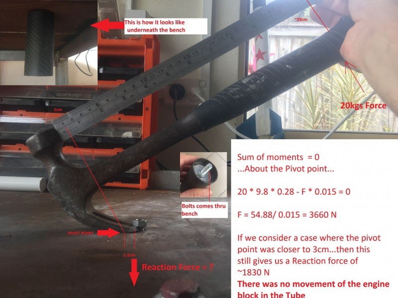
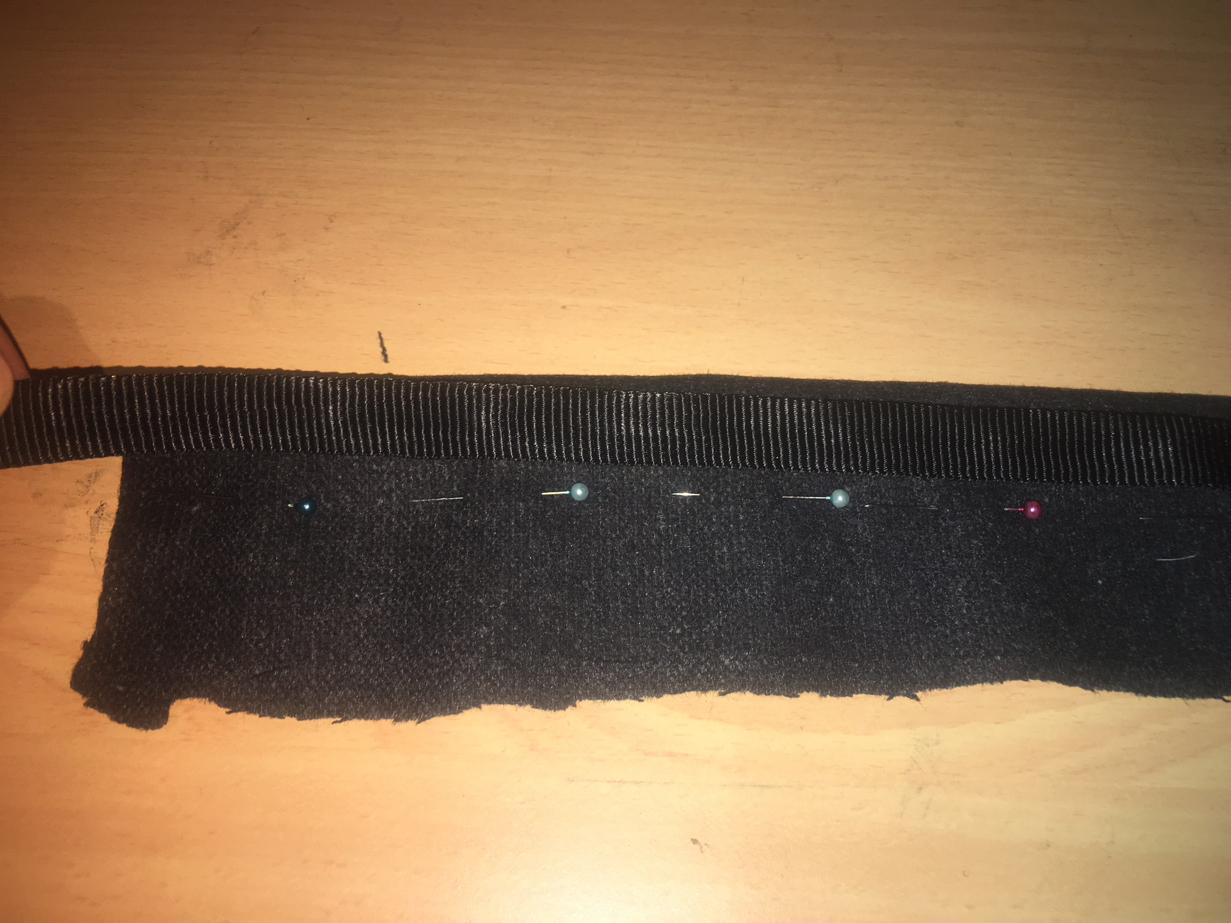
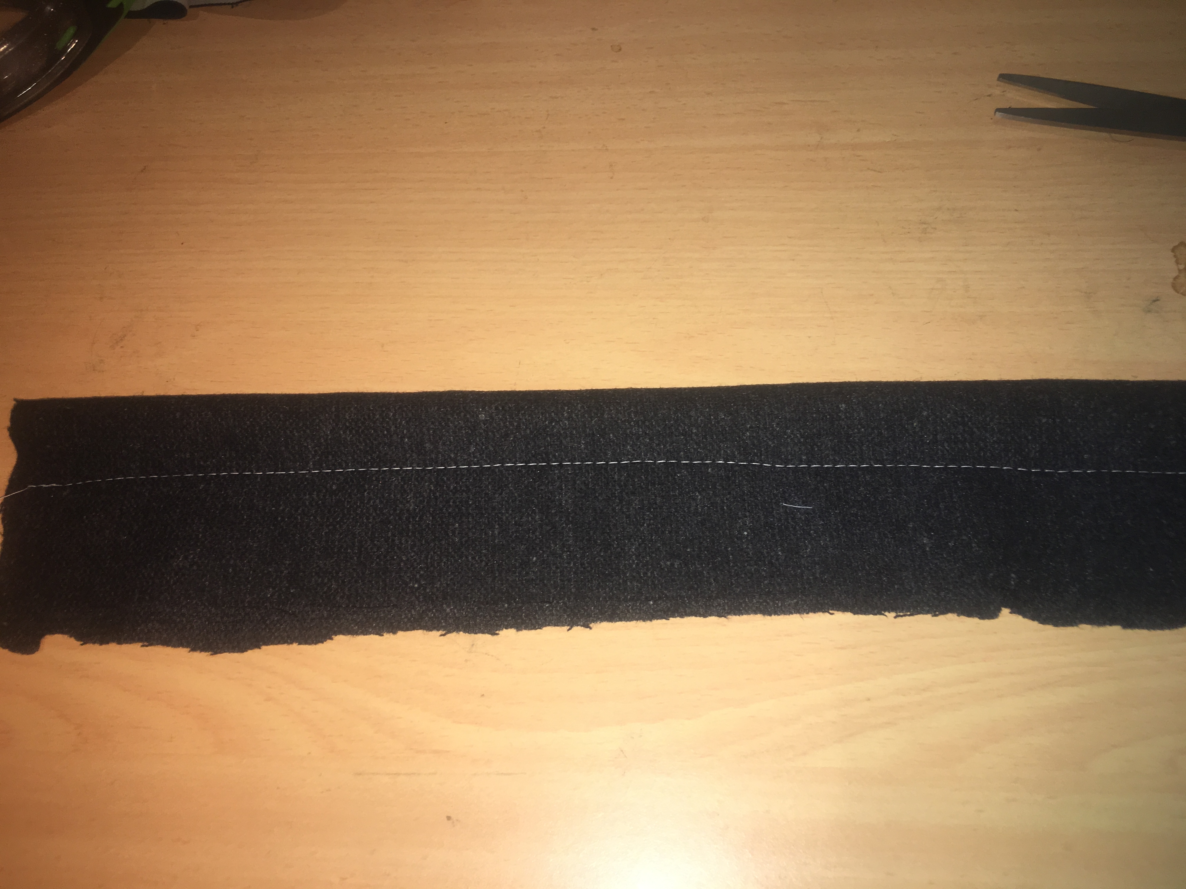
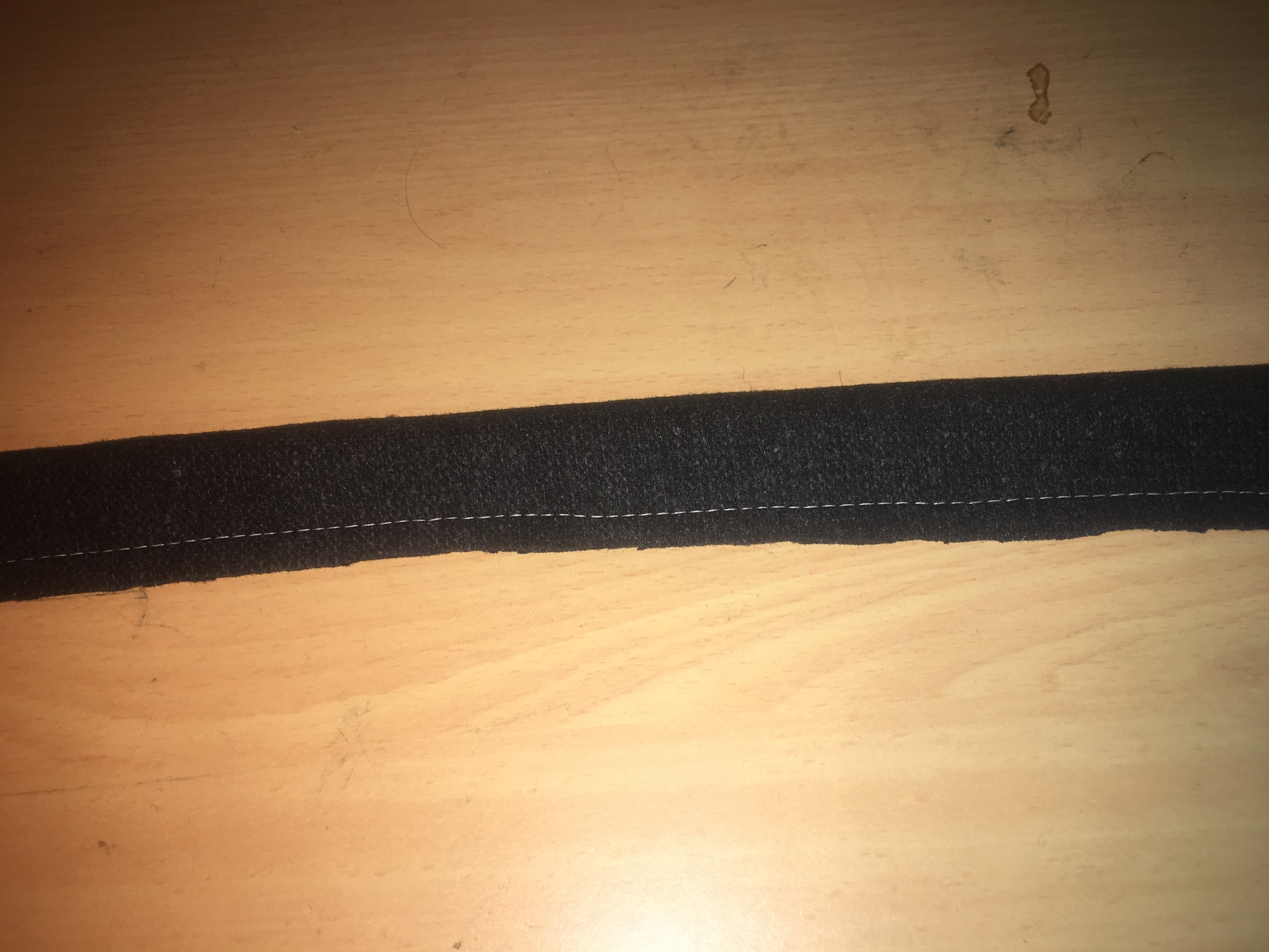
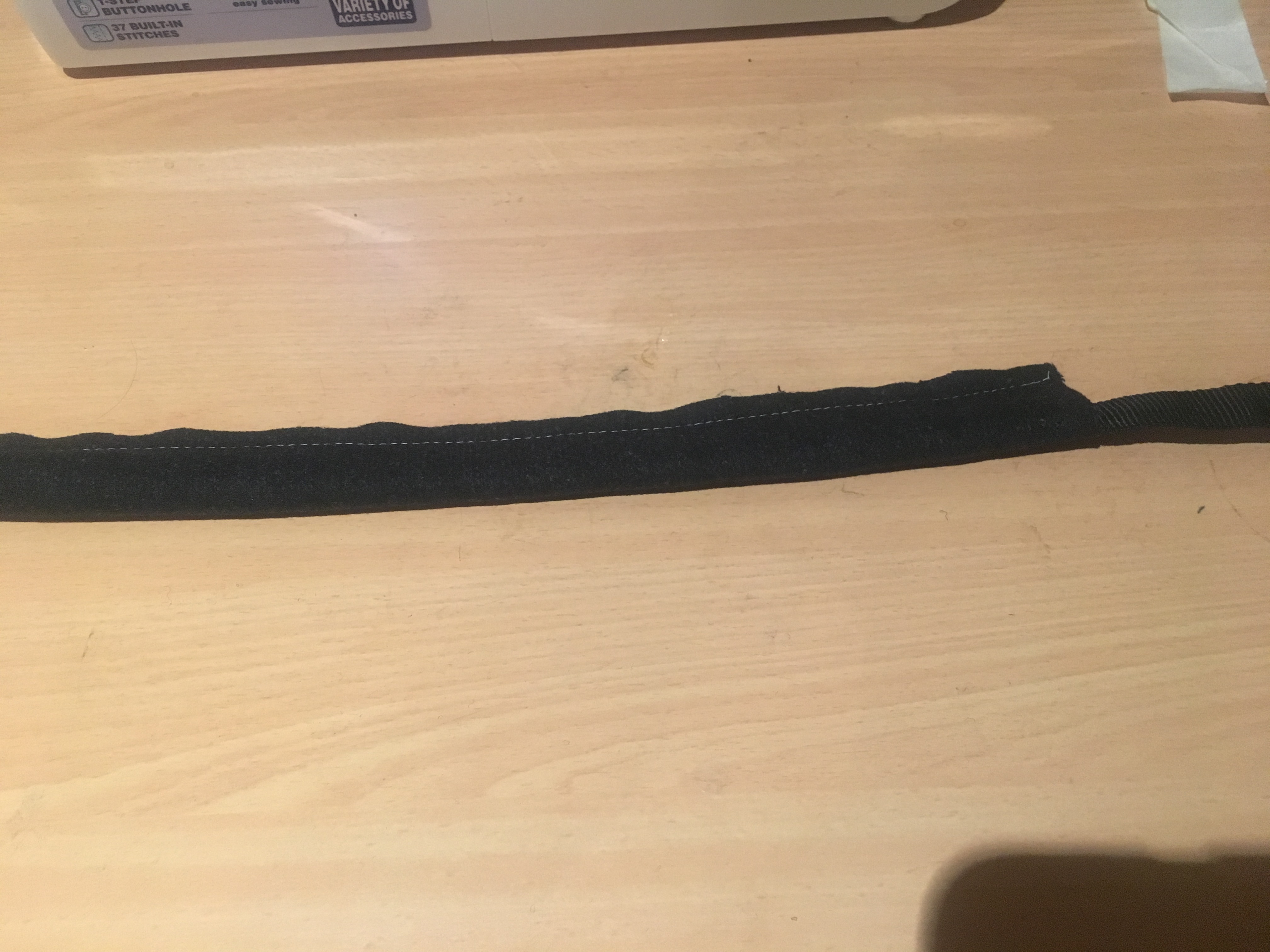
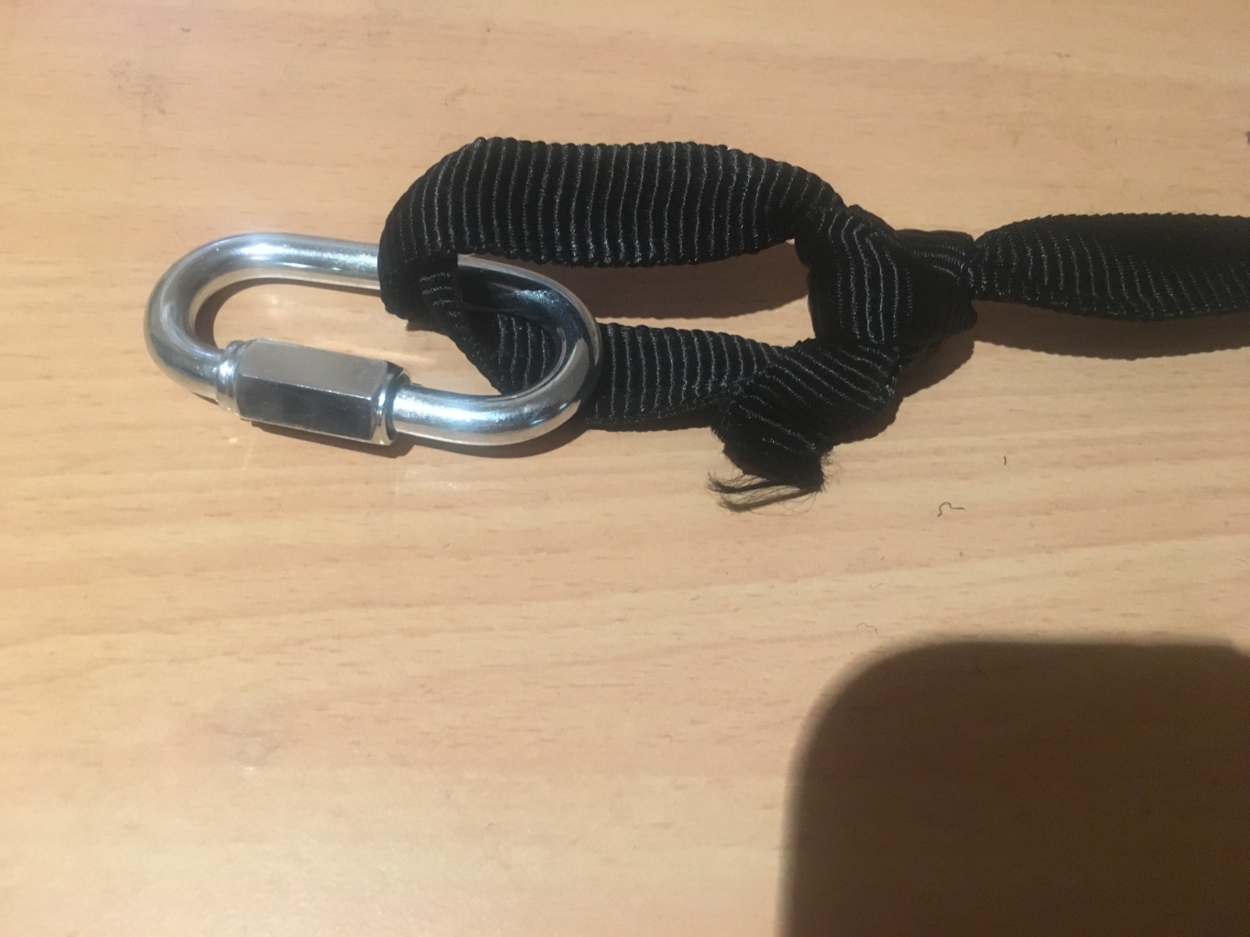
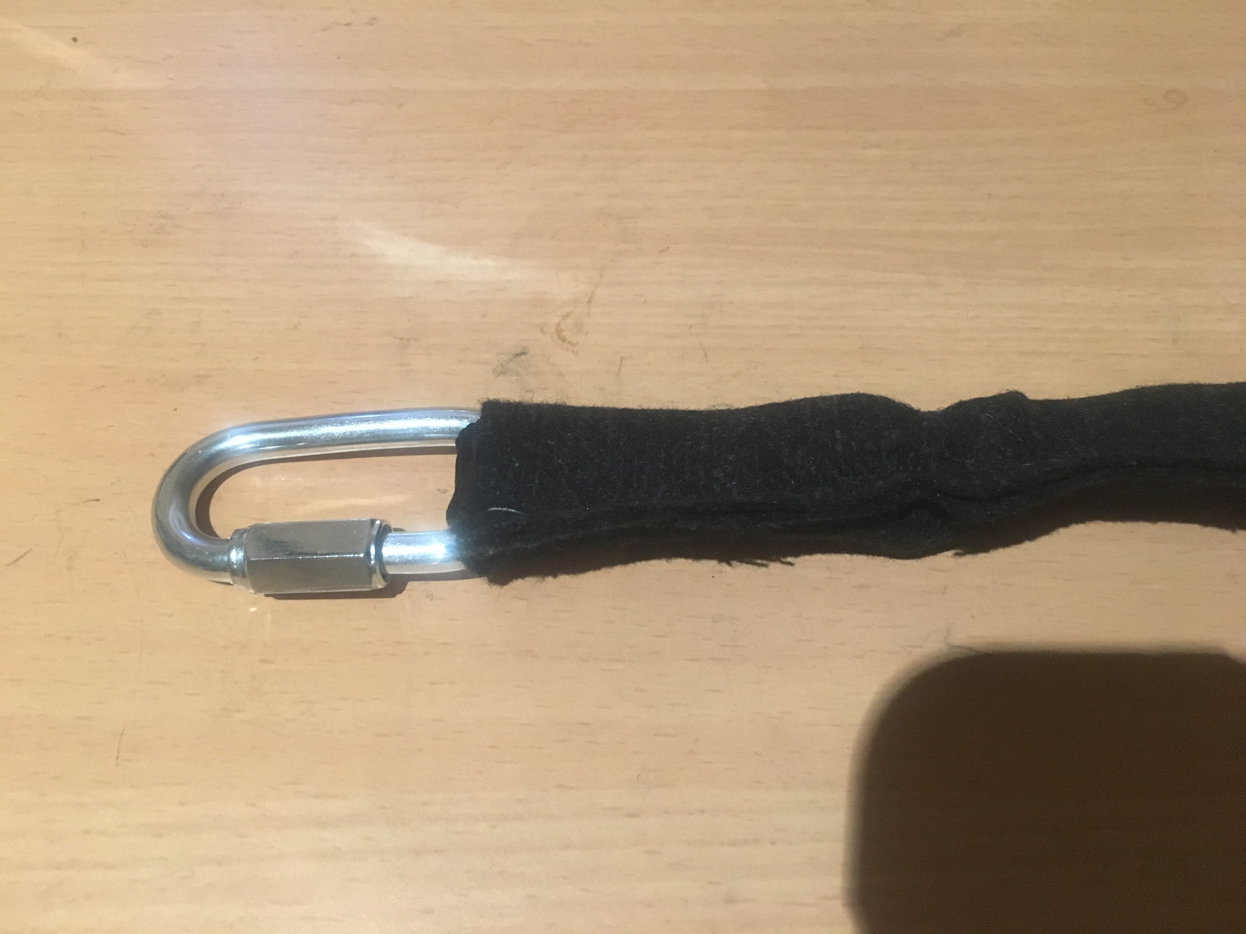
Shock Cord

Many people suggest Tubular Nylon. It is extremely strong. AusRocketry says 9/16 version of this machines has a max tensile strength of 2000lb (that is lb, not lbf). Another site with same size material has a strength of 1500 lb. So not sure why there is a discrepancy, but perhaps I should question the AusRocketry value.

Now, let’s consider the situation where we have some Black Powder ignite and produce a pressurized chamber. Energy is neither destroyed or created, so we need to account for it. Energy would go into:-

  • Breaking the shear pins
  • Heating/moving air as its bursts the components apart
  • Imparting energy into nose cone
  • Imparting energy into the Avionics Payload

We would expect the Nose Cone and Avonics may to be sent in opposite directions (conversation of momentum) and the Shock-cord to be stretched to its maximum length and then it would produce an equal and opposite force, that keeps the components tethered. This Shockcord is effectively like a spring – and like a spring it stretches and absorbs energy. We can work out what forces are in the ShockCord based on the energy it absorbs.

F = \sqrt {2kE}.

k = Spring Constant

E = total energy

F = force that the Shock-Cord is experiencing.

If the force (F) is excessively large (exceeds the rated strength of the Shock-Cord), then we have  a problem.

So how much Energy is being absorbed?

The Black Powder produces a pressure and we know the volume of the tube. We assume that the Blackpowder ignites completely and the production of all these gases occur before any venting can occur. All ideal (and unlikely in the real world) but this gives us a conservative look at it.

Now, E = PV = nRT

P = 10psi = 10/14.7* 101325 ~ 69,000 Pa

V = 0.049 * 0.049 * 3.1415 * 0.41 = 0.0031m^3

E = 69,000 x 0.0031 = 213 Joules

This is a fair amount of energy.

If k = 30,000 (and this is a BIG GUESS)

F = sqrt (2 * 30,000 * 213) ~ 3600 N = 367 kg = 807 pounds

This is well short of 1500 lb or 2000 lb (AusRocketry).

Of course this all hinges on choice of k and I’m not sure if this is a good value.