
I have recently received the PCB sensor board from the supplier and have started soldering components. A few pictures of this are shown below.
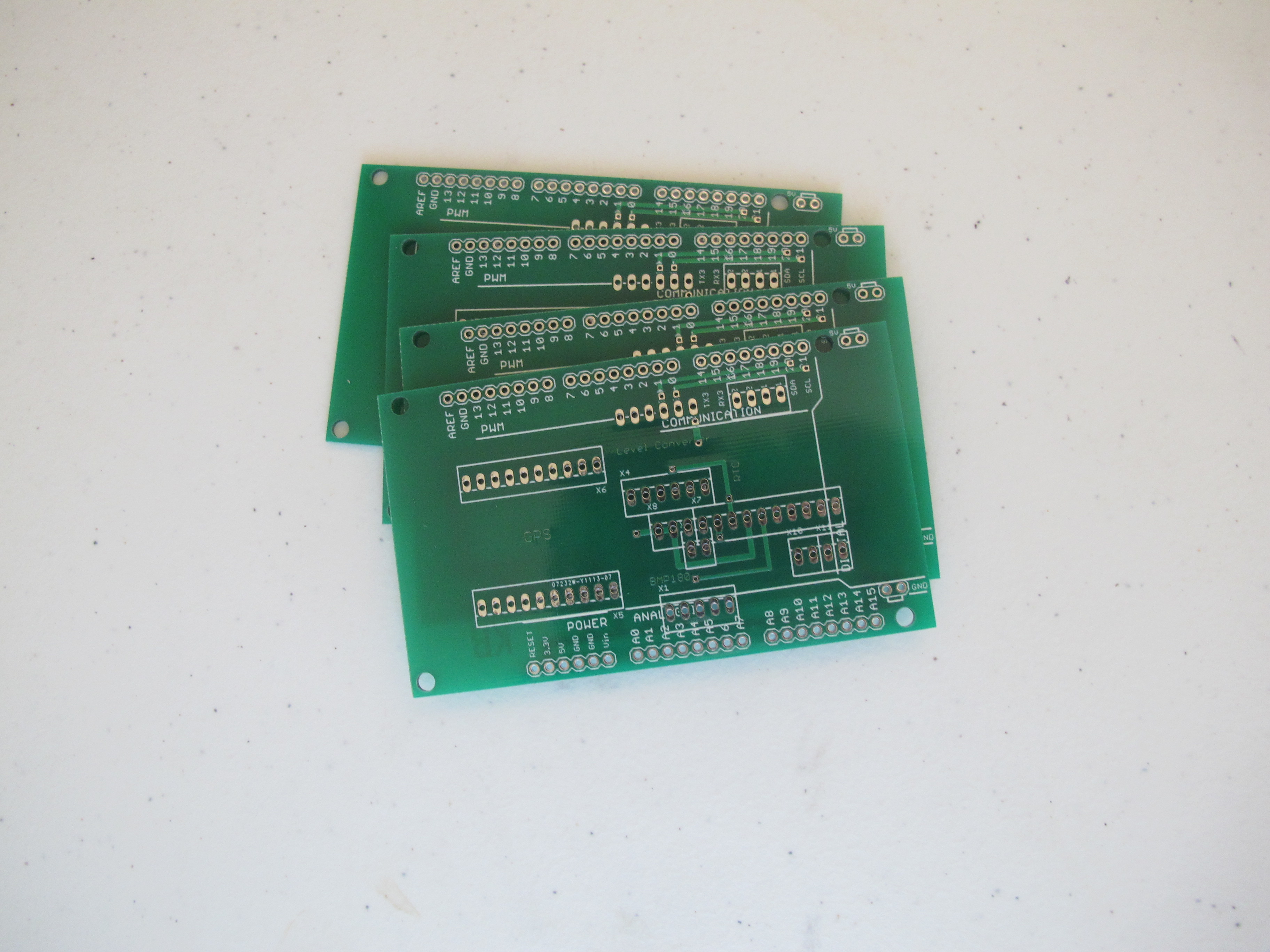
Five boards were received in total. (These are “prototype” boards and the minimum order quantity is five). As you can see, the quality of these is exceptional….much better than anything I could do at home.
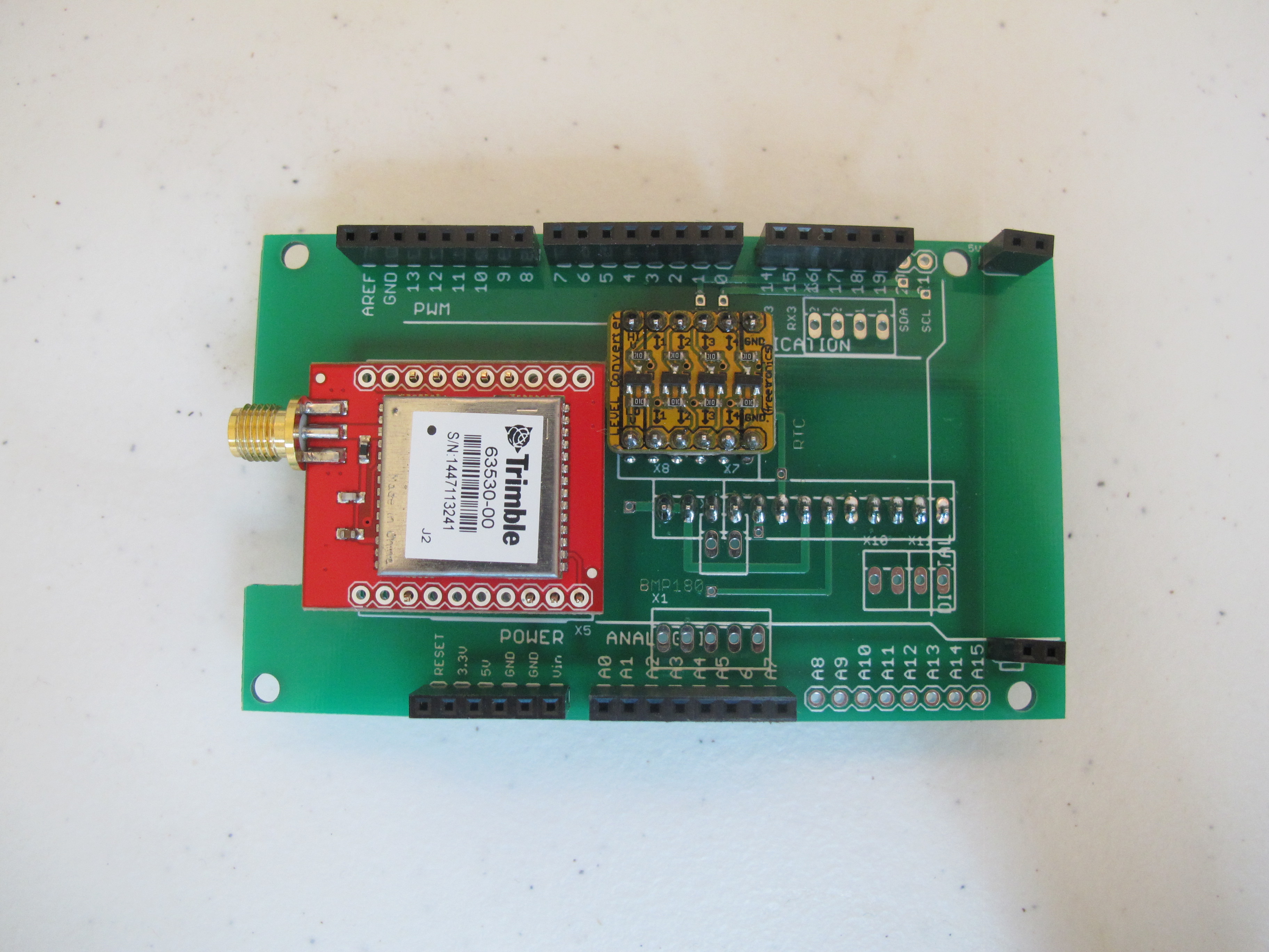
Above is the GPS module (capable of operation up to 50km) and a Level converter. The Level converter is used by the GPS module and the IMU module. These two modules use 3.3 volts. The Arduino EtherMega operates at 5 volts.
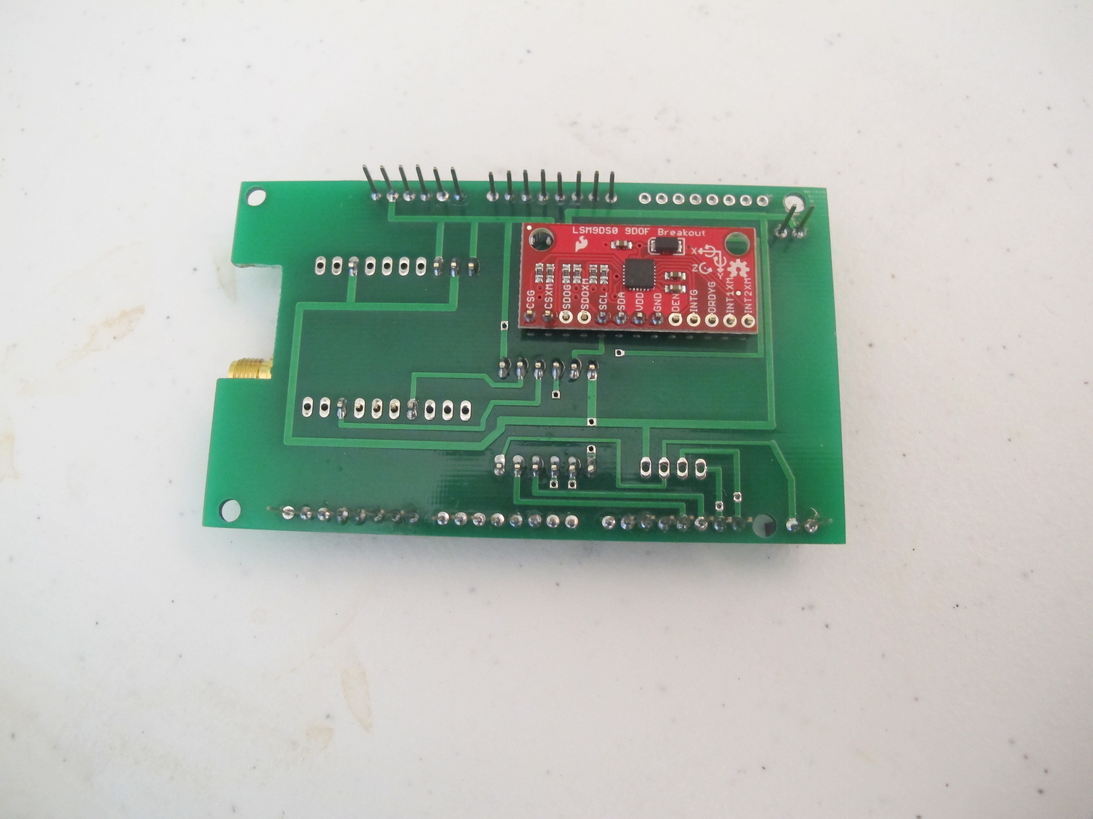
We put this on the bottom for space reasons. This just misses a few pins on the EtherMega by a few mm. So things are tight!
The REAL work beings soon…programming all these sensors. I expect the IMU to be particularly difficult.