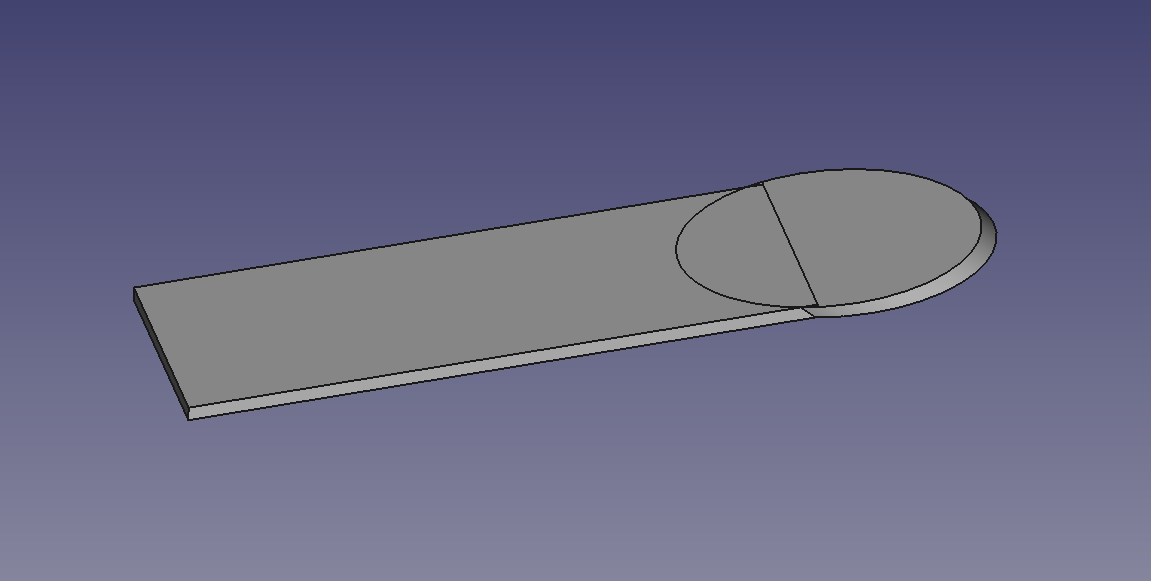
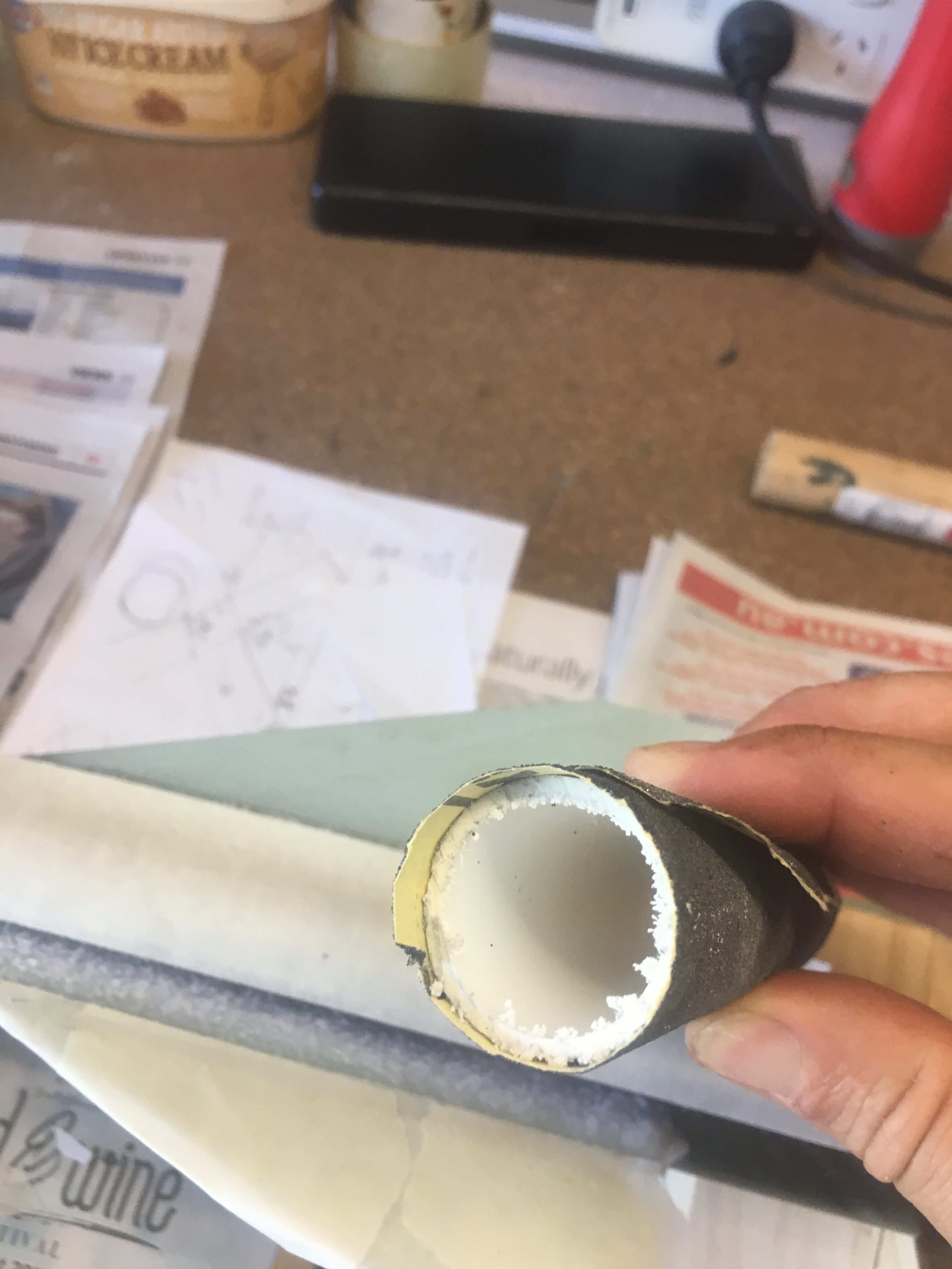
Getting the basic fin cut out
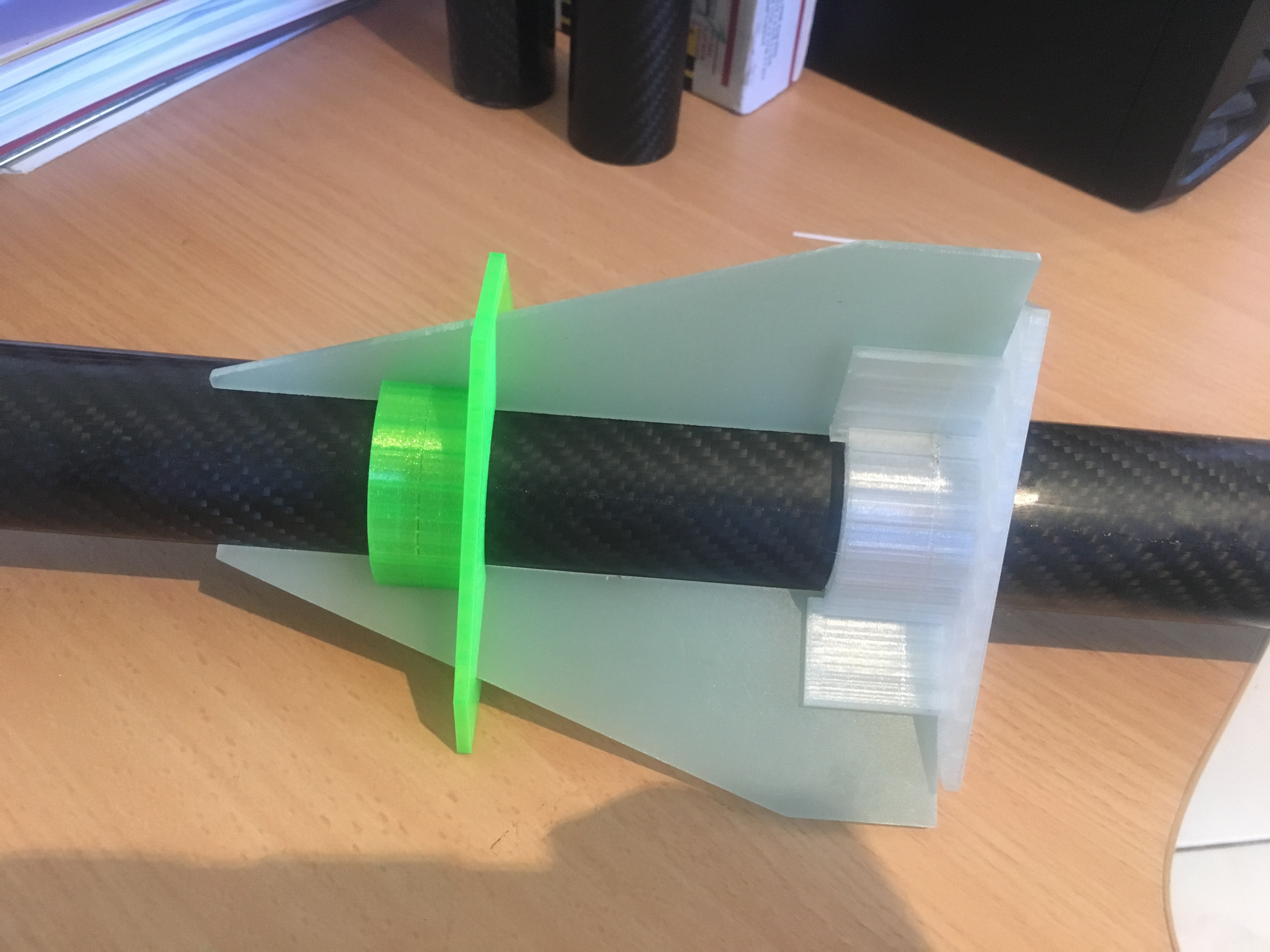
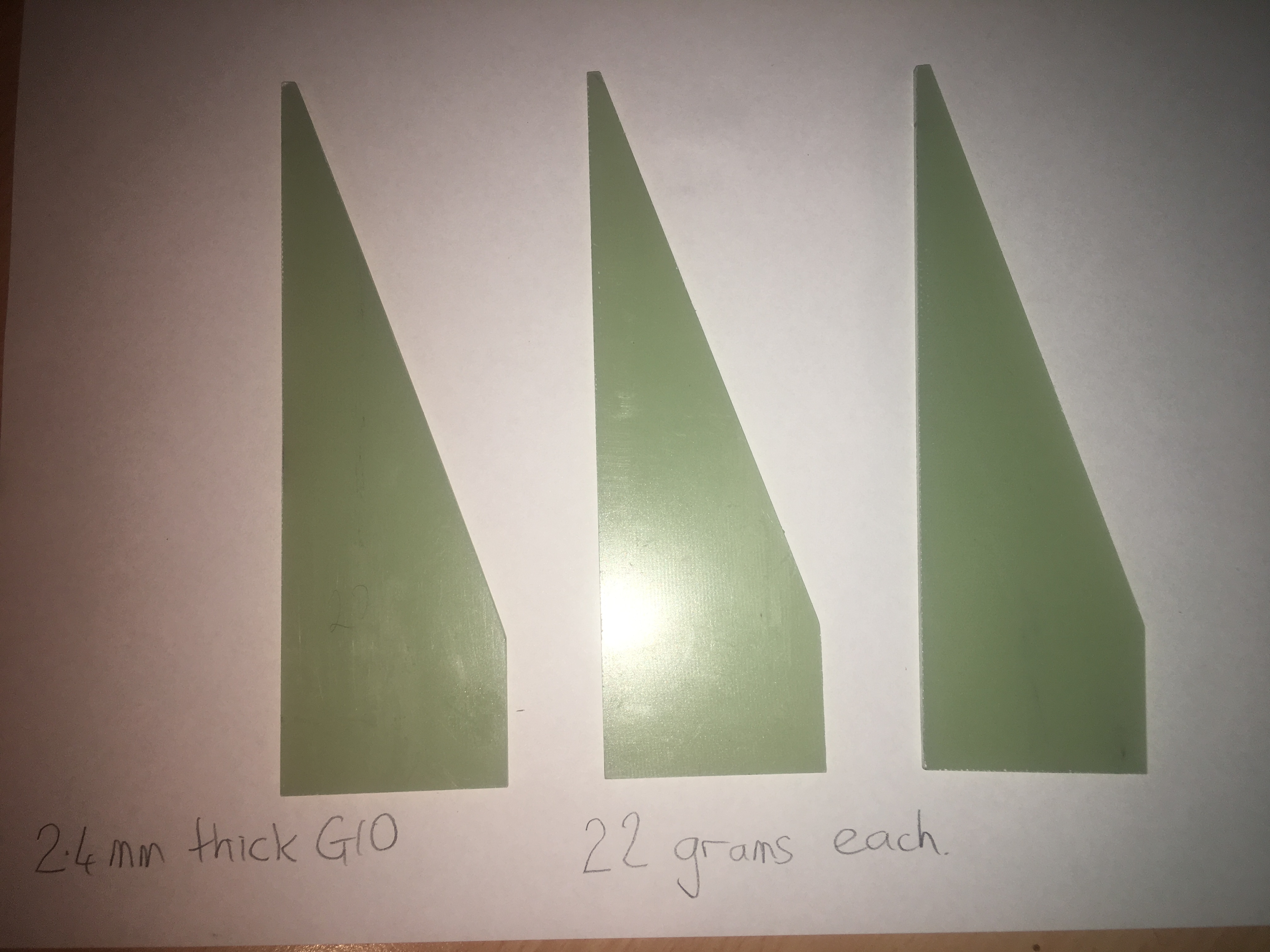
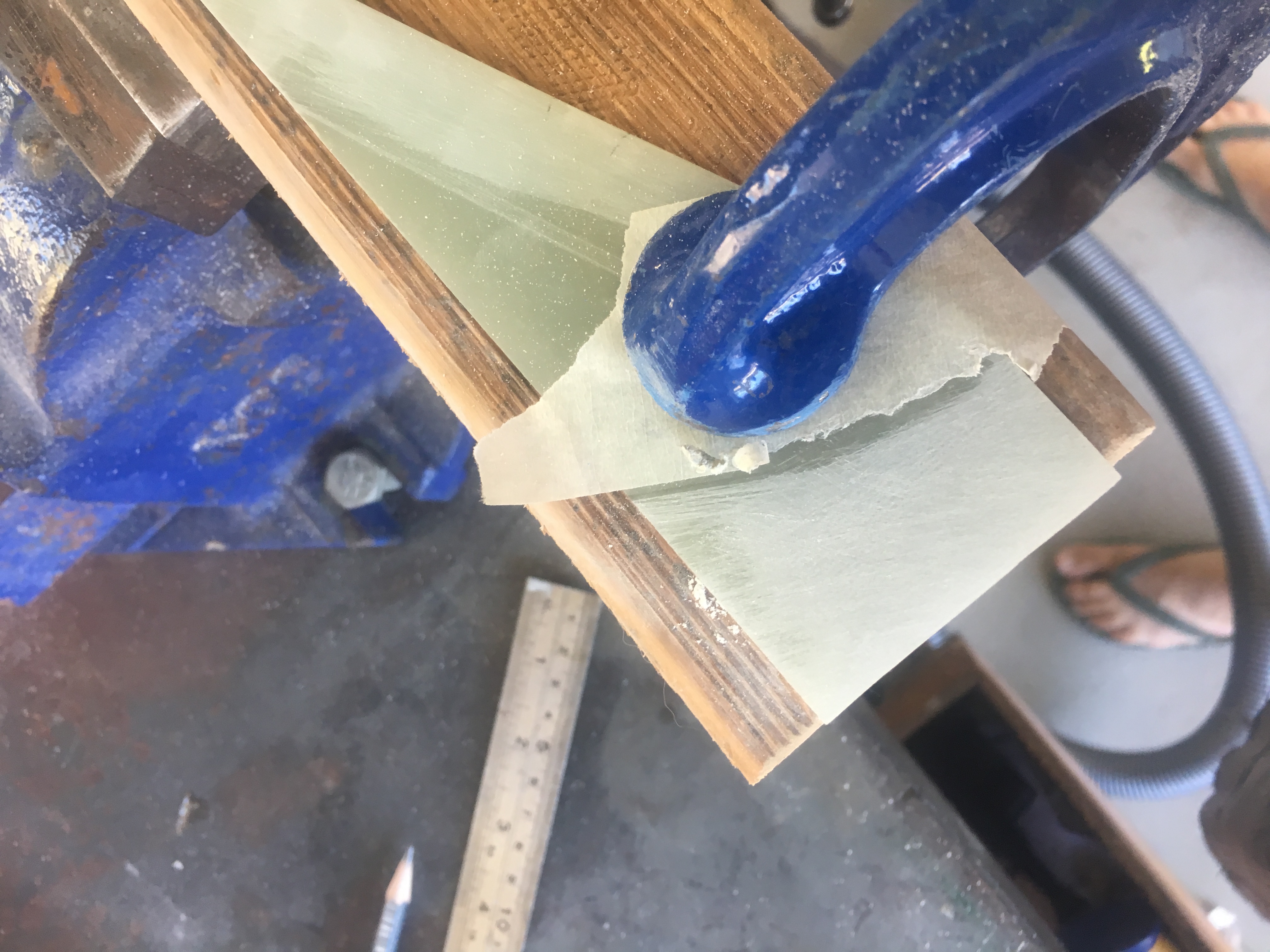
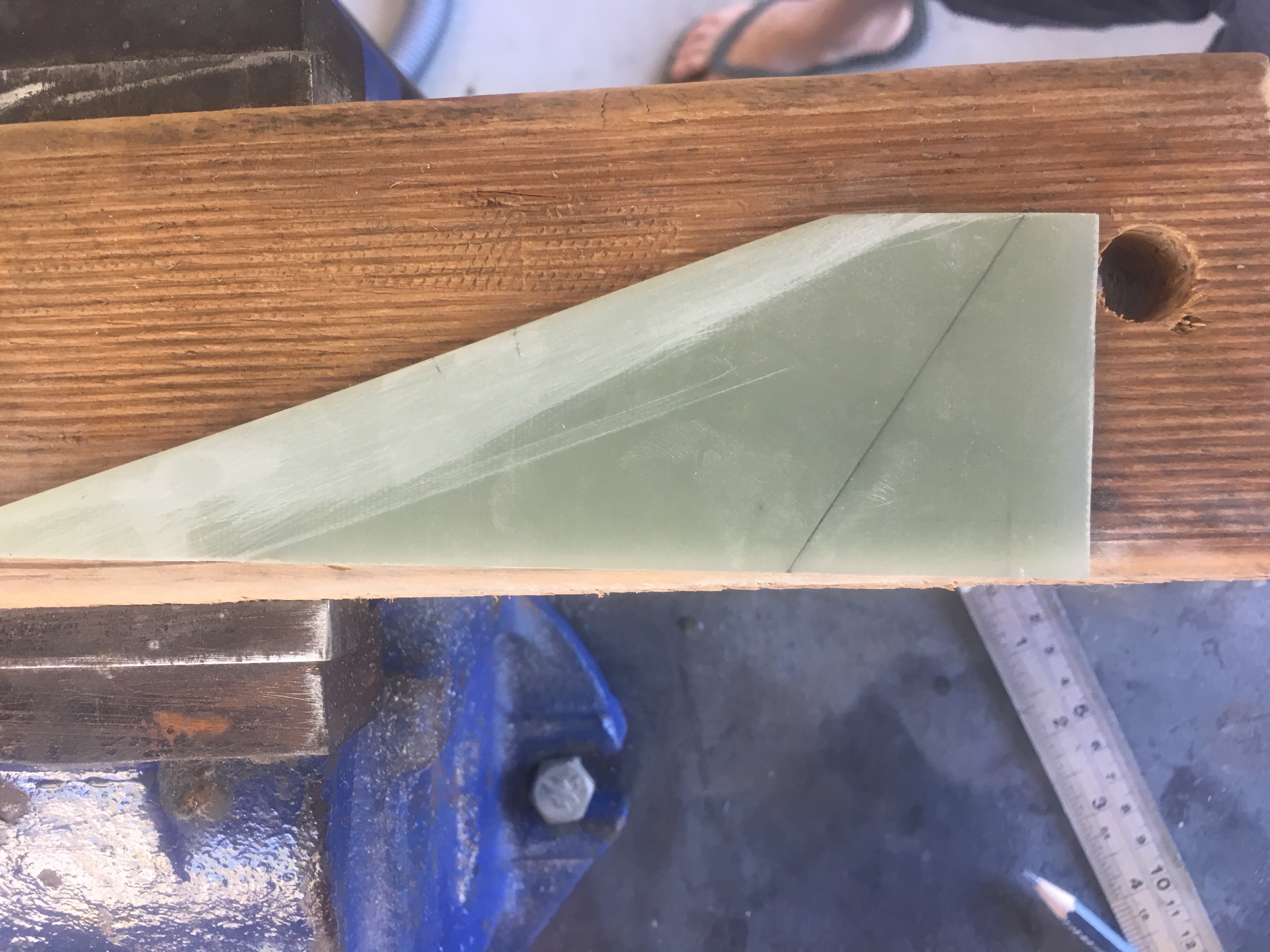
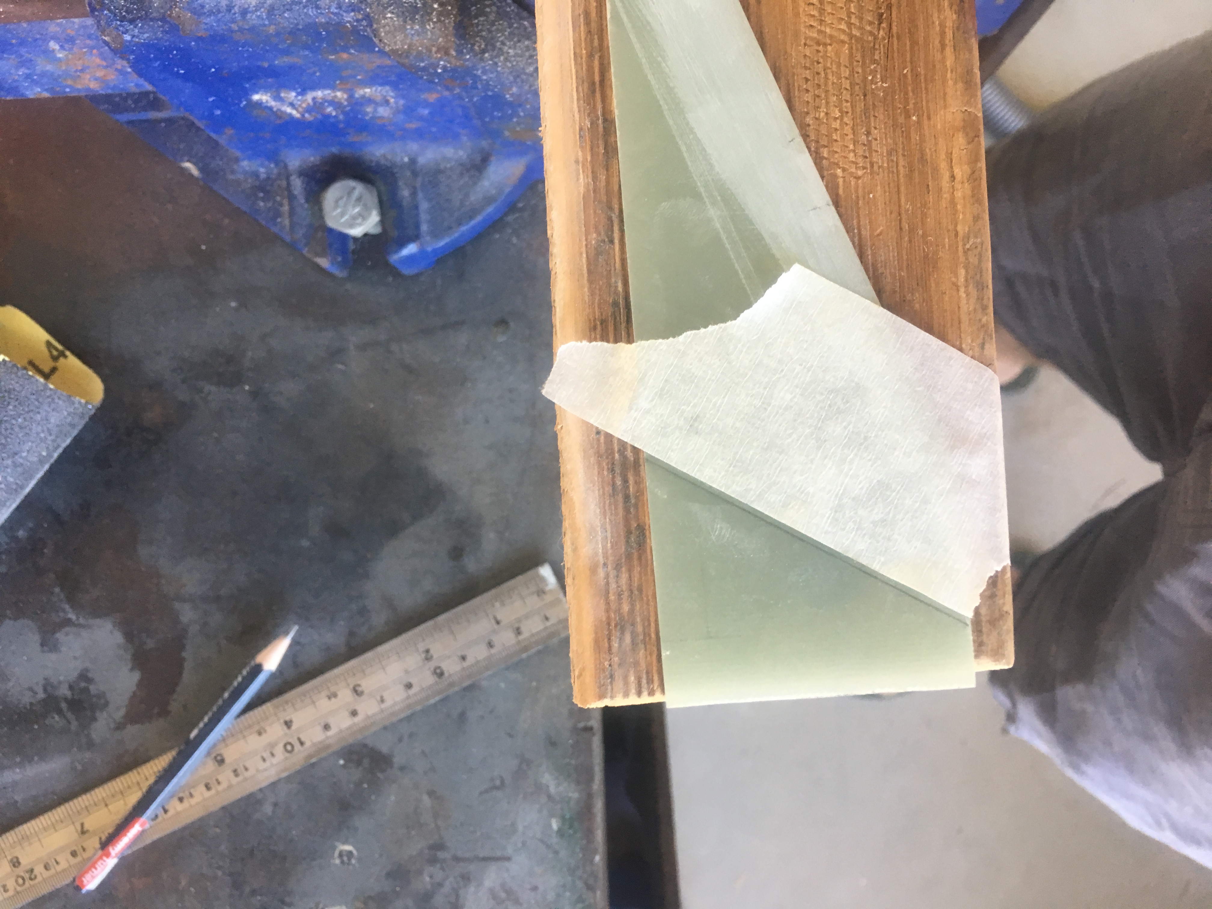
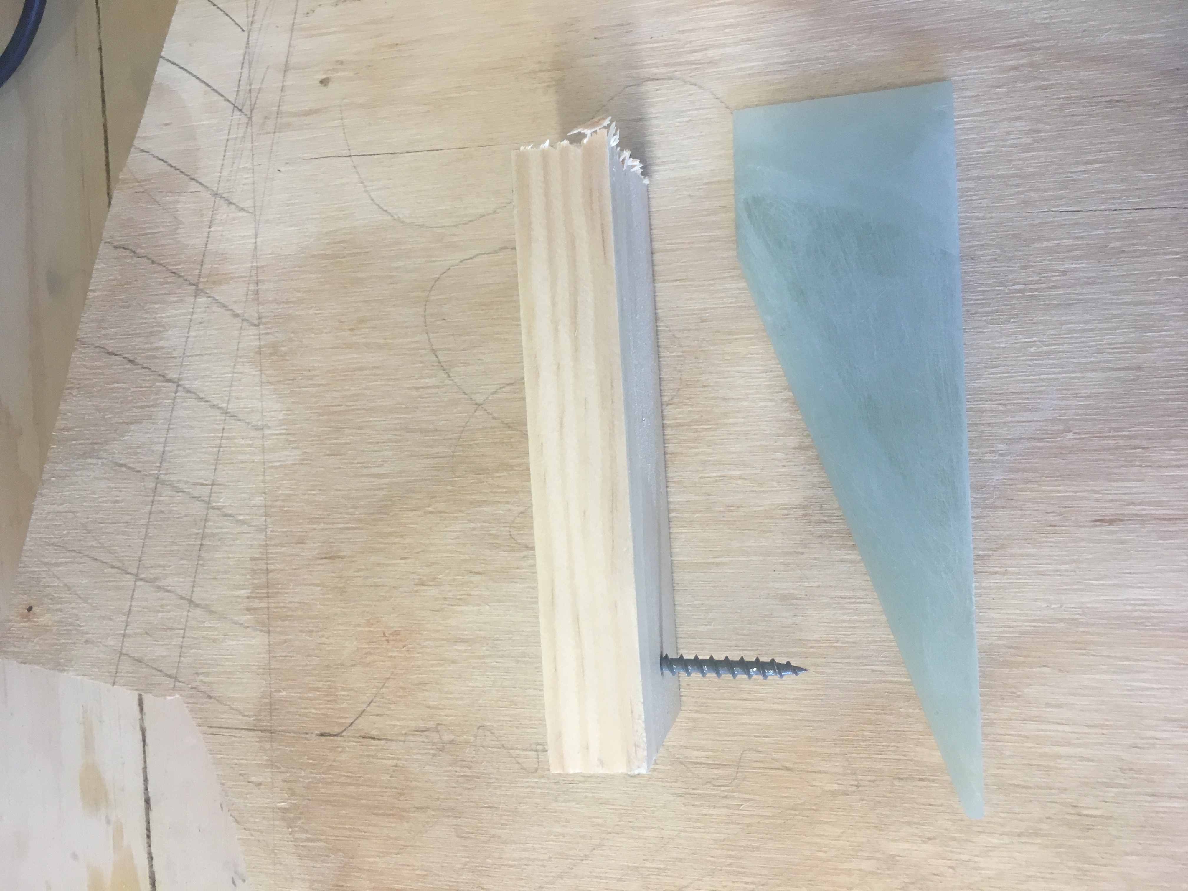
The fins are created from 2.4mm thick G10 plate. I created a clipped delta design and created a jig that I would use to sand the three fins down to the correct IDENTICAL size. Below is a picture of this jig.
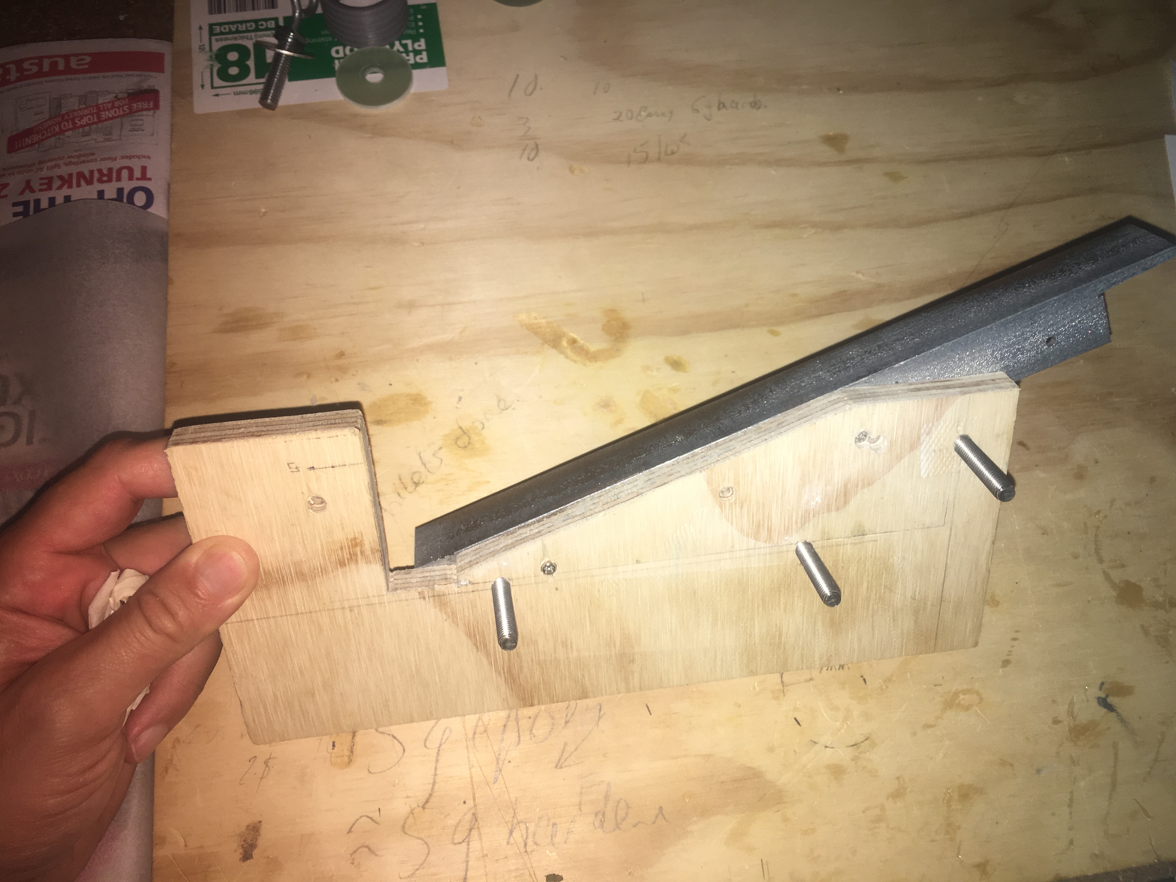
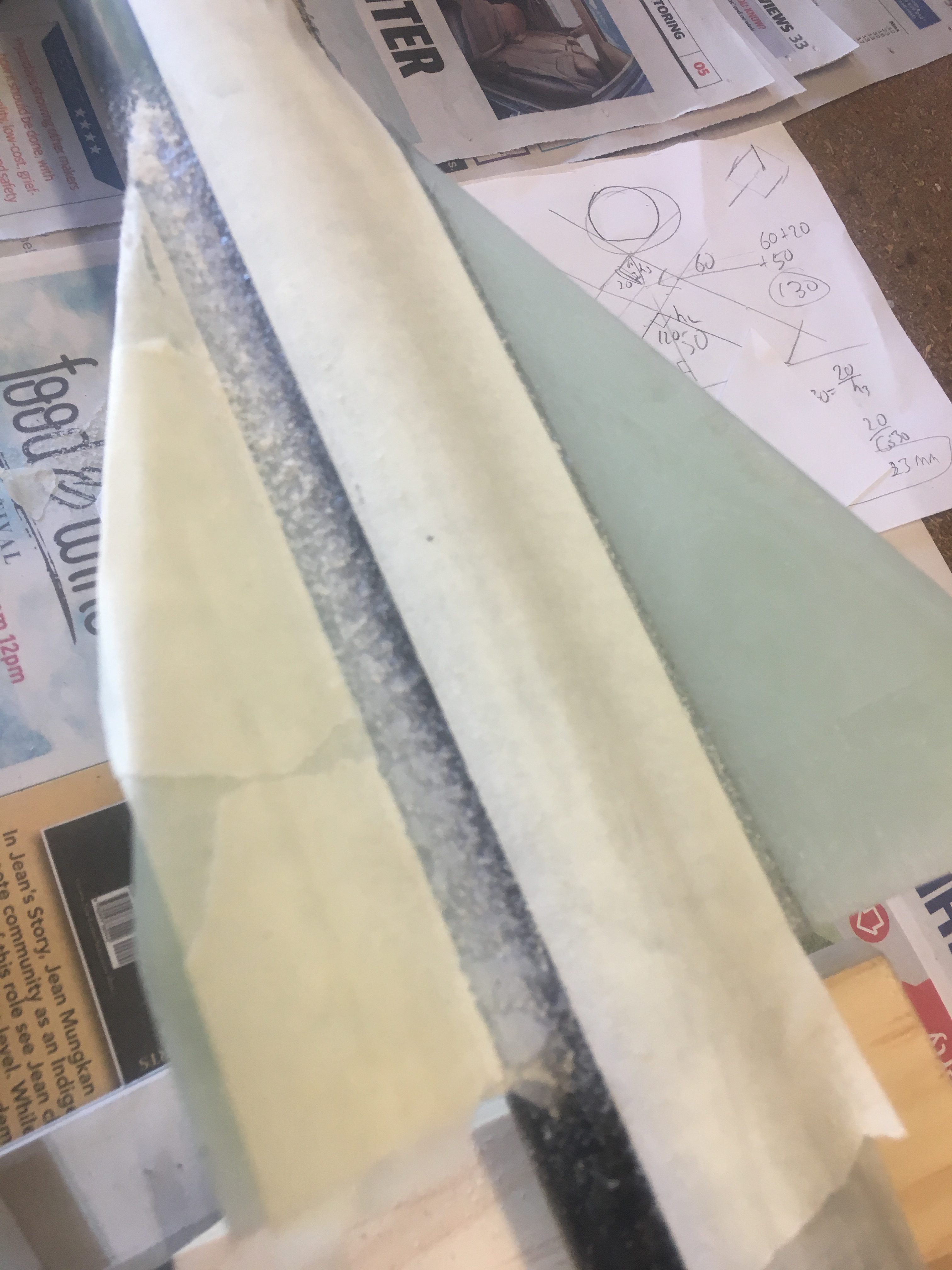
I have used a Steel right-angle bar to sand up against. Here are some pictures of the fins.
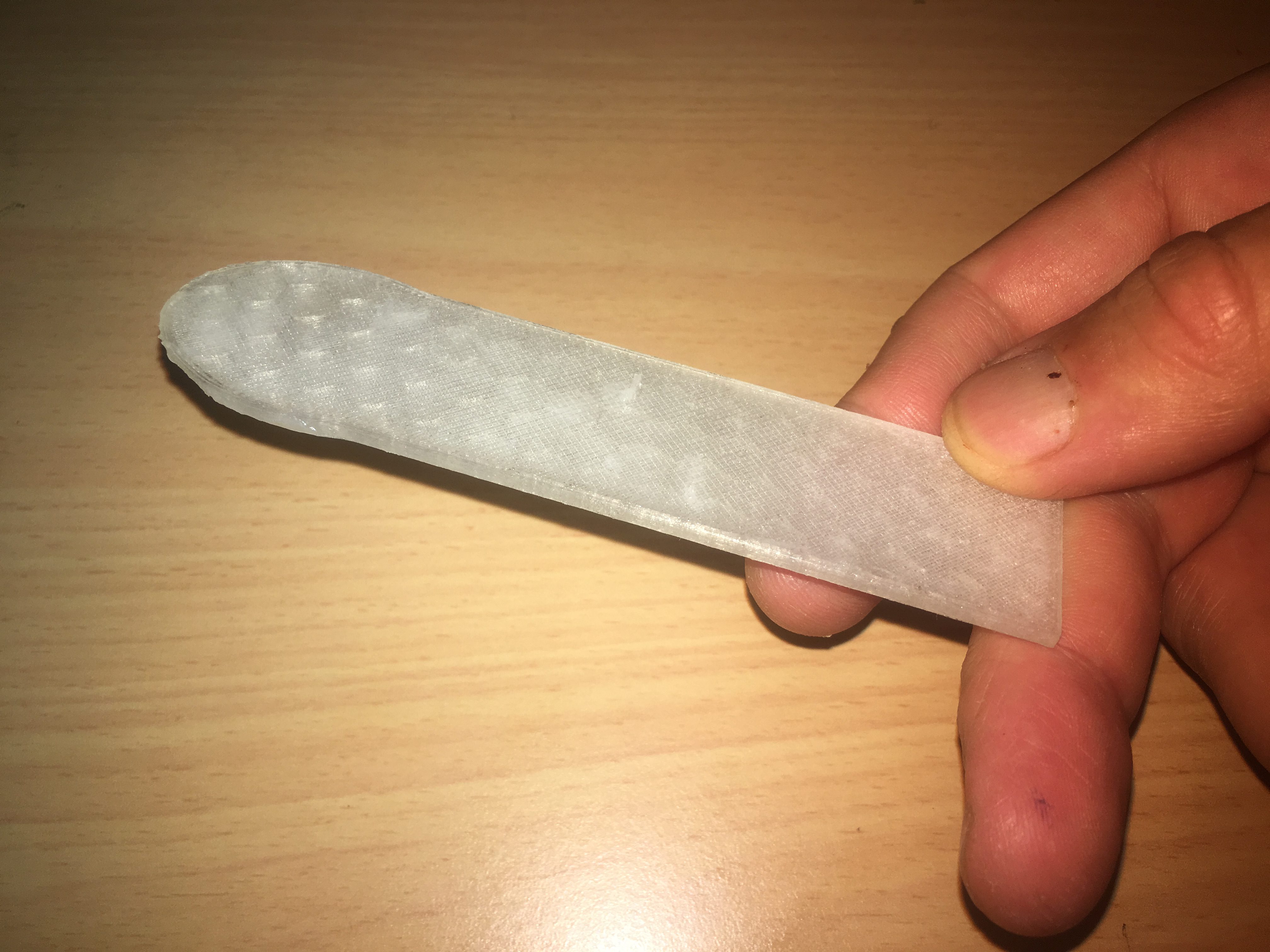
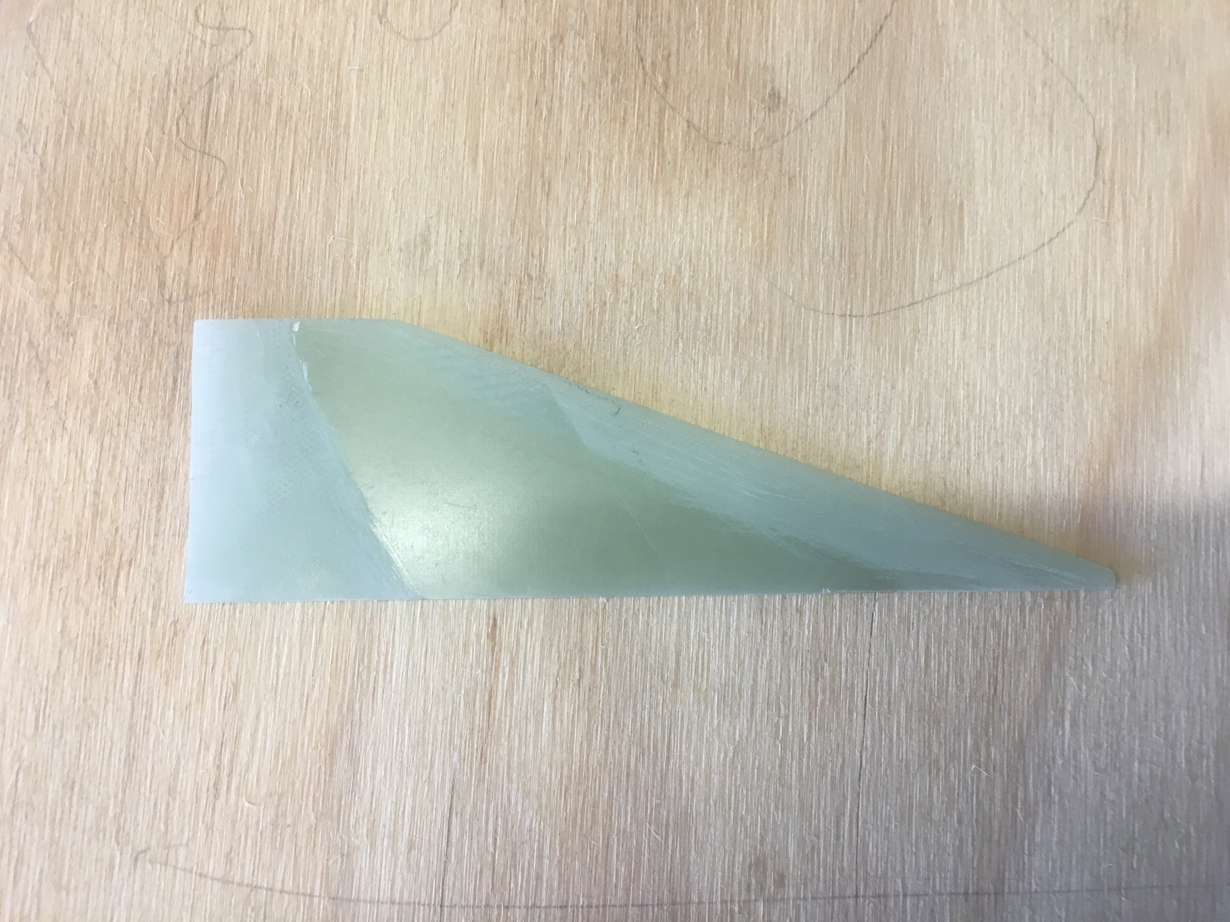
Profiling the fins
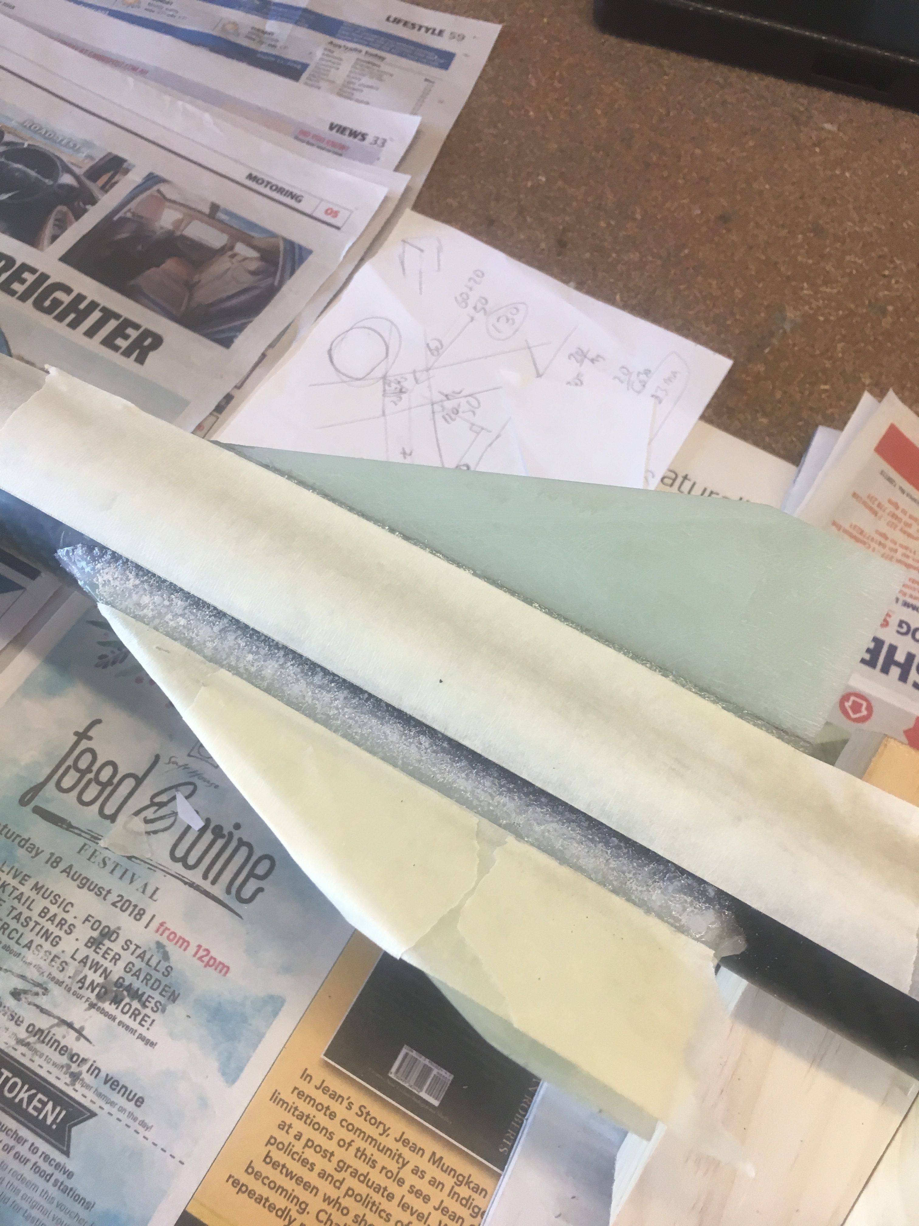
I wanted the fins to have a profile suitable for less than speed of sound. While they will travel greater than speed of sound for some motors, for the majority of the flight they will be travelling below the speed of sound. I also choose this design because it is relatively simple to produce.
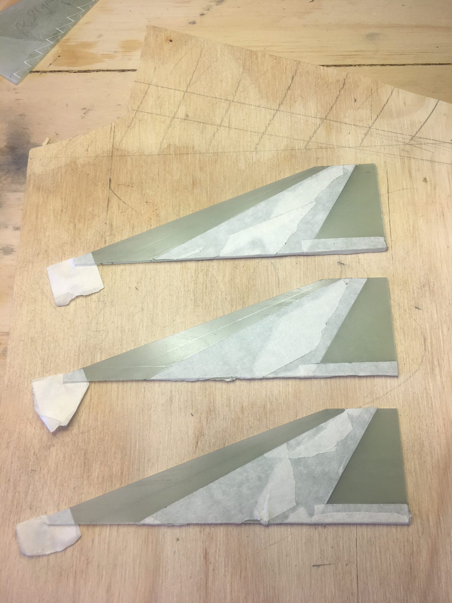
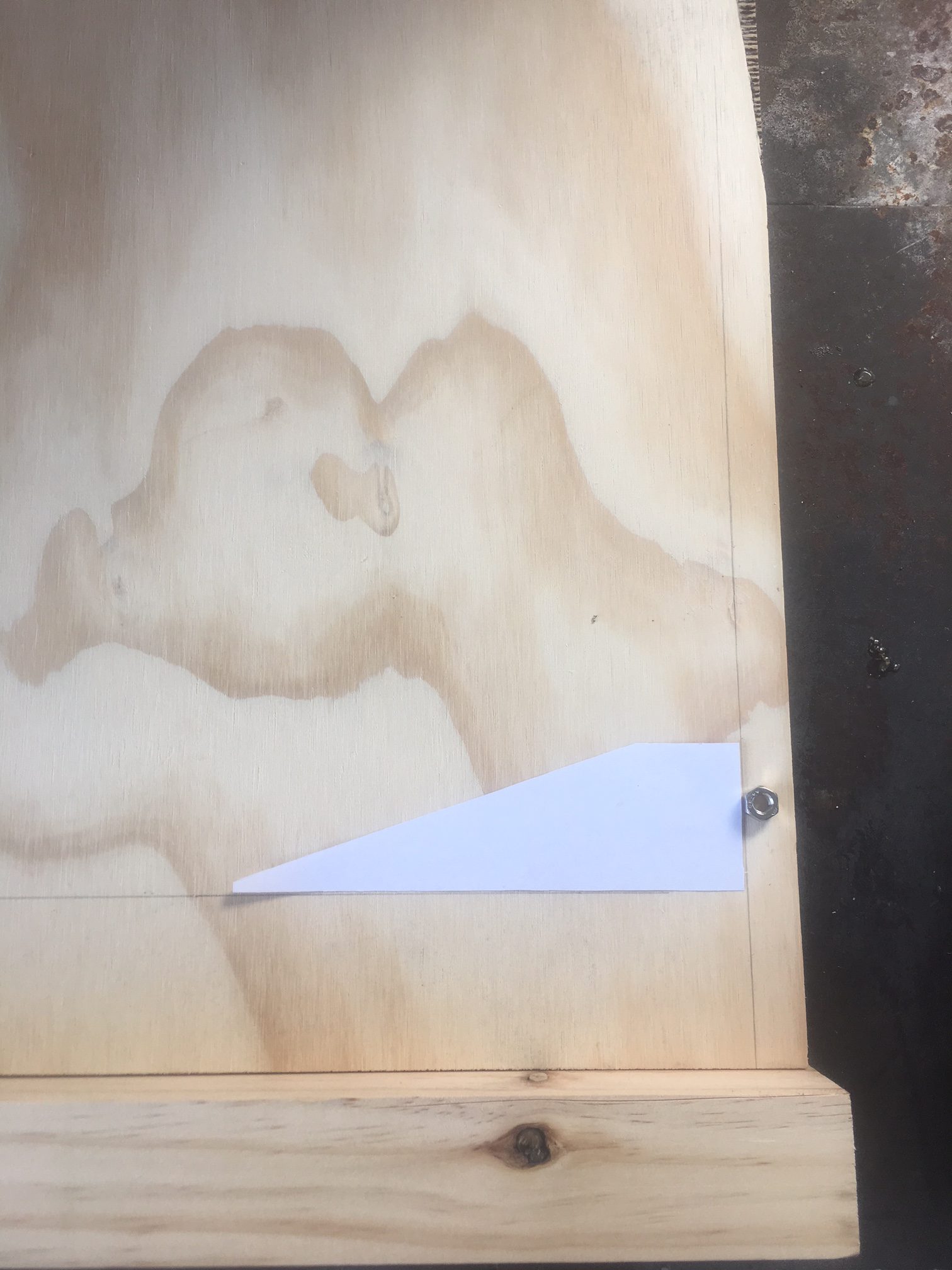
I did all this work by hand. I started by drawing the boundaries of the sanded regions. I even drew a line down the thickness (half way) on leading and trailing edge.
Here are a tonne of photos showing this process.
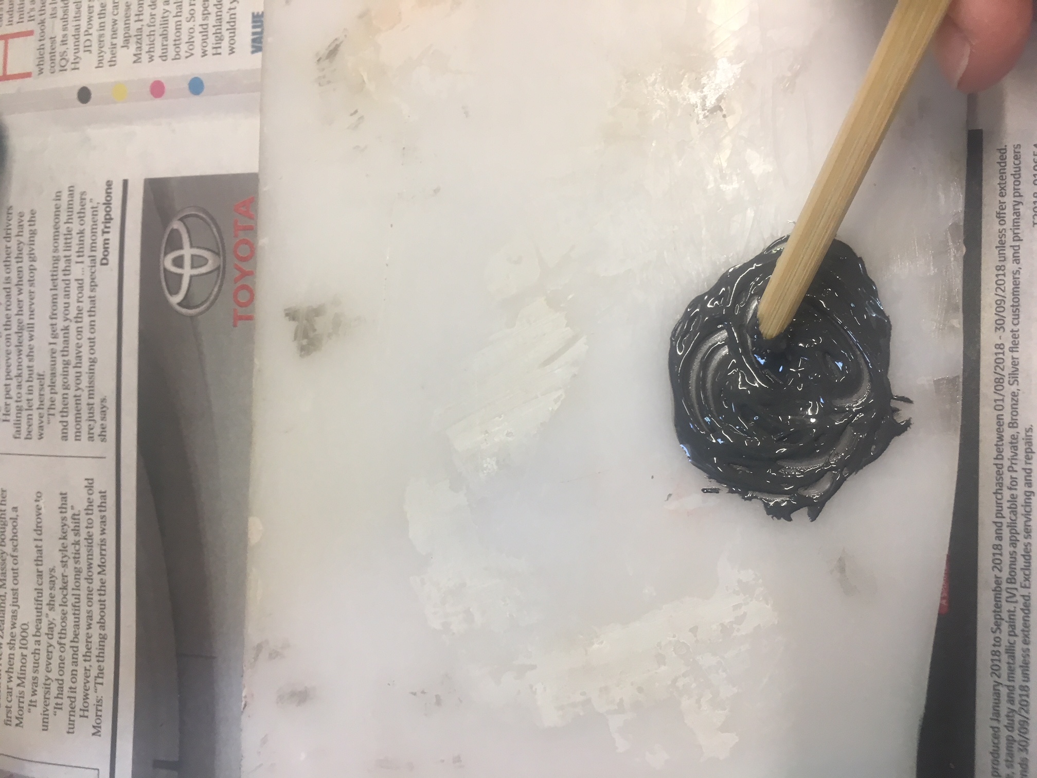
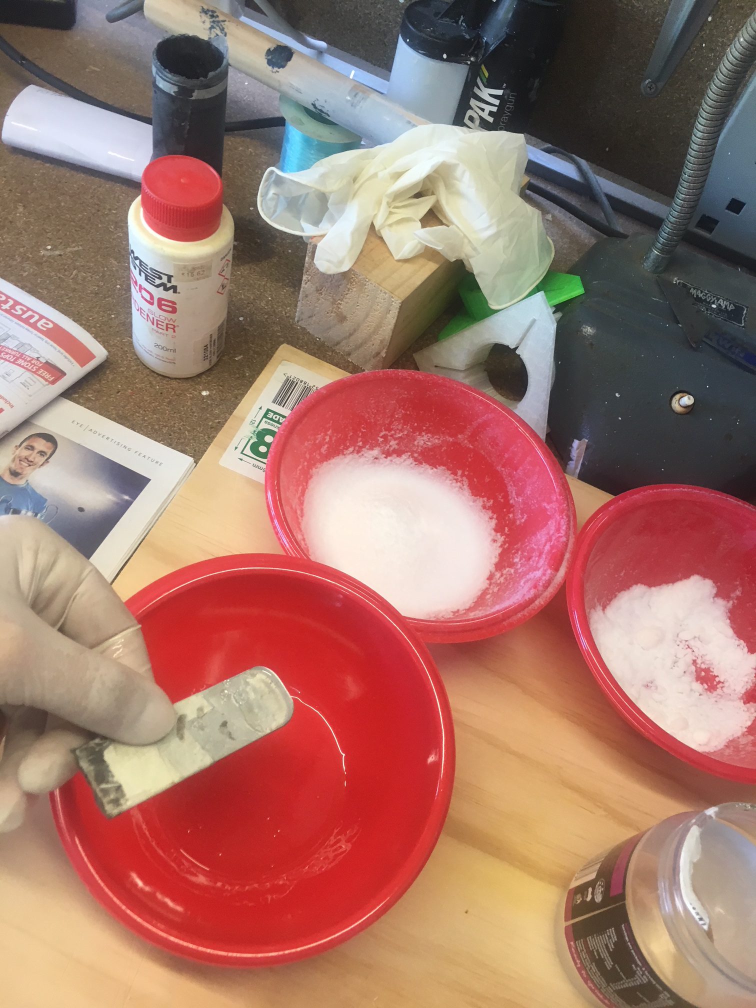
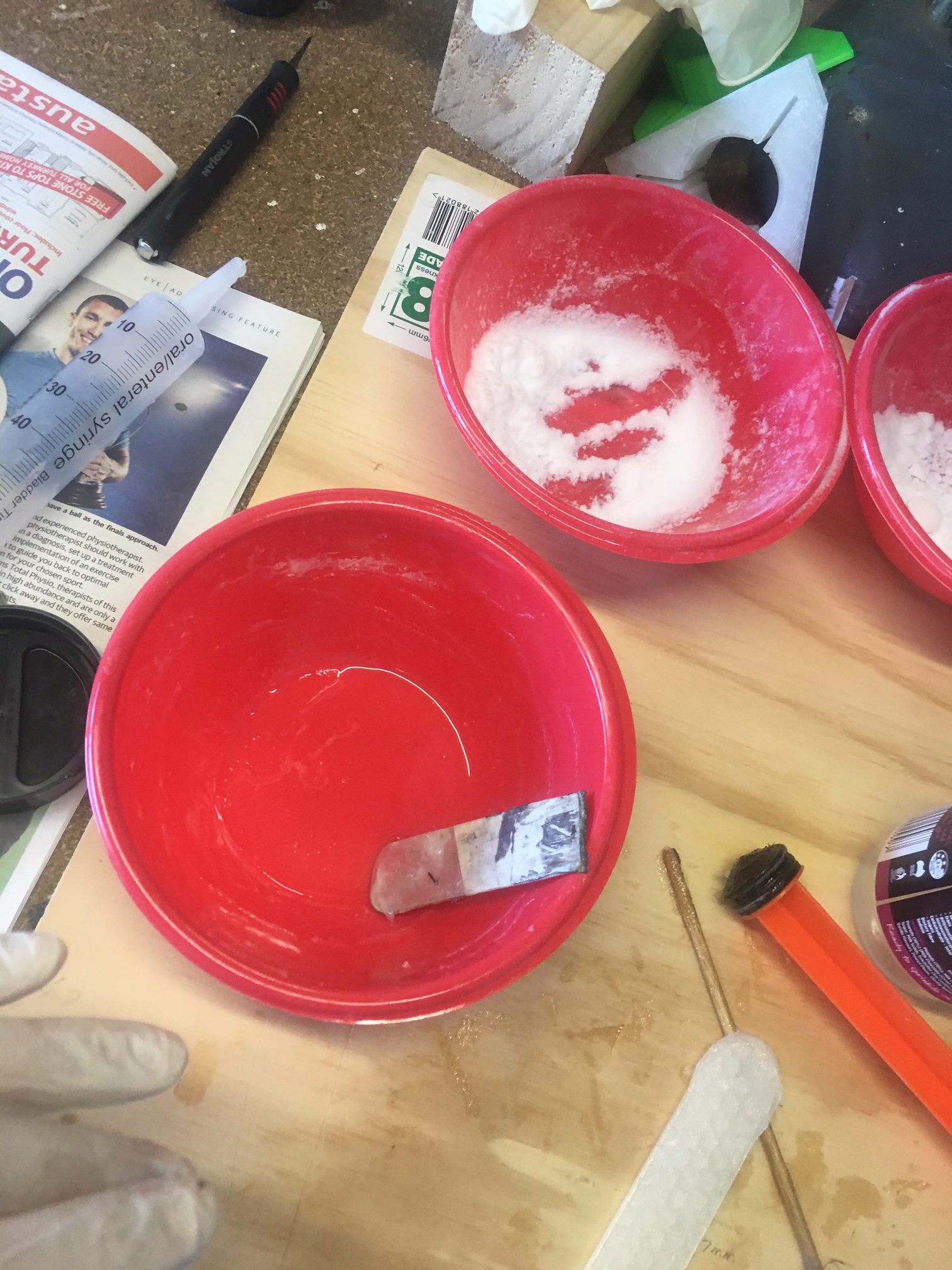
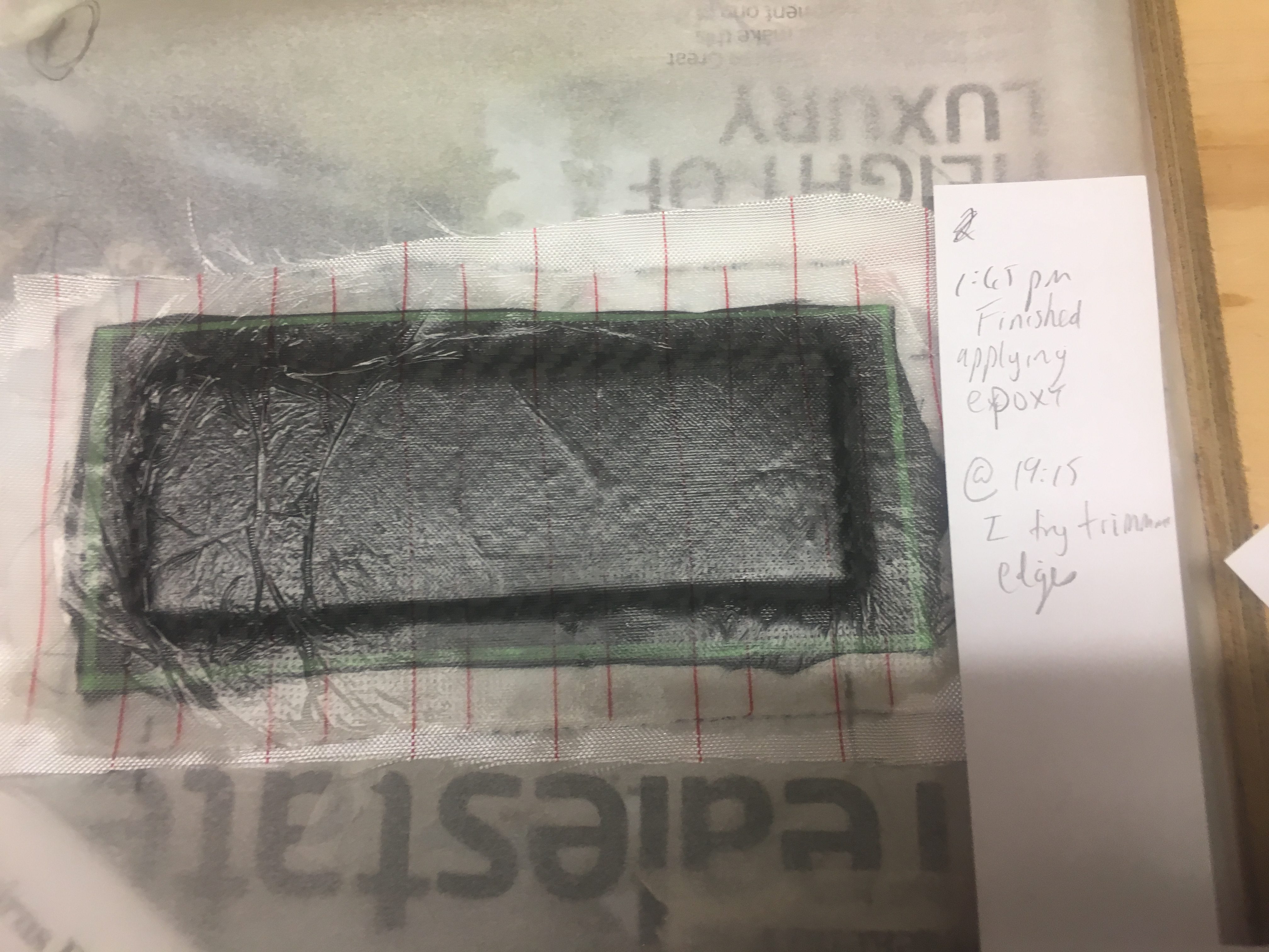
Surface Preparations for Epoxy
It is very important to do all fin preparations BEFORE we attach them to the air-frame; it is a lot easier to do.
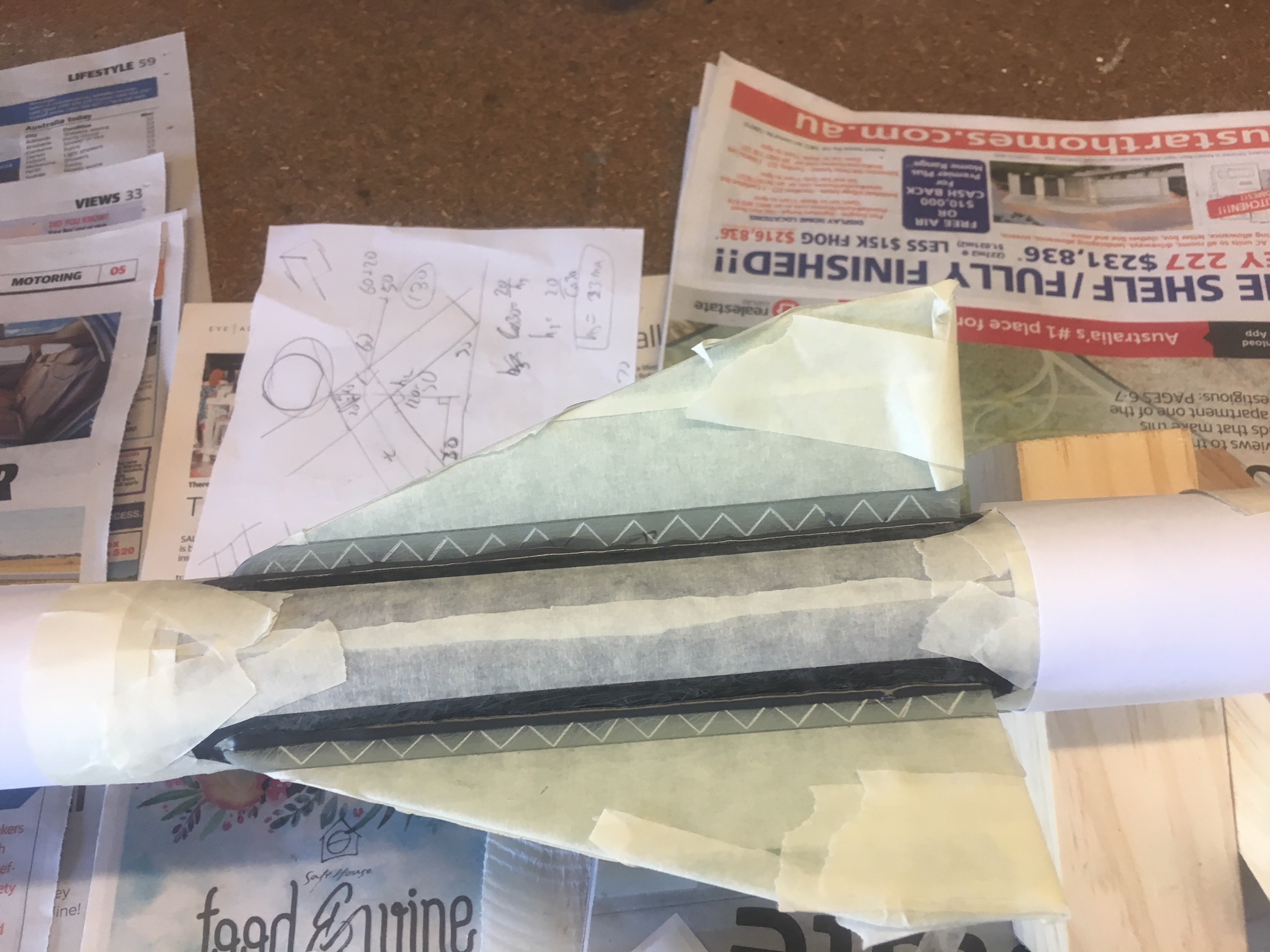
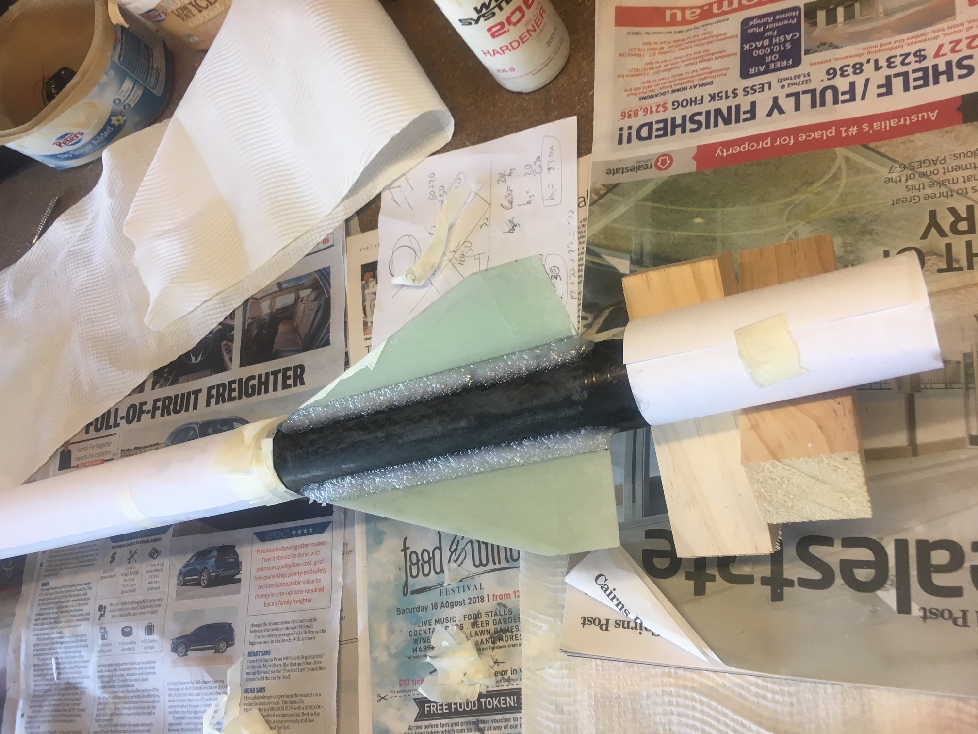
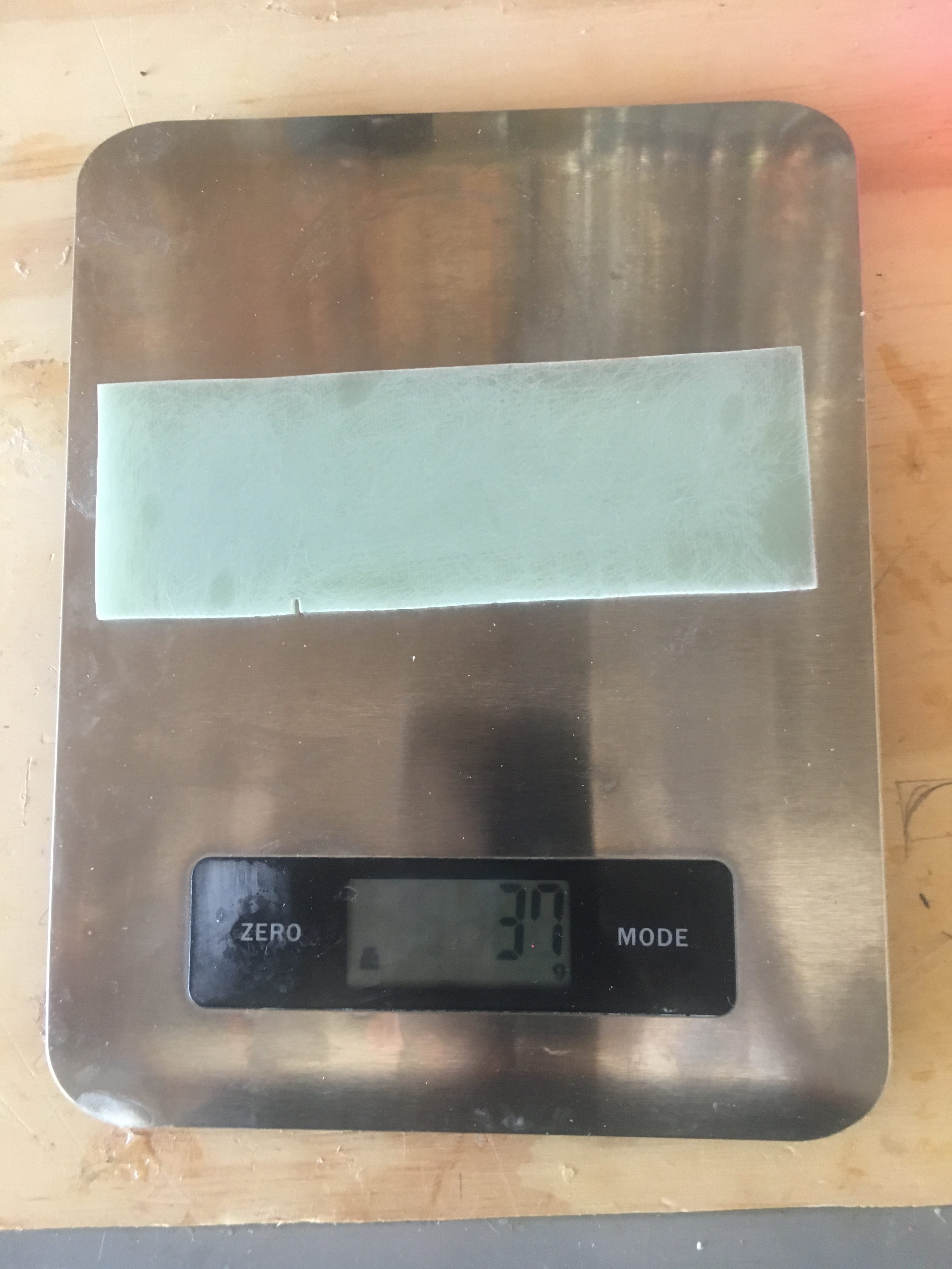
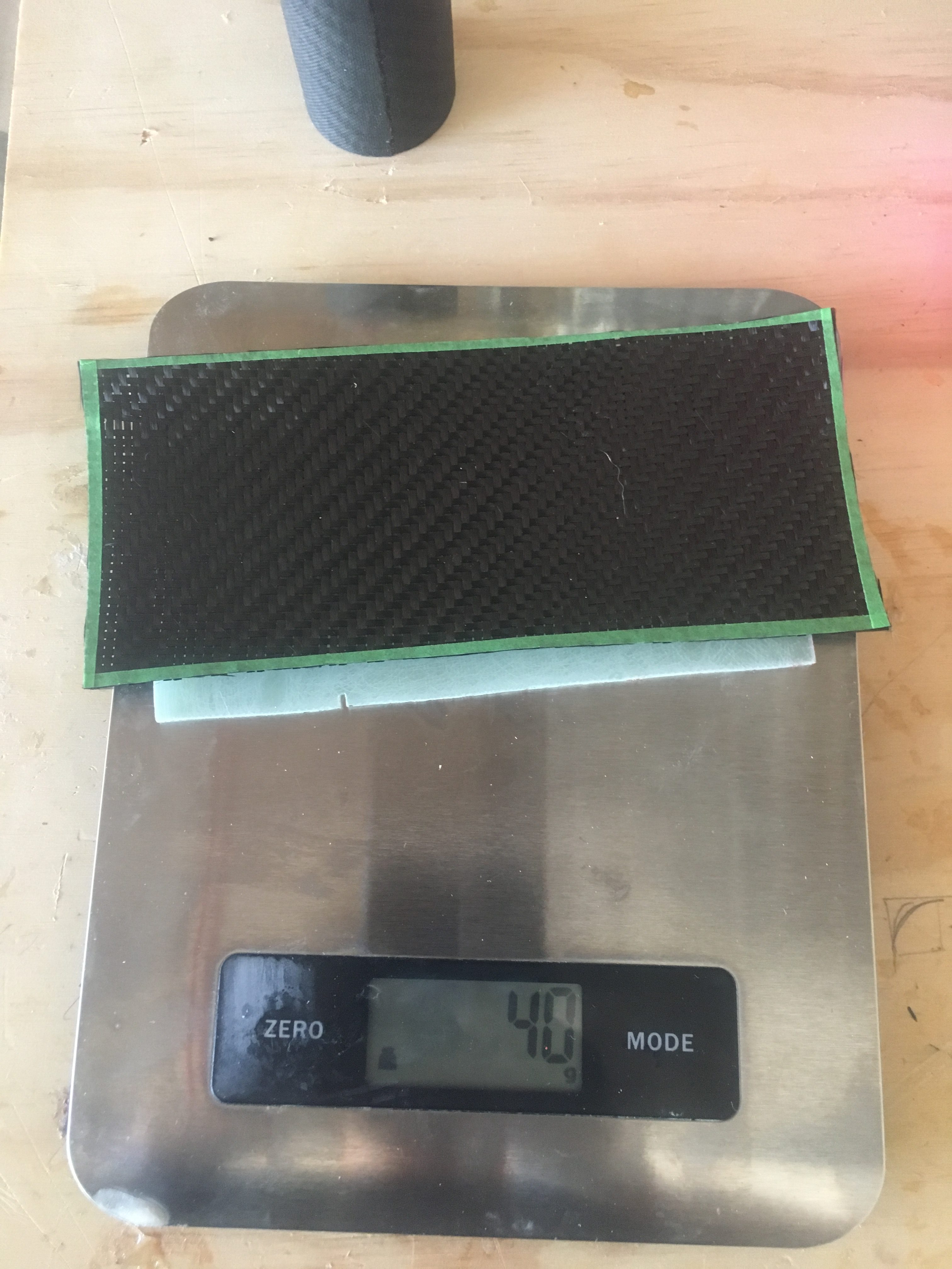
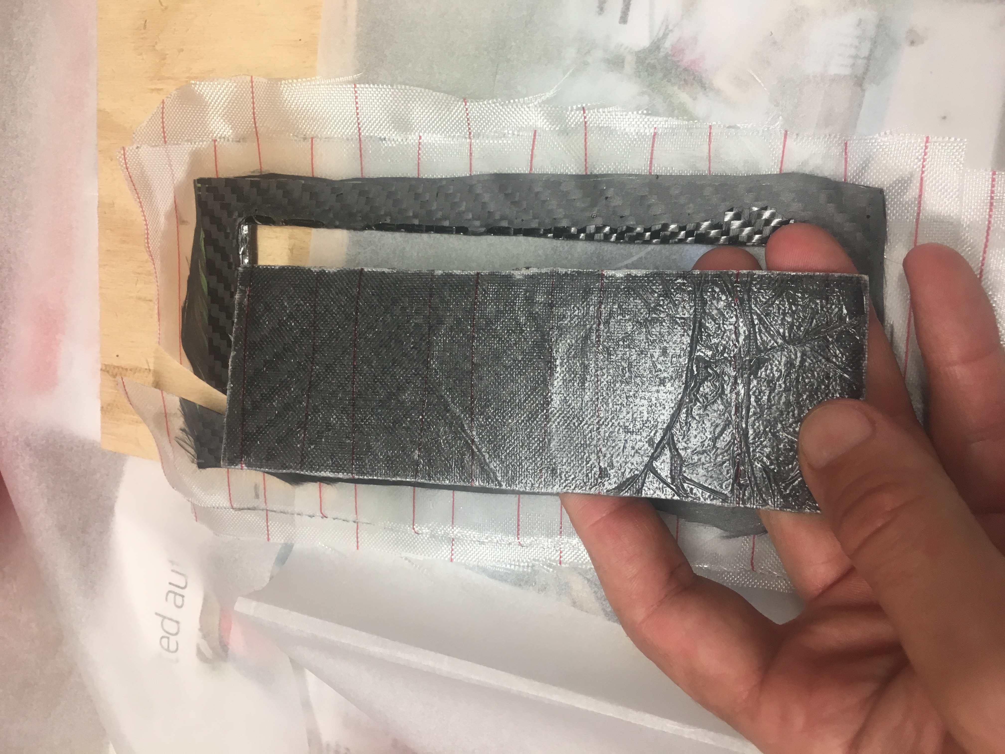
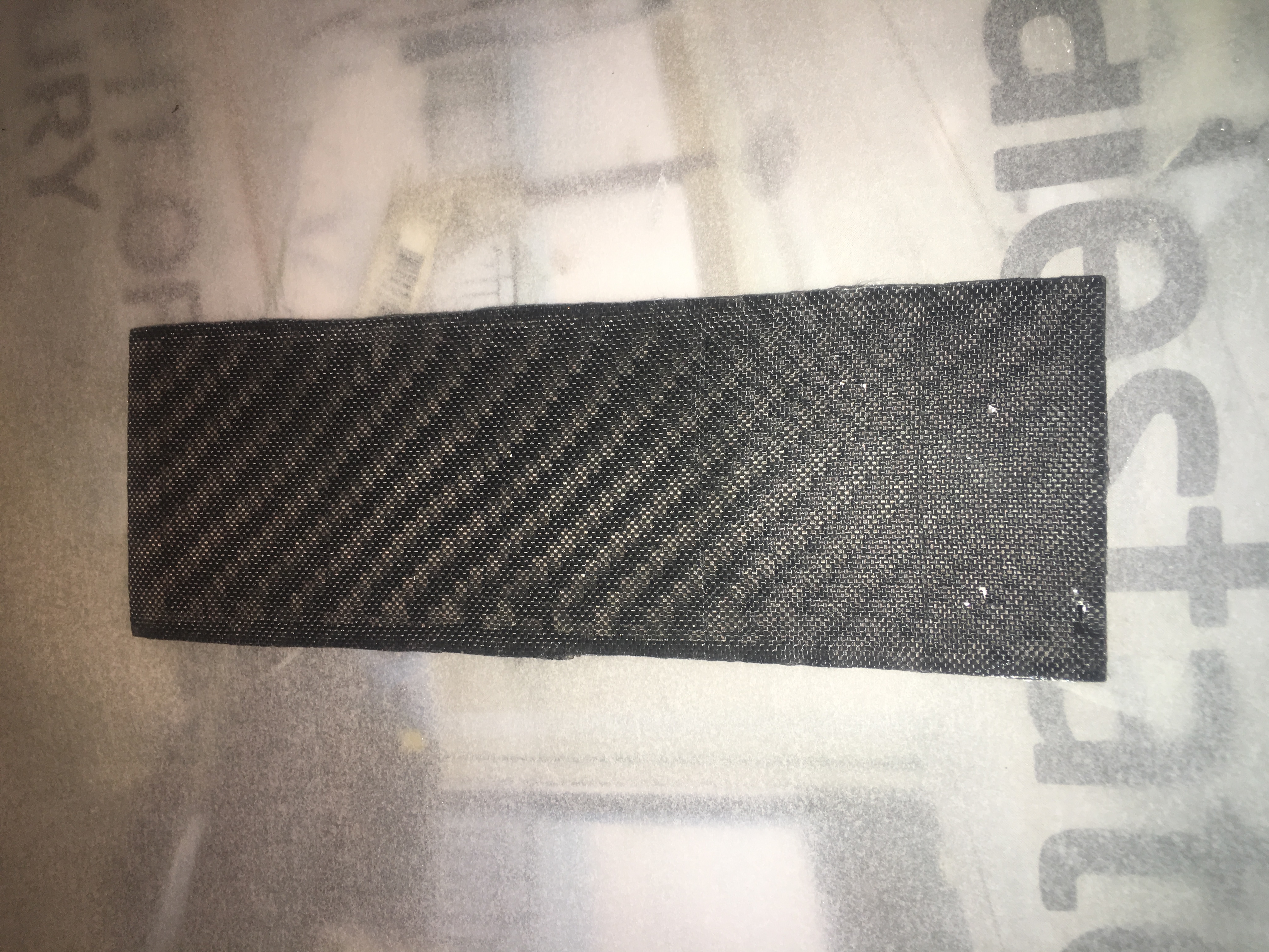
I sanded the entire surface of the fins with Grit 60 sand paper. This is so that the epoxy fillets adhere well to the fins and also so the CF Fin-to-Fin material adheres properly.
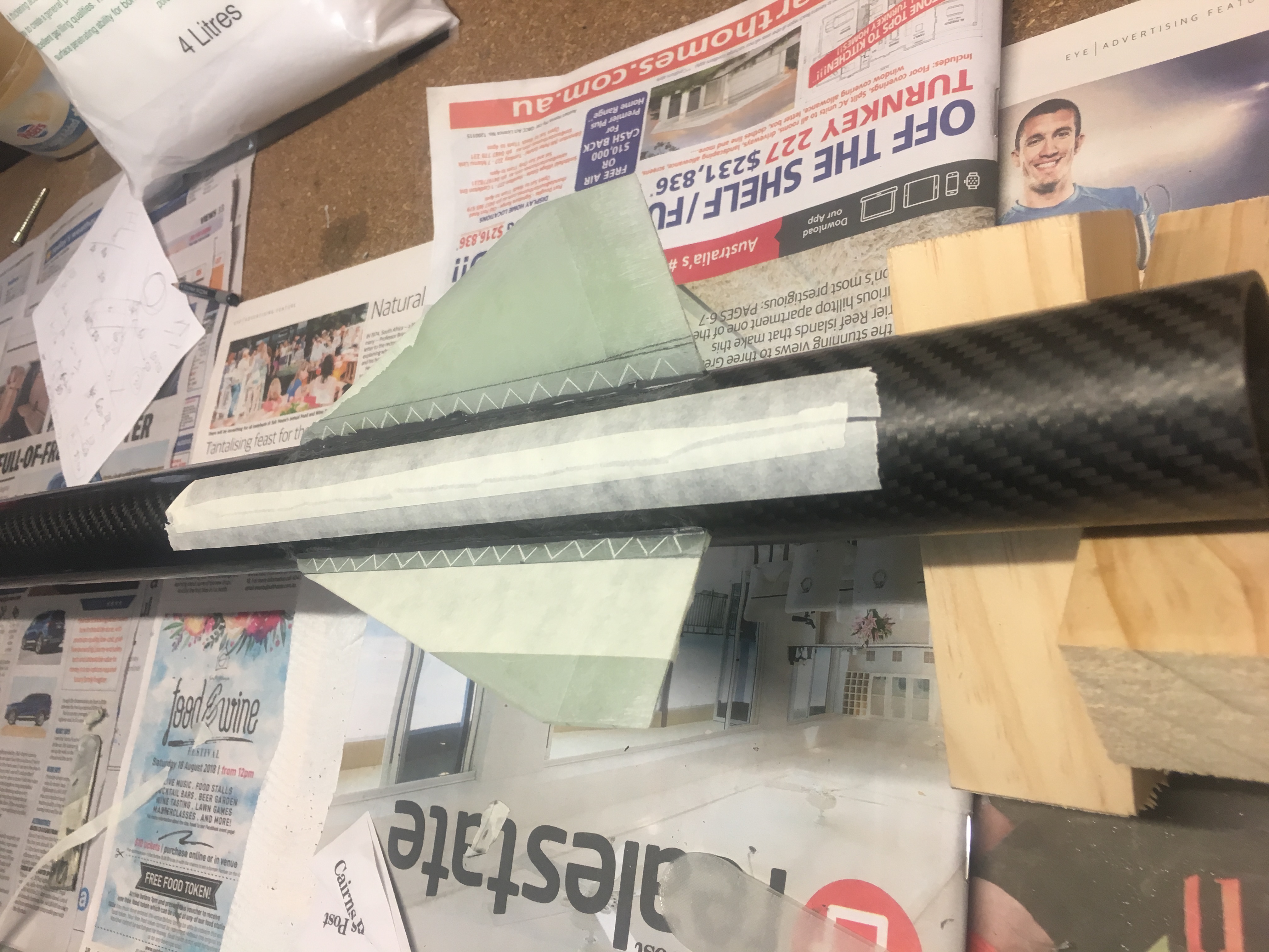
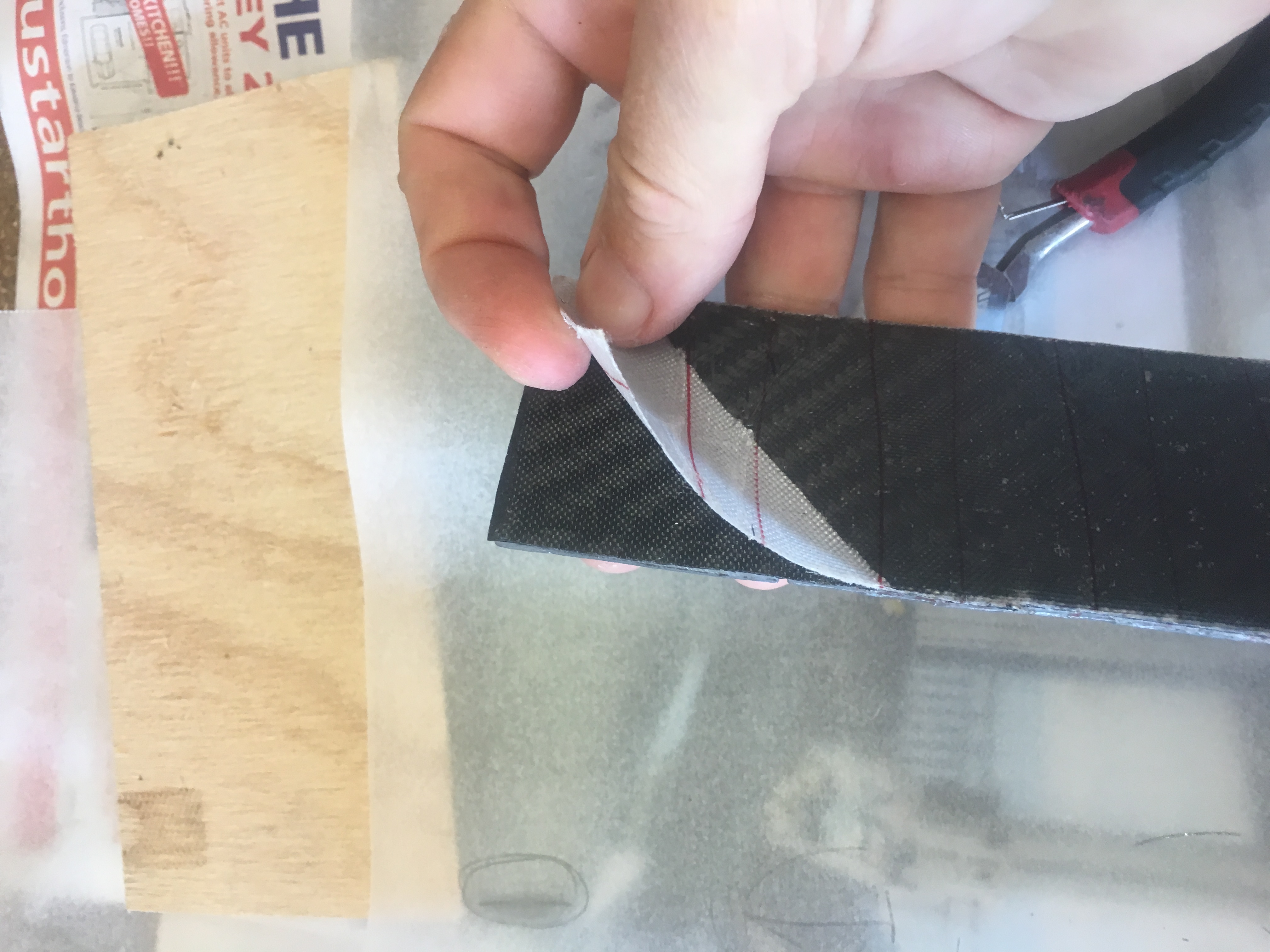
Little cuts were made on the root of the fin every 10 mm, approx 1 mm deep with a hack-saw to encourage a good bond to the air-frame.
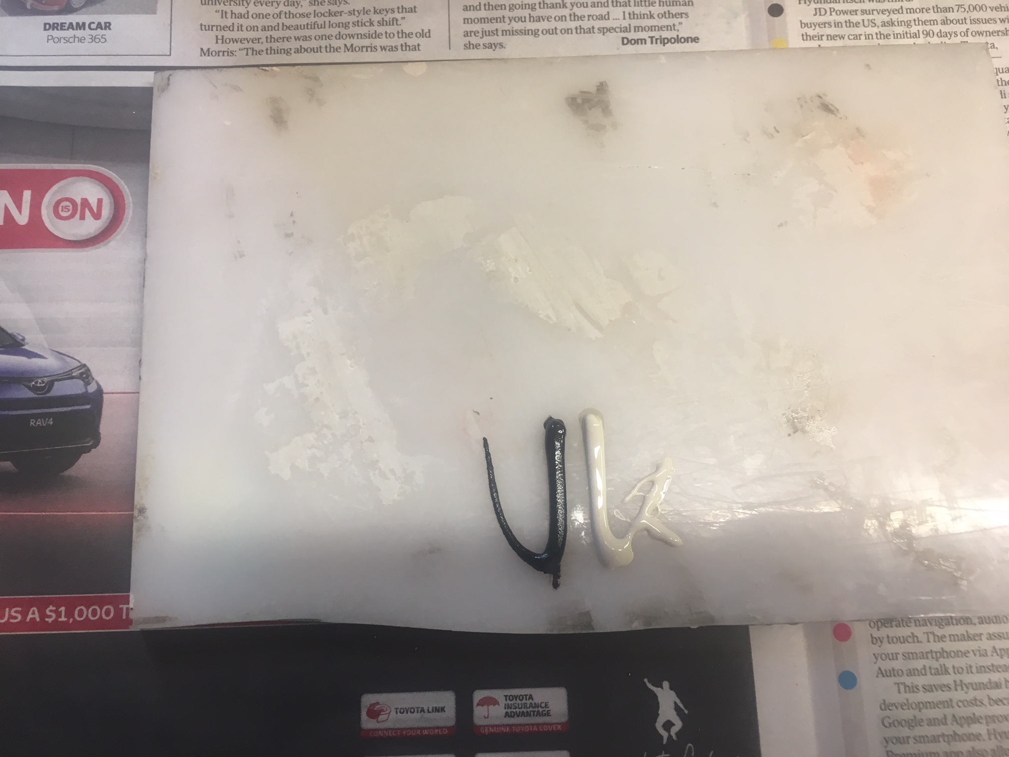
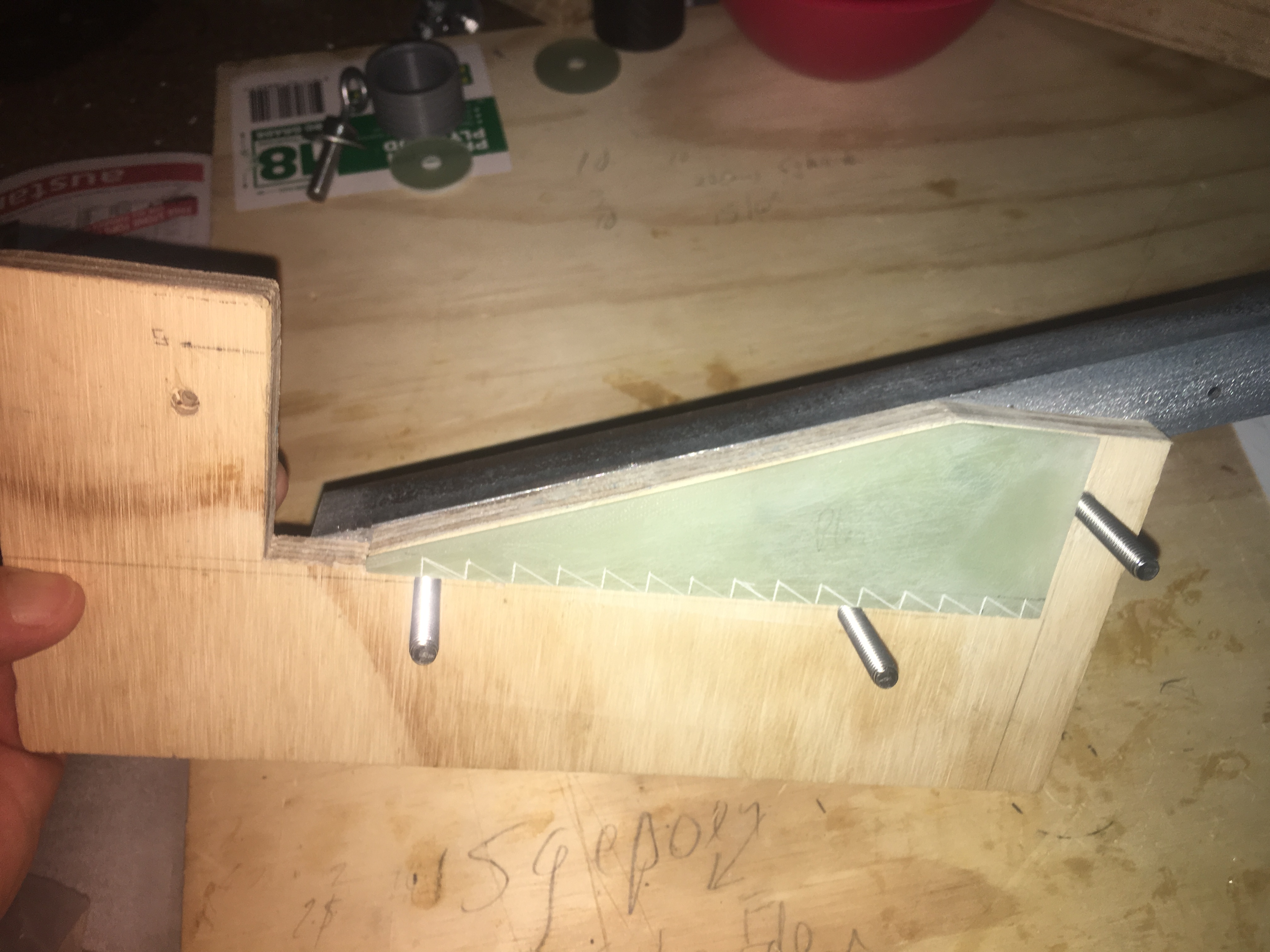
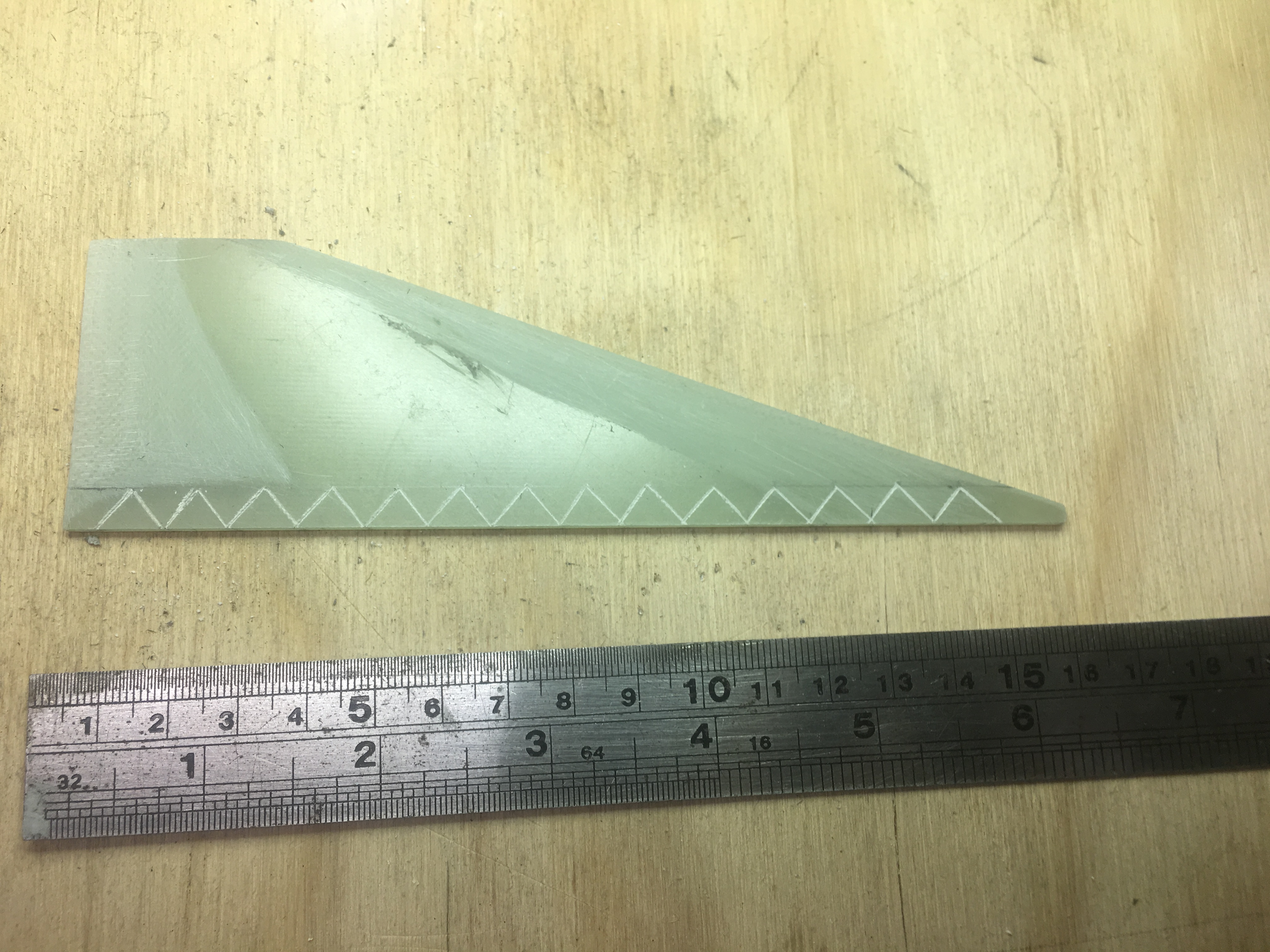
I also scribed 45 degree incisions every 10 mm from the root, to ~7 mm up from the root. This provides extra place for the epoxy fillet to ‘grab’ on to the fins. I used the following “tool” to do this.
Here is a photo of one of the fins I scored.
I also used a hack saw to cut 1mm deep incisions into the root of the fin every 10mm. No photo available.