Performing Ejection Tests

38mm CTI and AeroPak motors come buy default with approx 1.4 grams of Black Powder for their ejection charges. Based on this and the fact my rocket has half of volume blocked off by engine block, I decided to start my ejection charge tests at 0.75 grams. Ultimately I got up to 1.76 grams of BP. This post discusses this in detail.


How the system is packed.

This is probably the best place to describe how the recovery system was packed, because the tests identified a possible issue with the set-up.
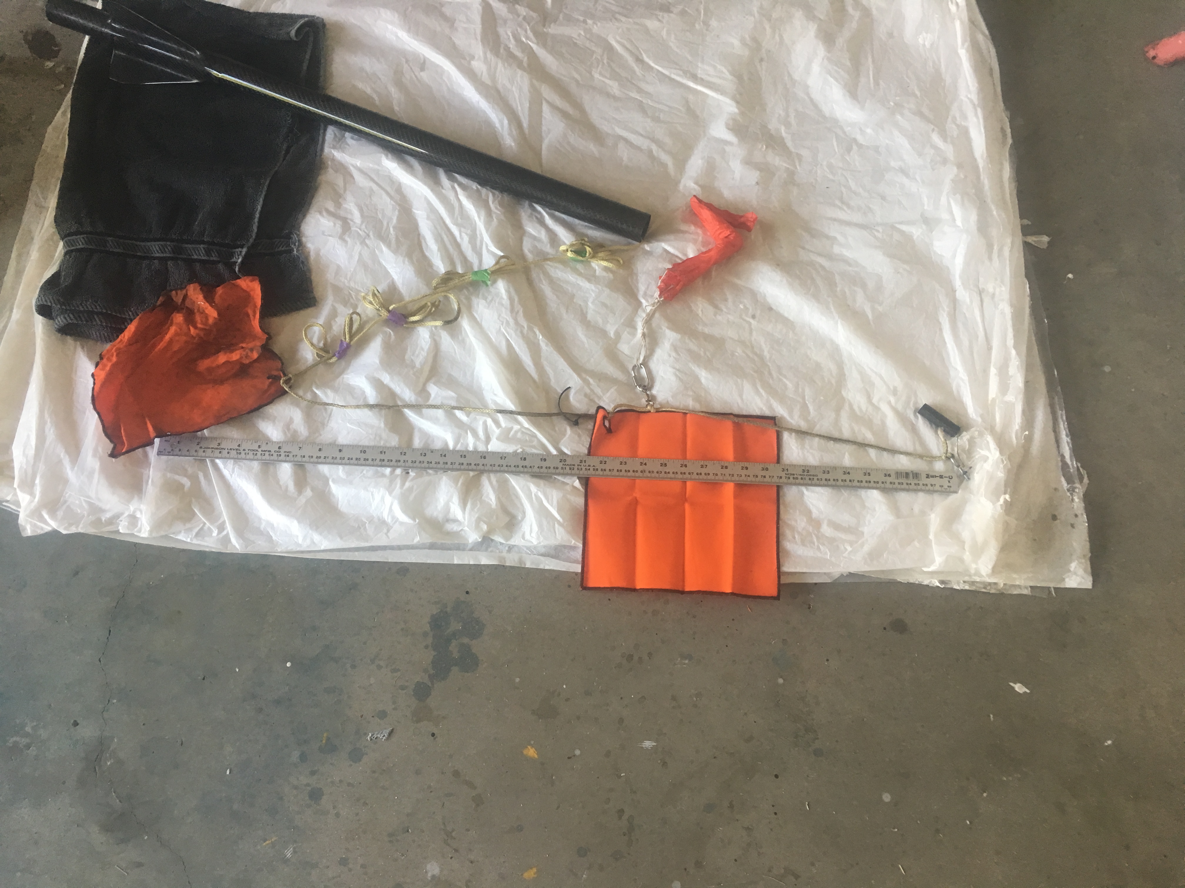
View of all the components to be packed into air-frame - prior to folding and attaching igniters, cable cutter.
View of all the components to be packed into air-frame – prior to folding and attaching igniters, cable cutter.

You will notice in this photo there are TWO Nomex blankets. The left oneĀ  covers the shock-cord (but its primary purpose is add additional drag) and the other Nomex blank protects the parachute. The right Nomex blanket is held in place with a Cable Cutter, the right is simply wrapped into a bundle.

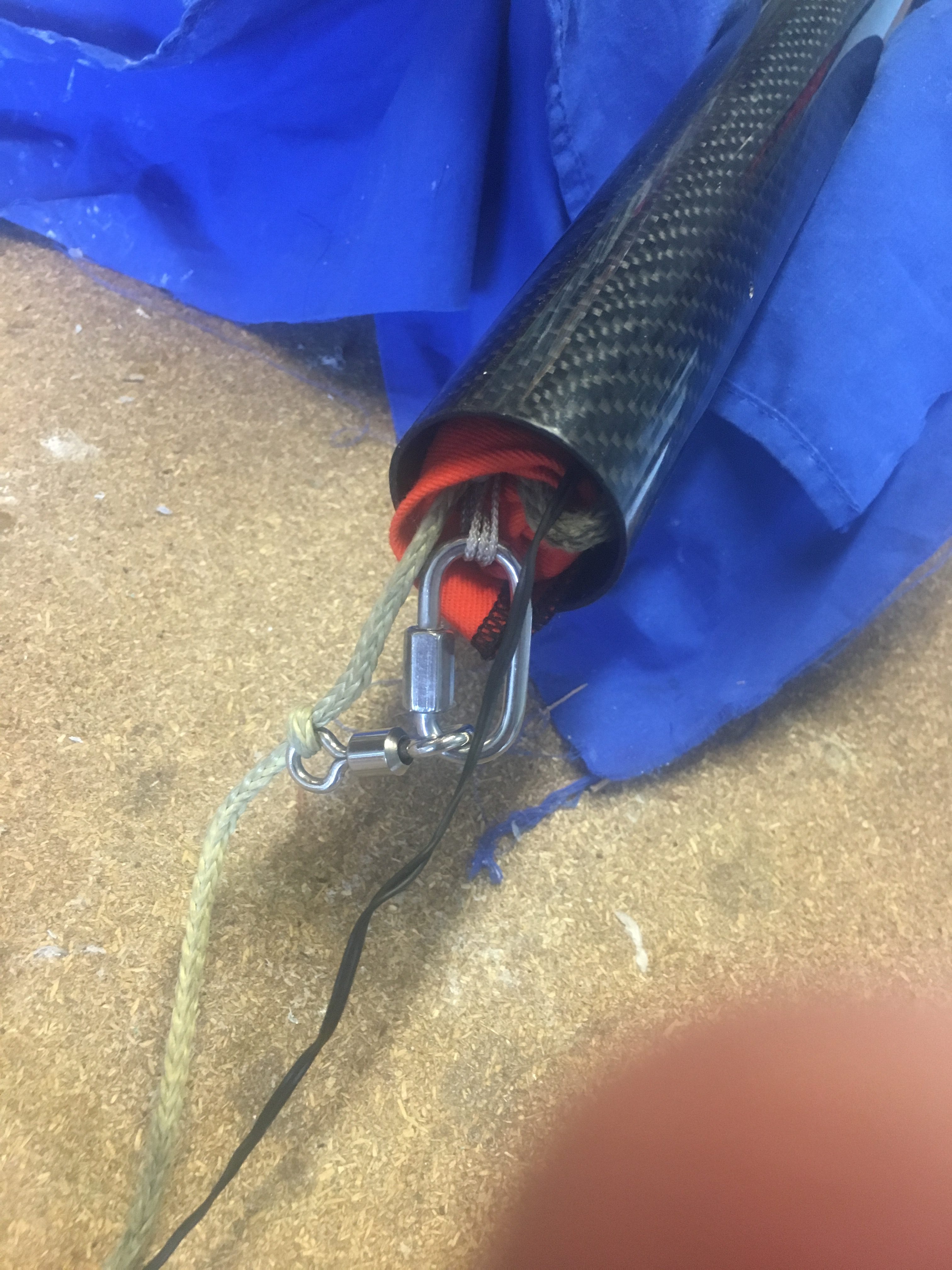
The parachute is on a Swivel and uses a 4mm Quick-Link. The Shock-cord is 5 metres in length, with 0.5 meters inside the air-frame. Notice the use of Z-Folds.


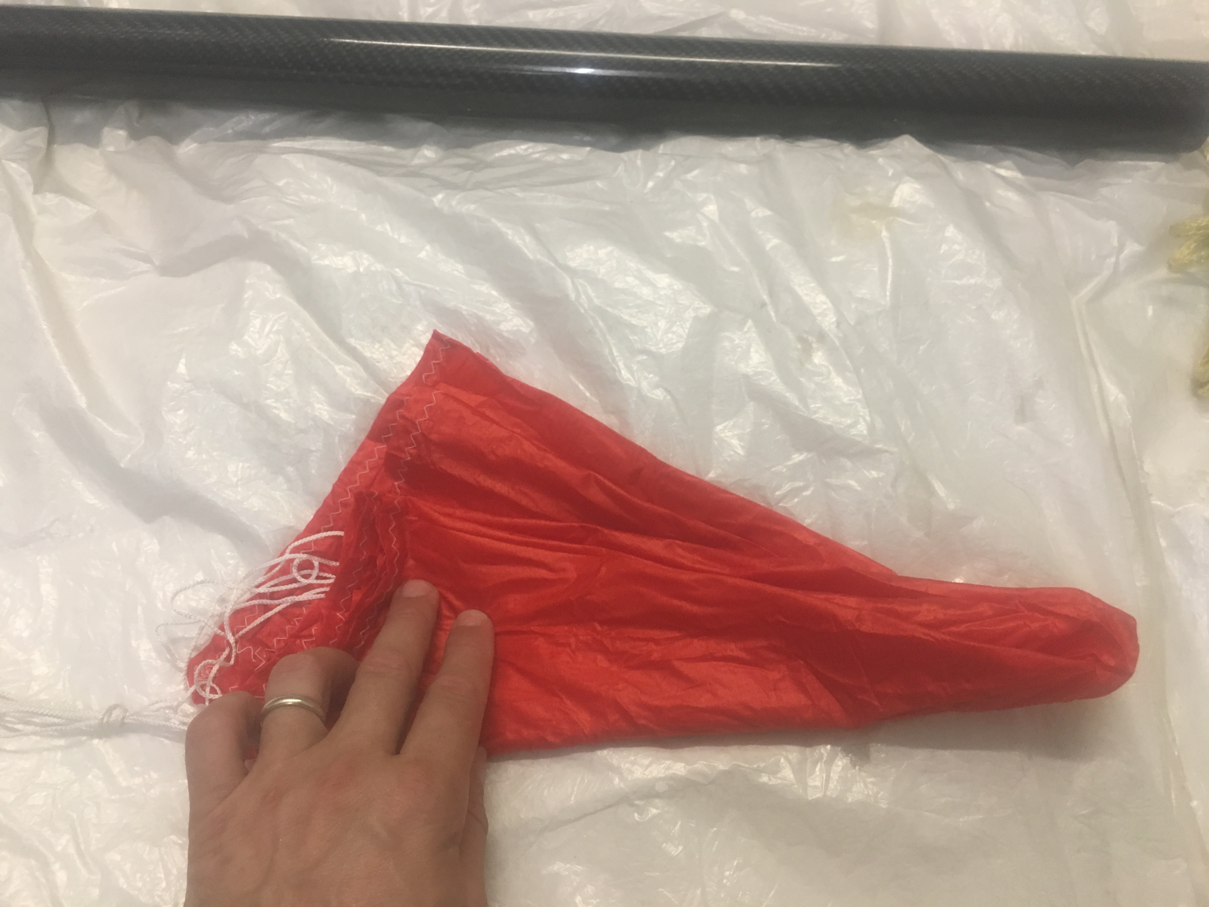
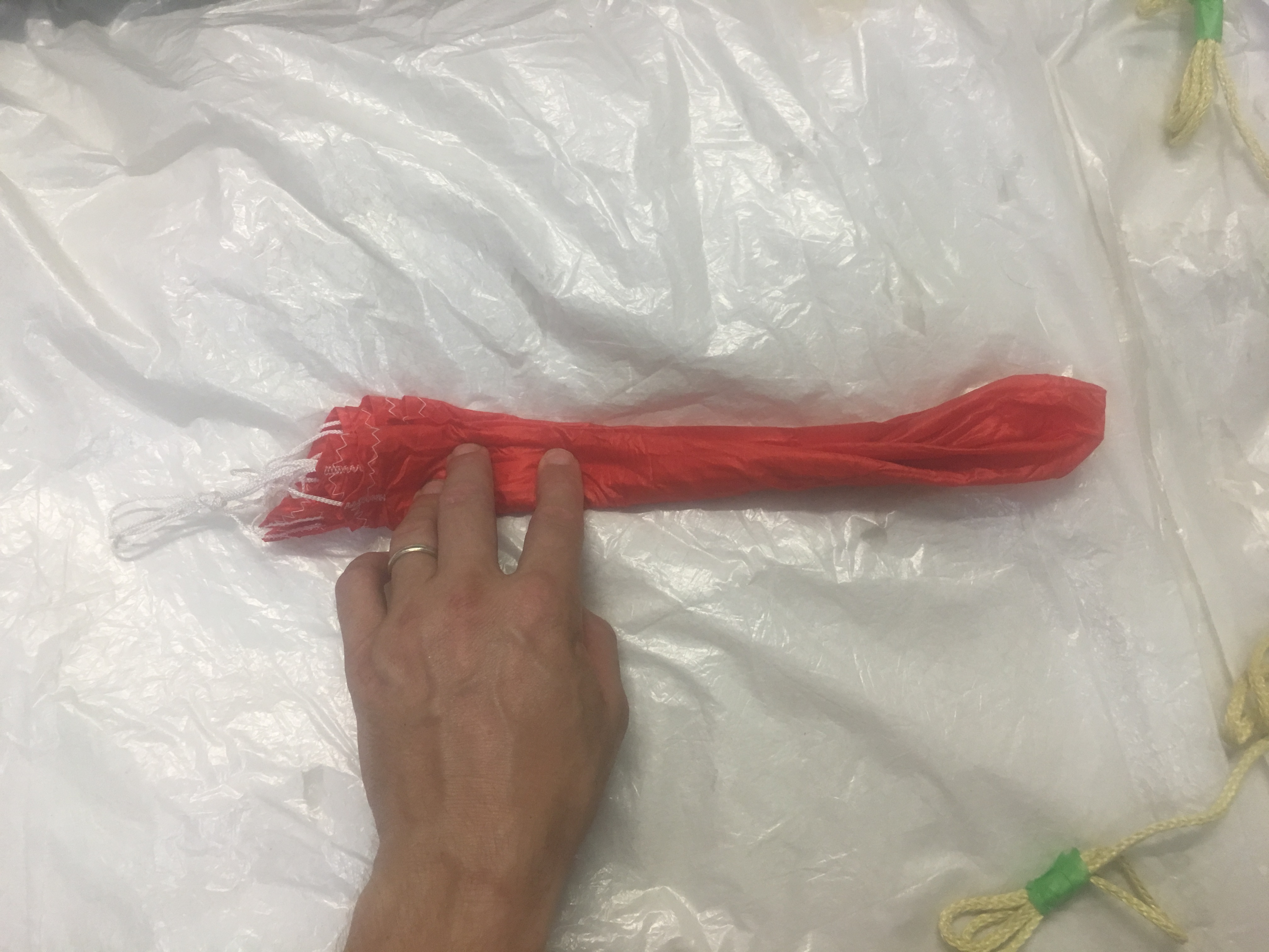
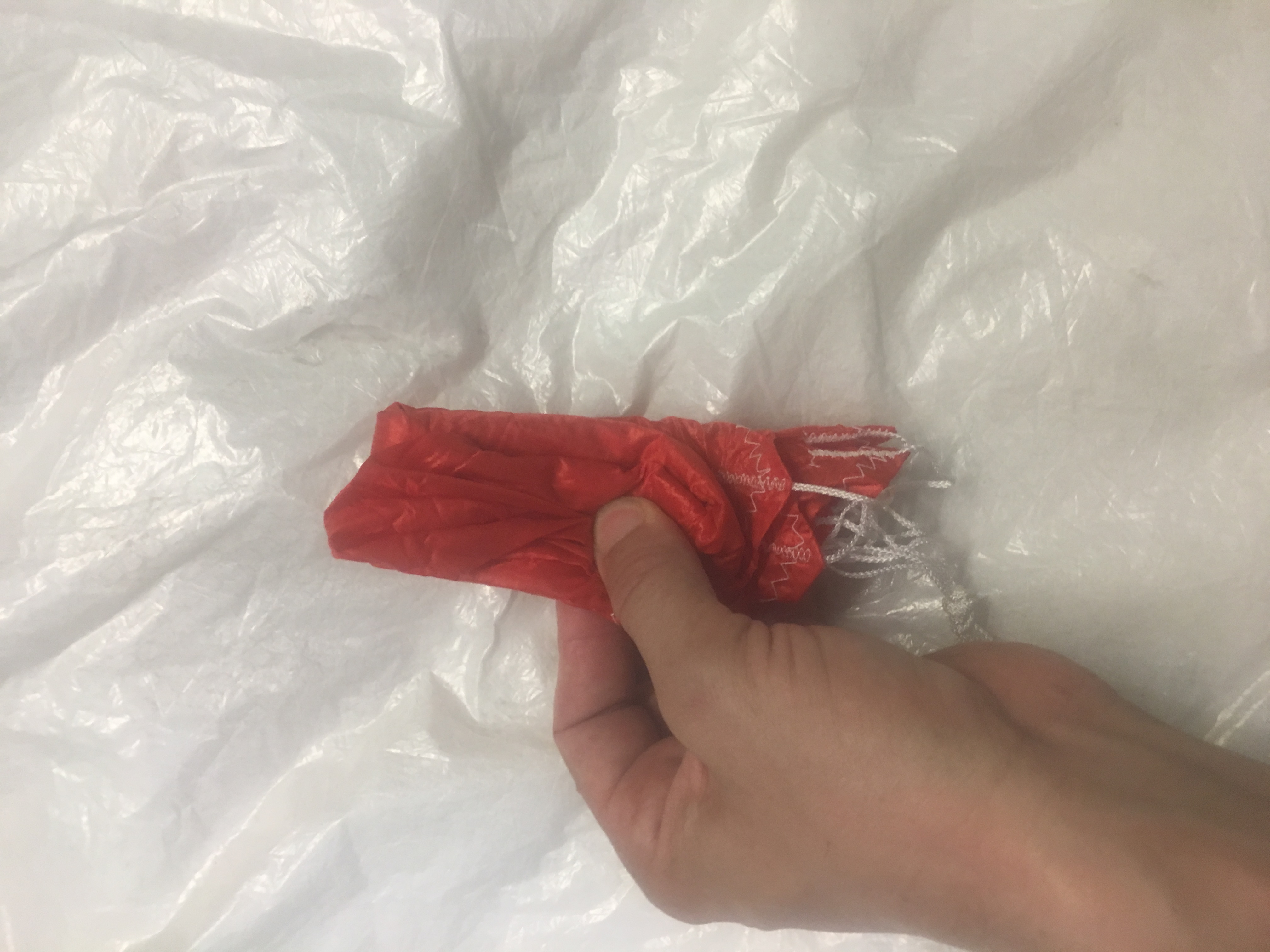
How the Parachute is folded

Here are some photos of how it was folded.
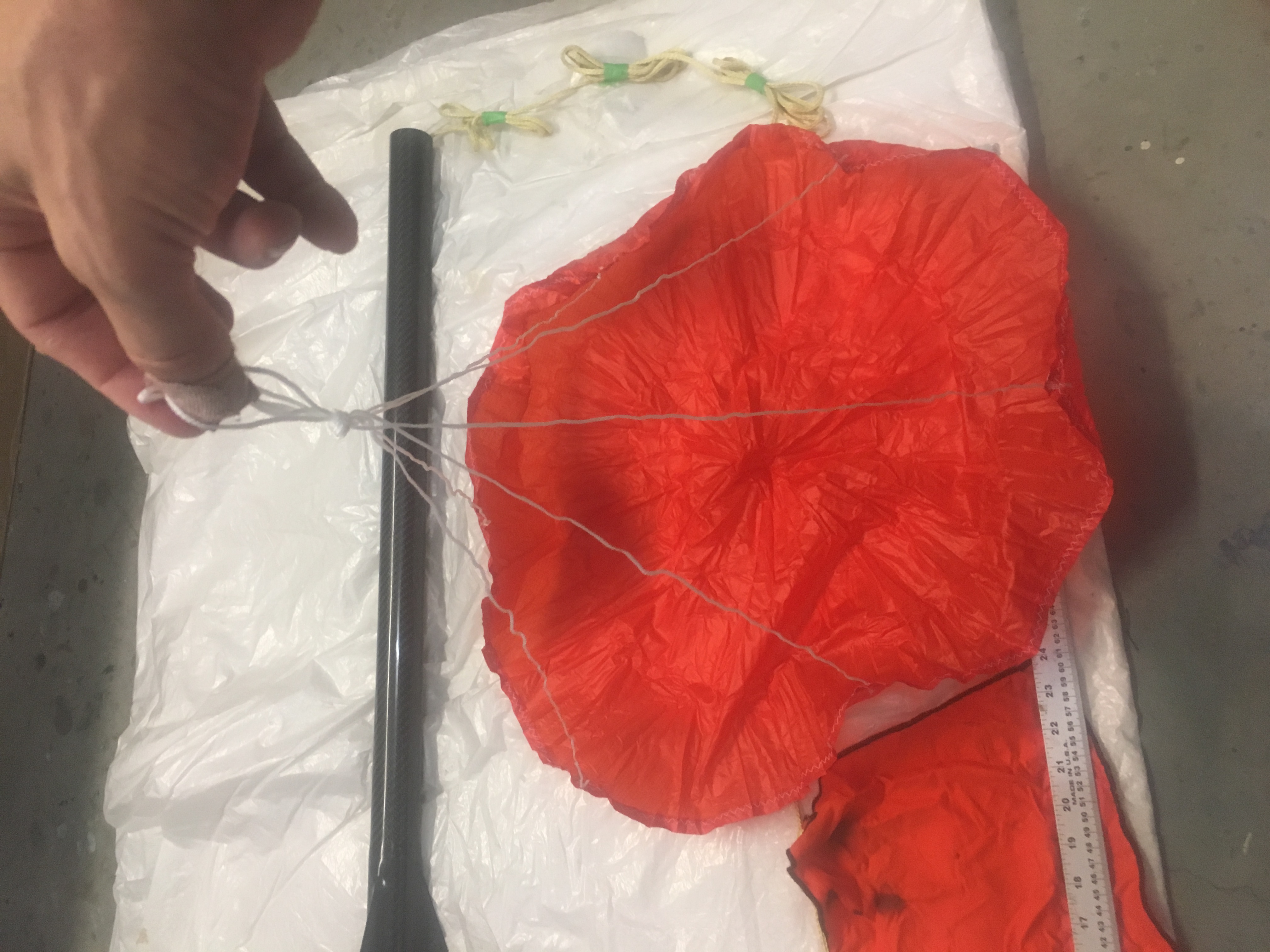
Making sure parachute has no damage and shroud lines are not tangled.
Laying out the parachute, shroud lines taut.


Making sure all the parachute gores are equally aligned.
Making sure all the parachute gores are equally aligned and neat.
Ensuring all gores are split evenly on each side of the shroud lines.
Putting most of shroud lines about 3/4 up the parachute skirt.
Folding bottom "third" up....and then top third down.
Folding bottom “third” up….and then top third down.
Folding over again.
Folding over again.
z-folding into three.


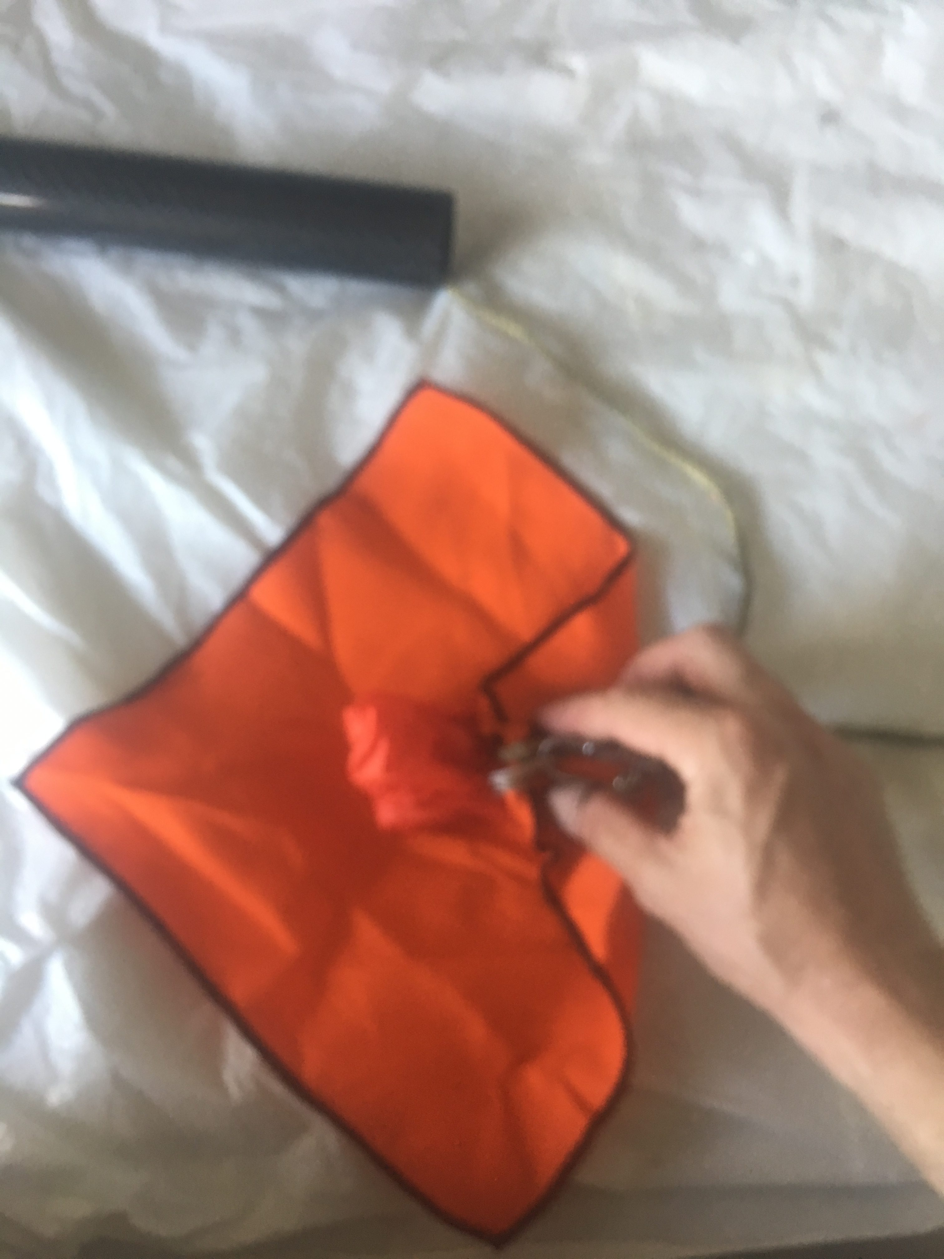
Protecting Parachute with Nomex Blanket
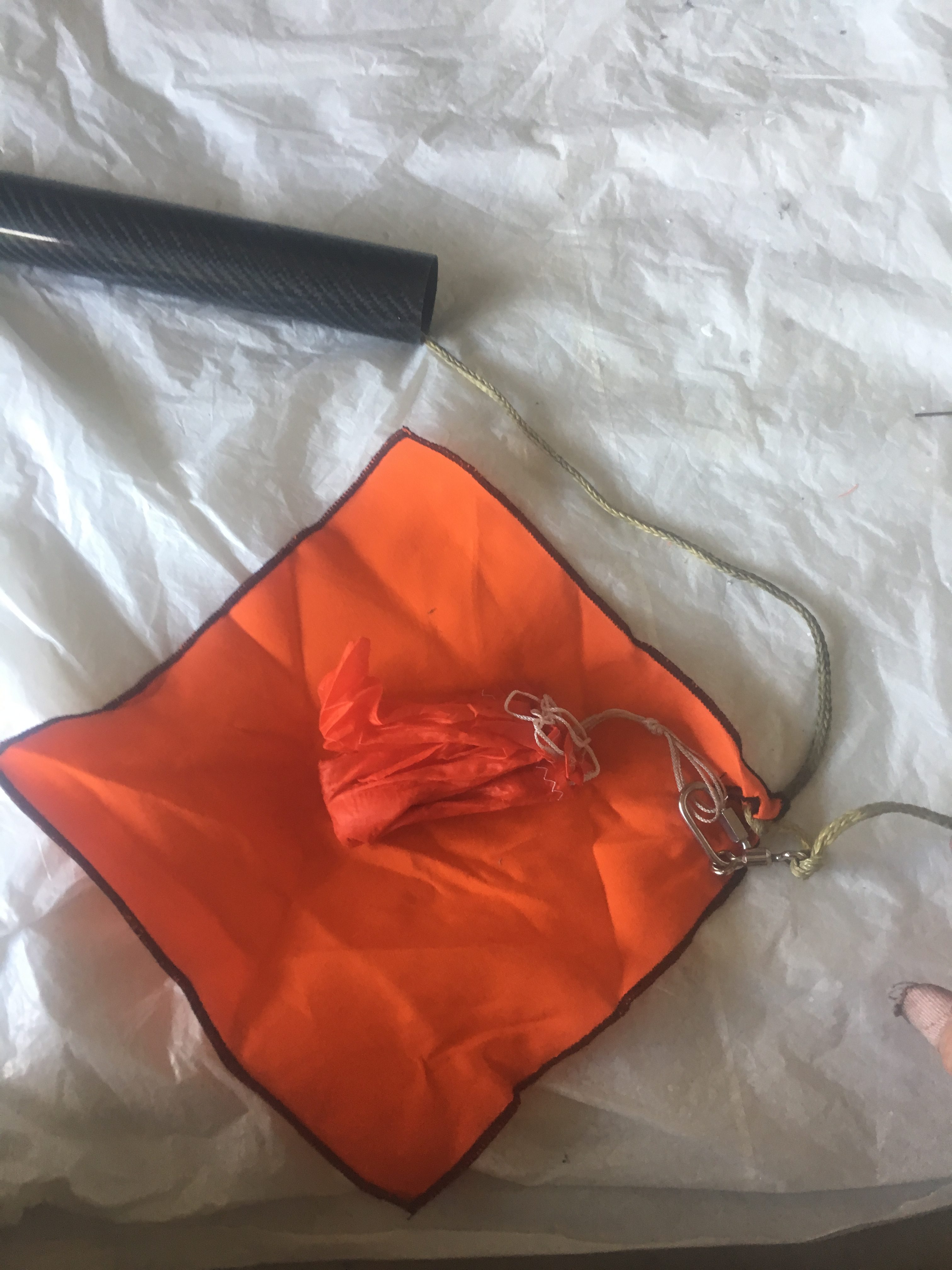
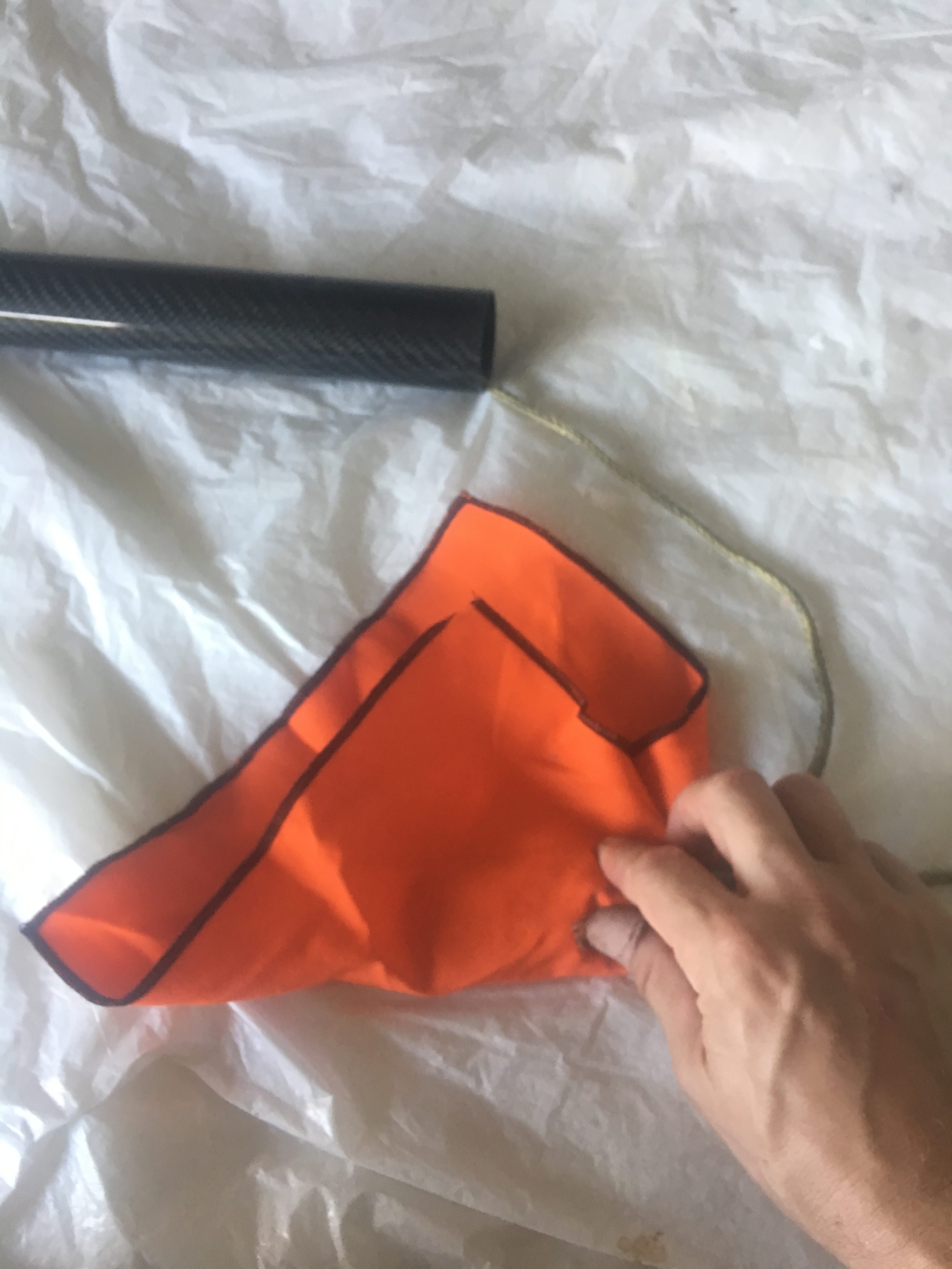
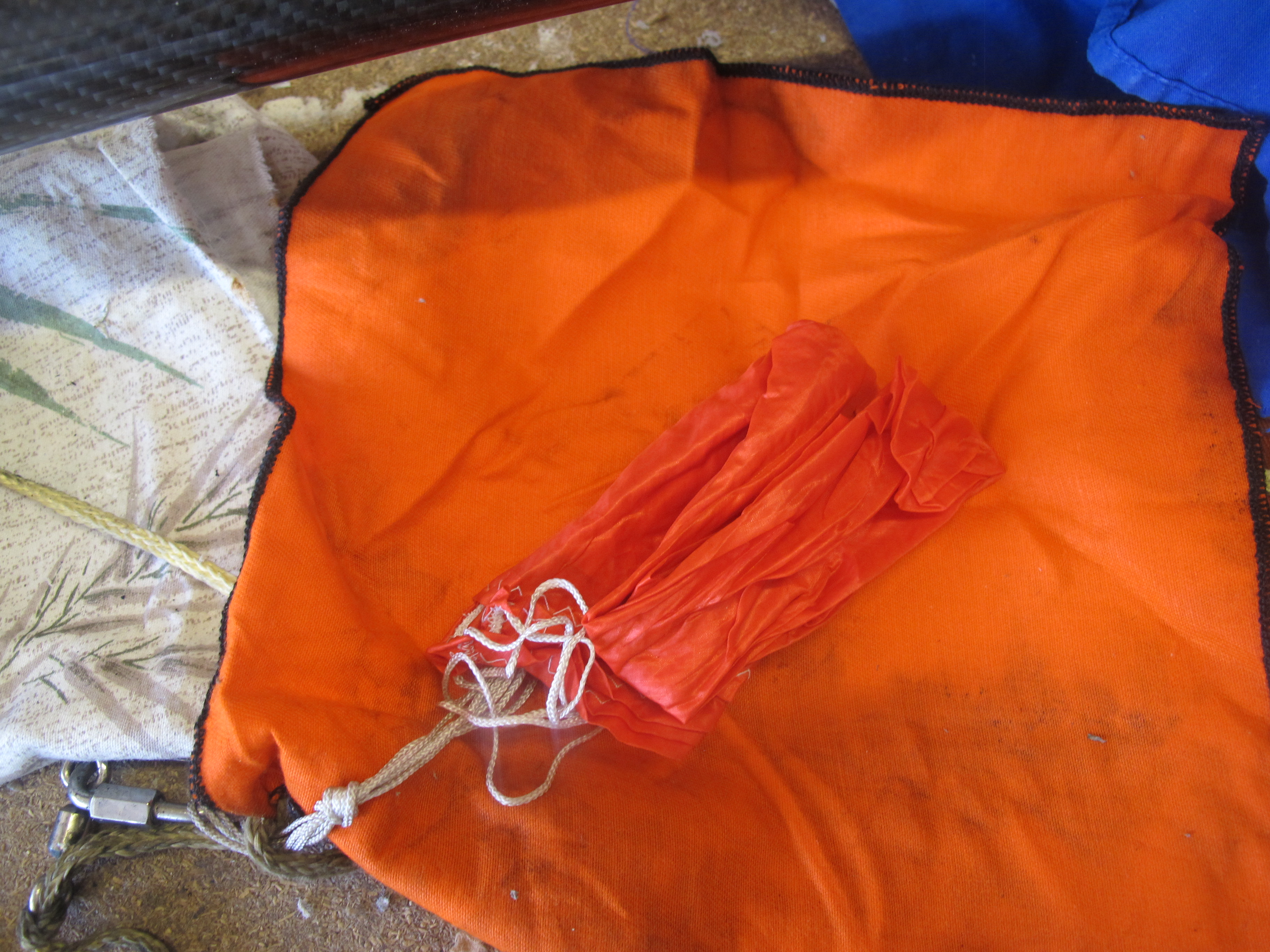
Place bundle in the centre of the Nomex blanket, with the shroud lines pointing to the right. Make sure the quick link is just outside the bundle.


Pardon for lack of focus. Fold from RHS to about 1/3 way left.
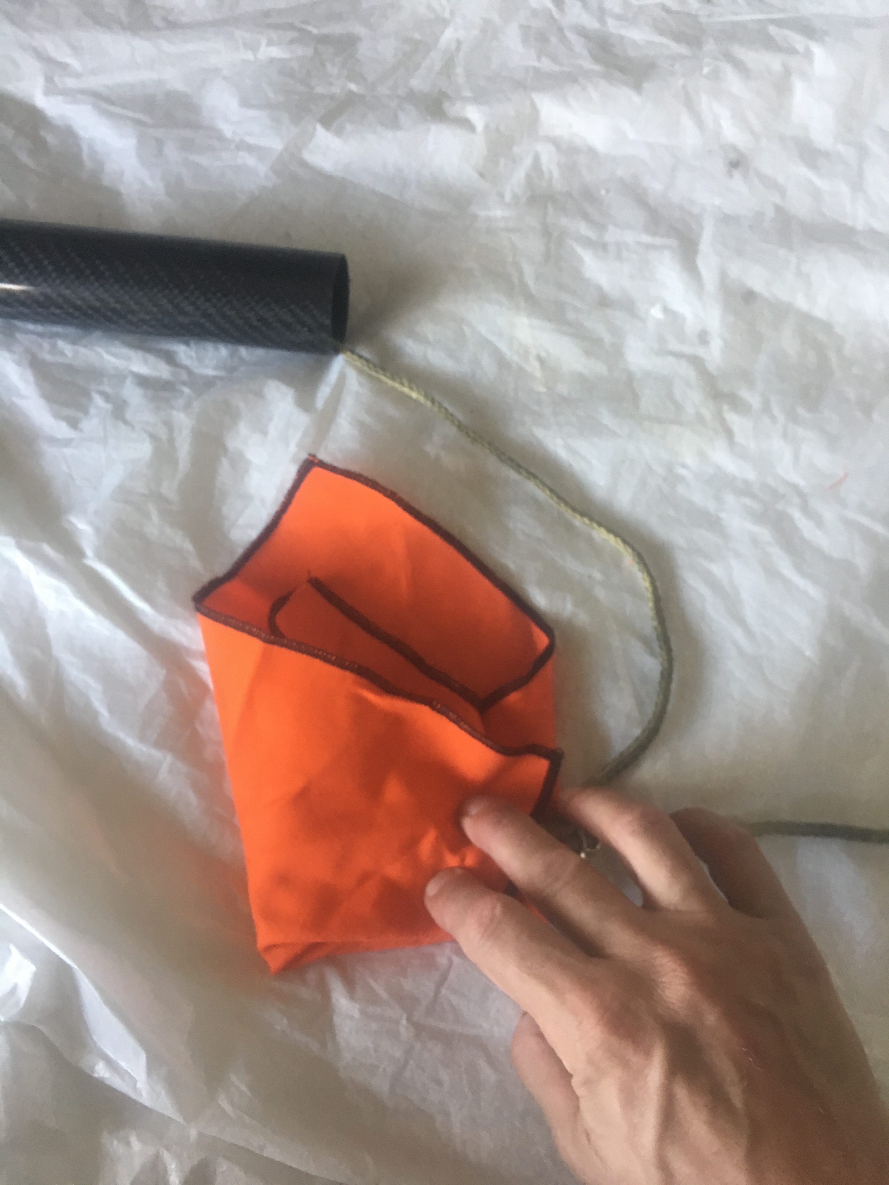
Fold bottom up
Fold bottom up
Fold Left piece to the right. The tightly role up.
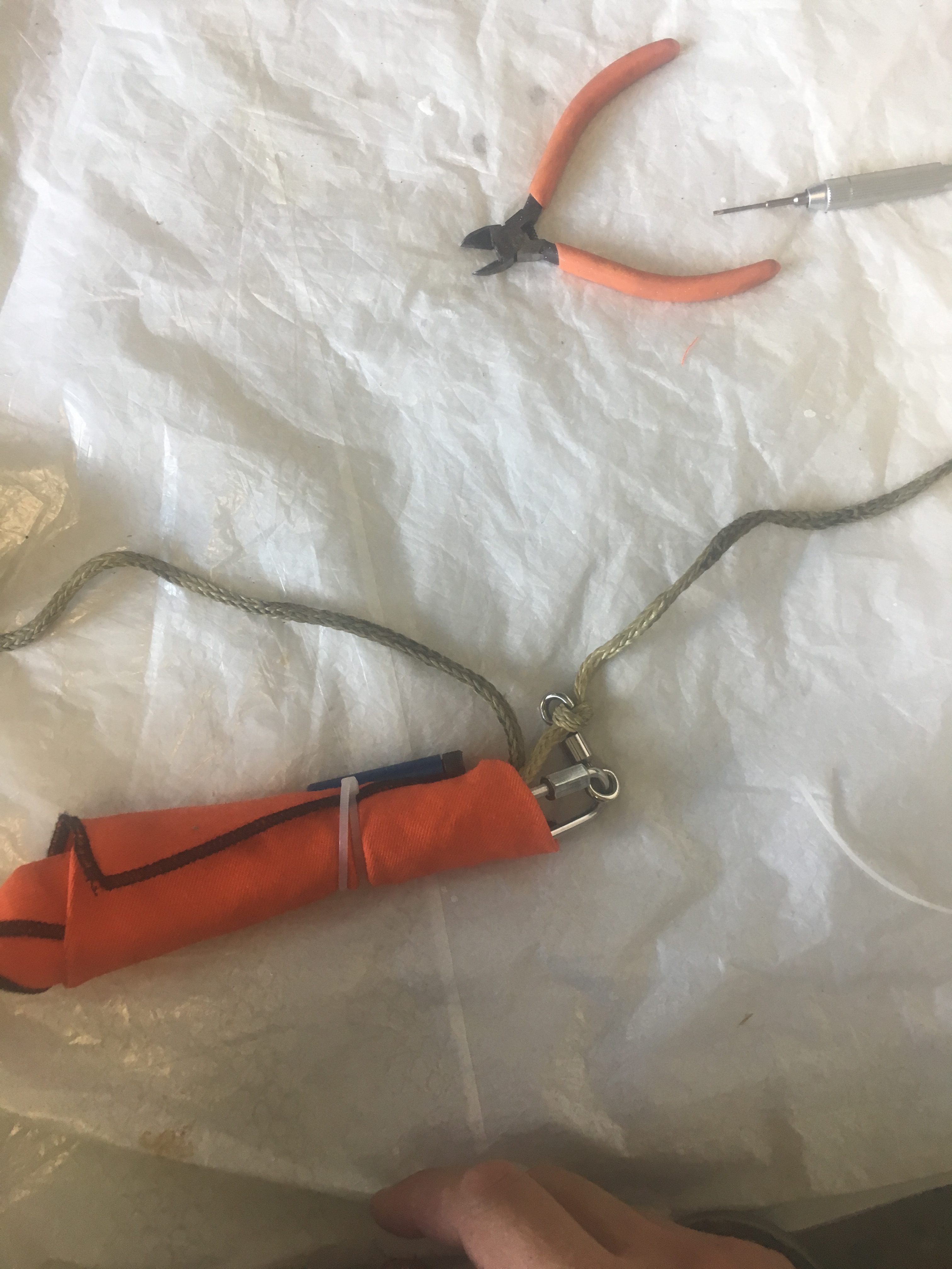
Place the Cable Cutter/cable Tie around it. Make sure the screw/end is at shroud end.

I made double sure that the parachute was attached to the shock-cord and the quick link was taped up.

Loading the recovery systems into the Air-frame.

Here are some photos of how I did it.
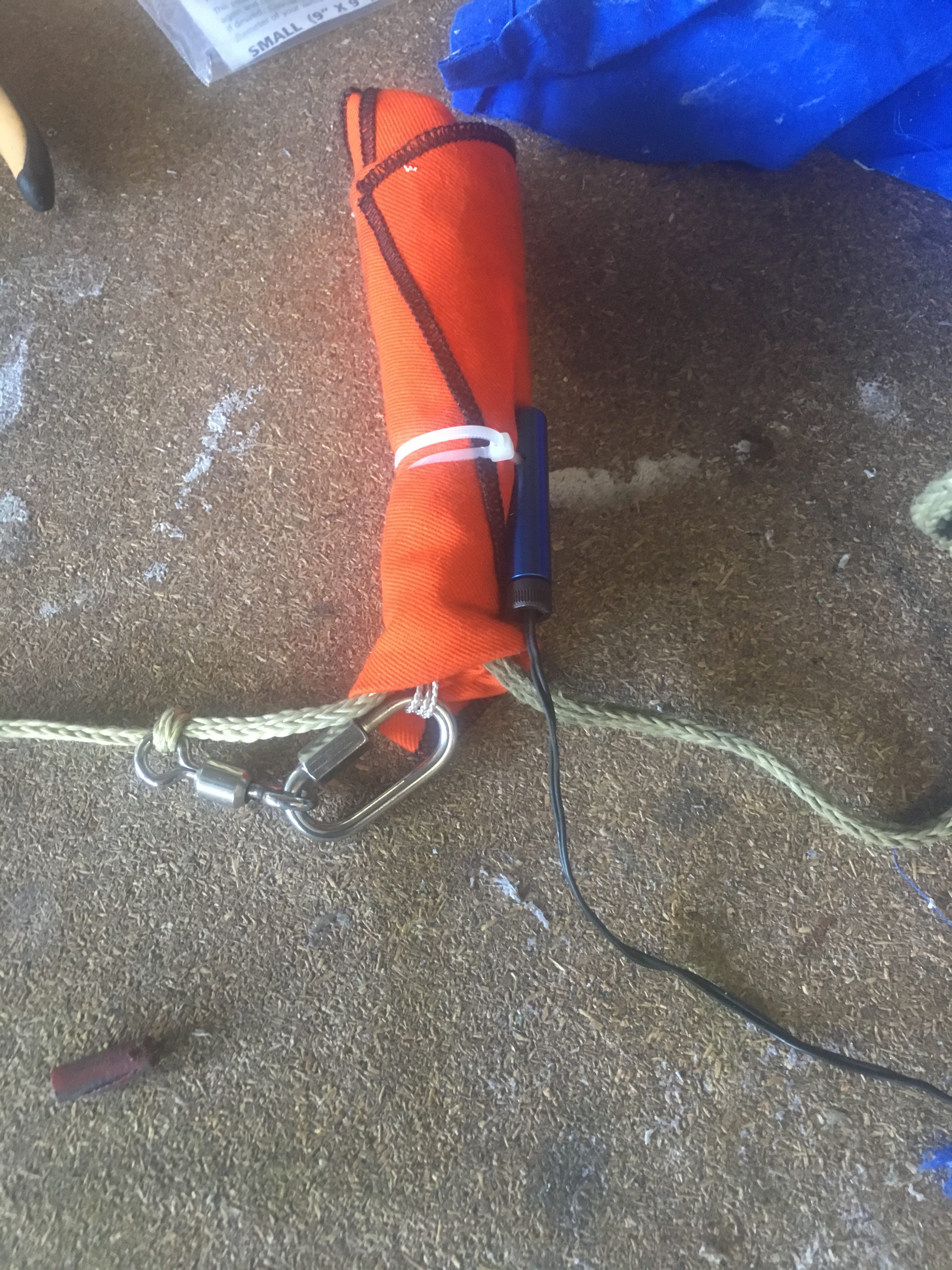
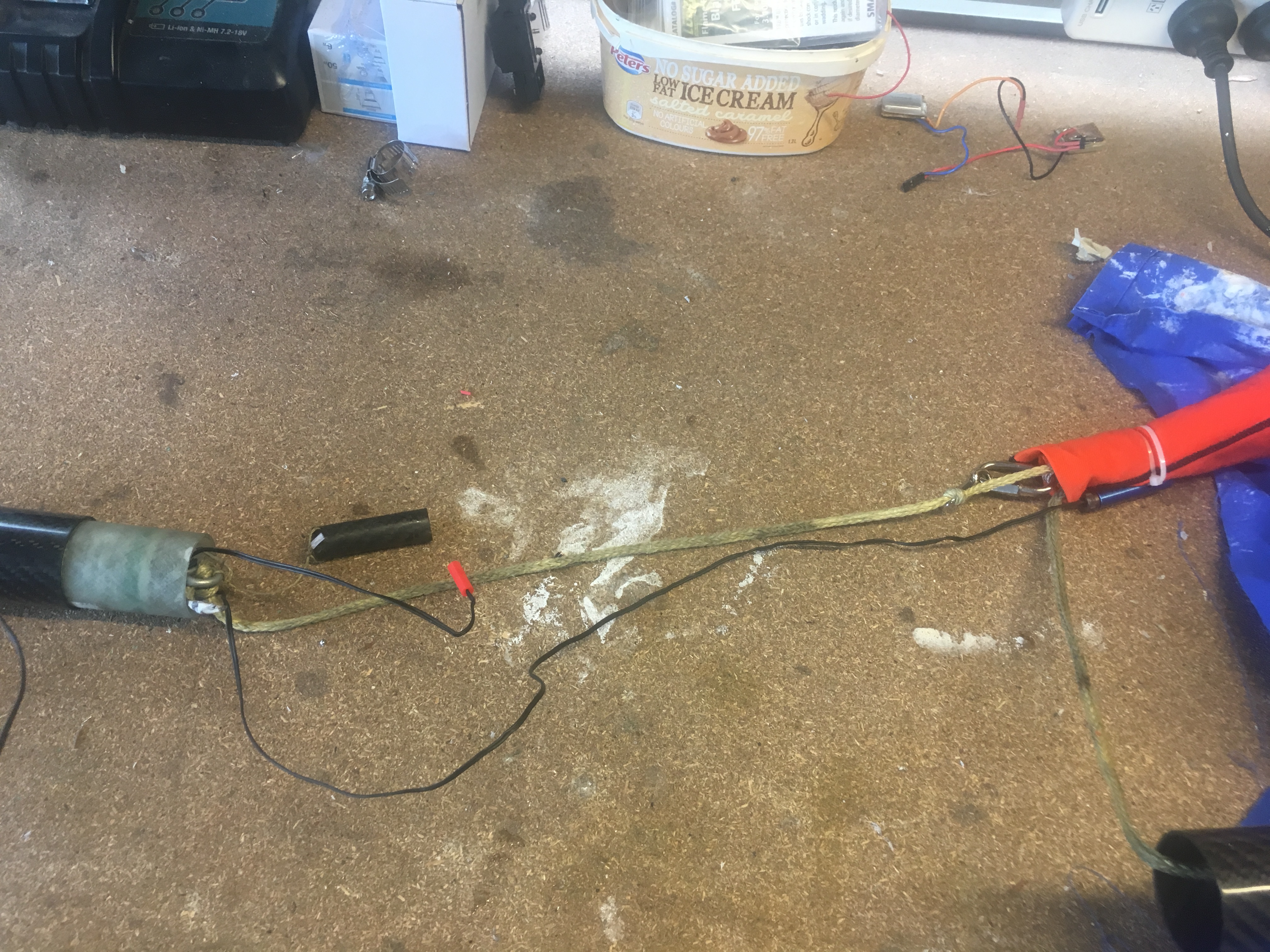
3rd test: Checking that there is chance of cable cutter migrating further away from the nose cone.
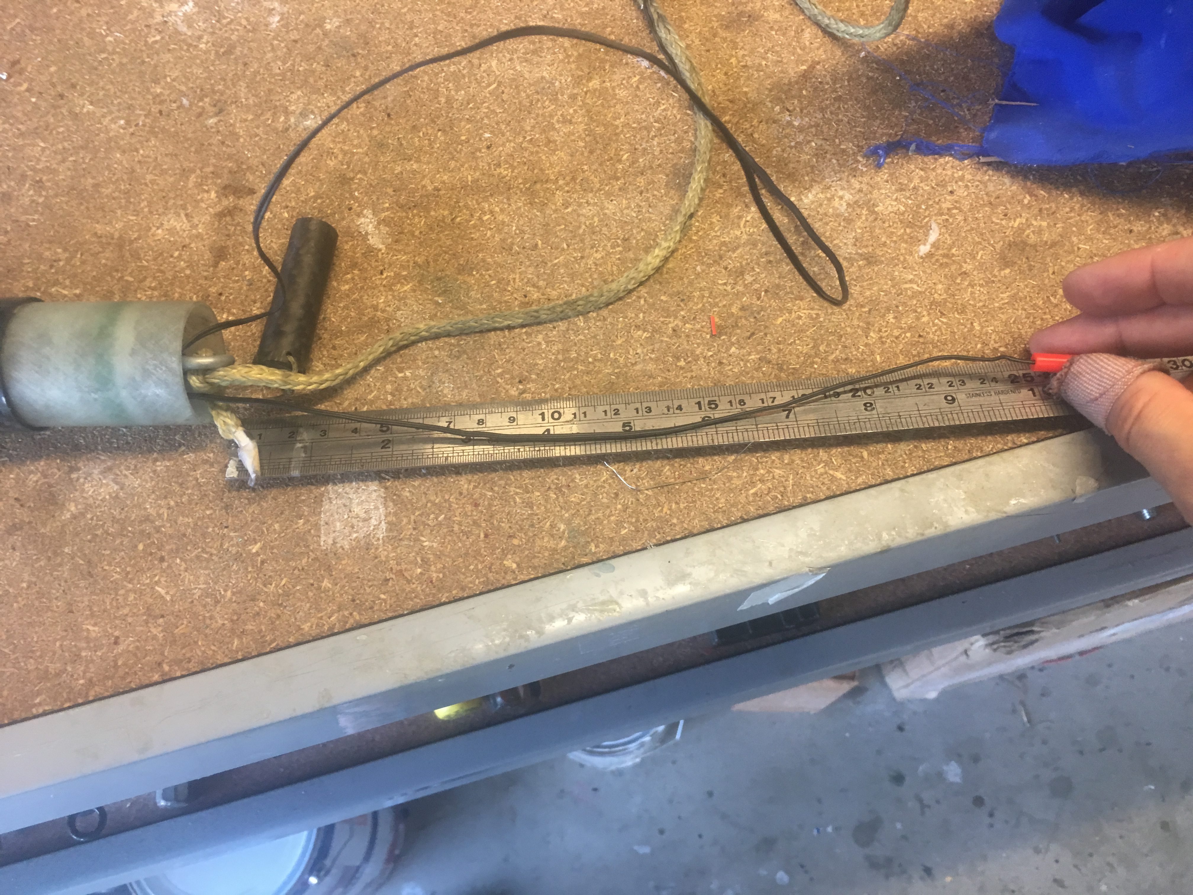
3rd Test: Measuring length of igniter for Black Powder Charge well. Should be about 27cm.
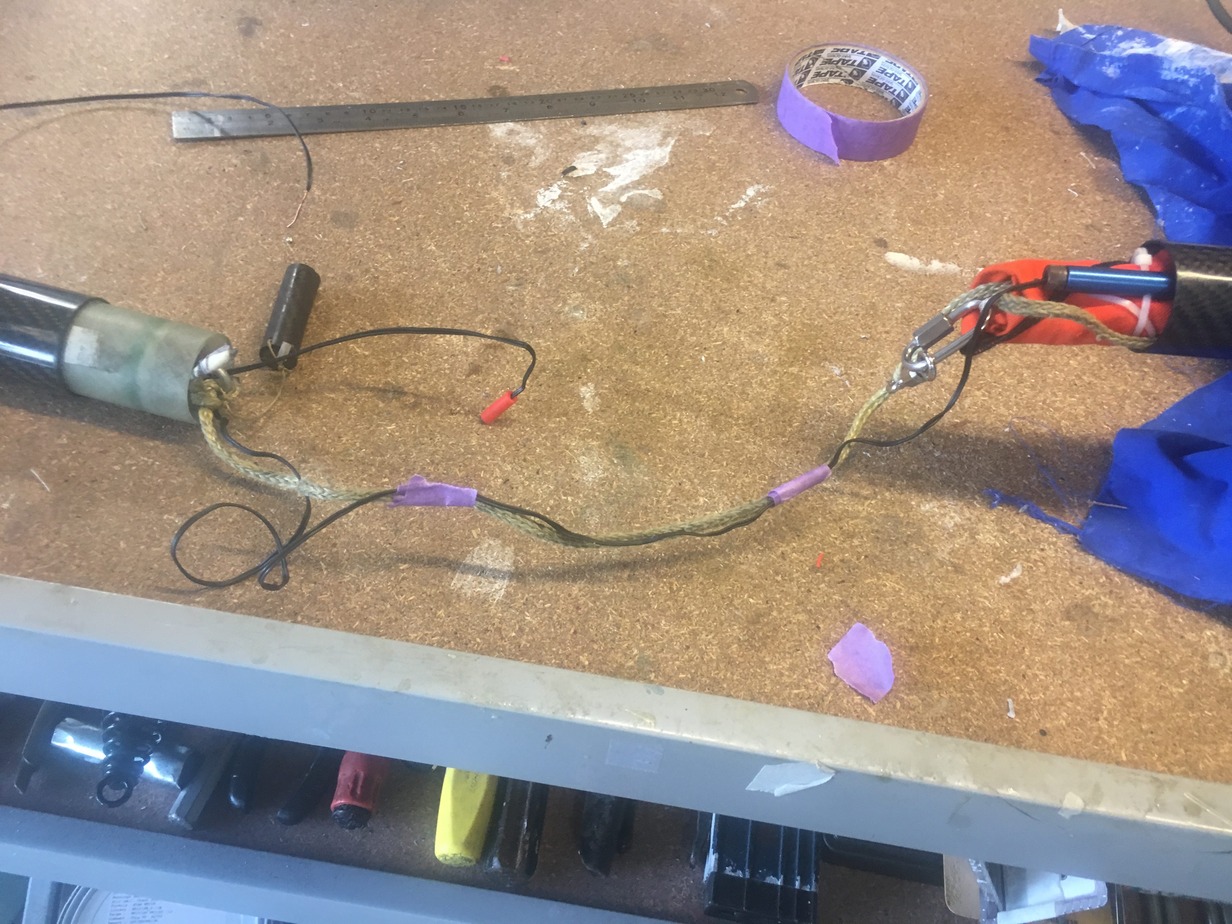
Determining any potential issues with igniters/charge well/shock cord.
3rd Test: Tape igniter cable to shock cord, at two points with painting tape. Just trying to keep things orderly.
3rd Test: Packing parachute bundle into air-frame.


Results of the Ejection Test

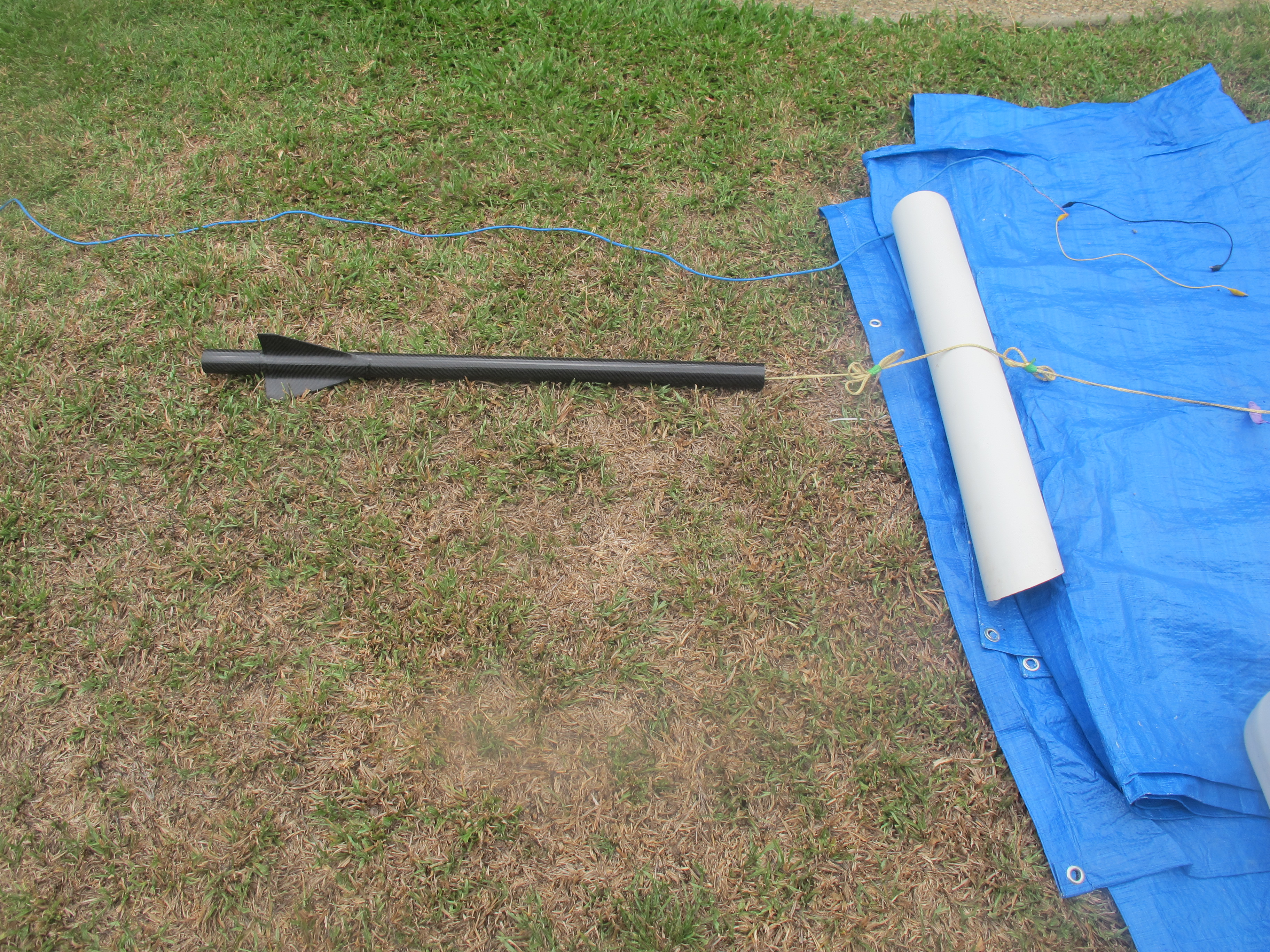
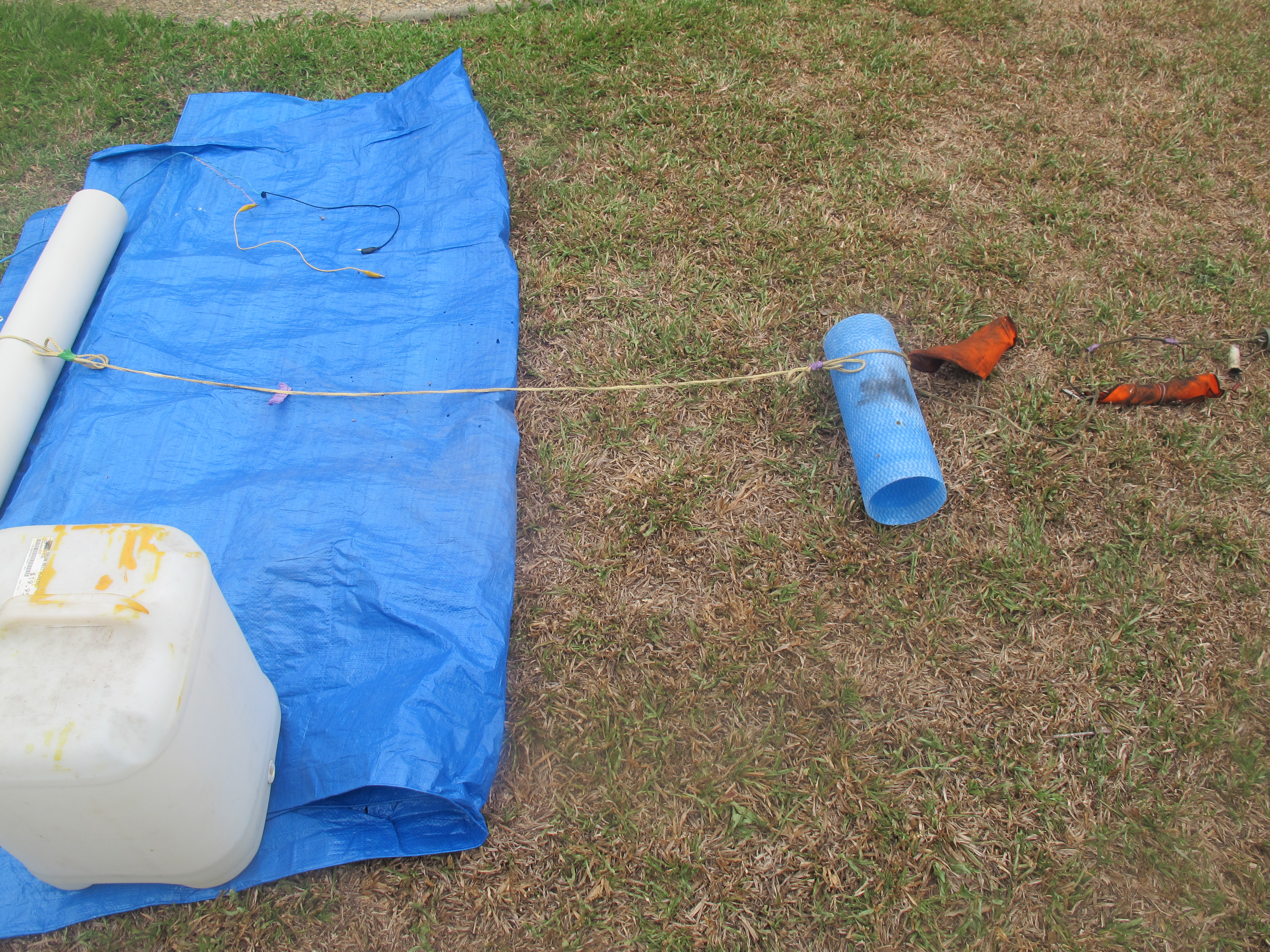
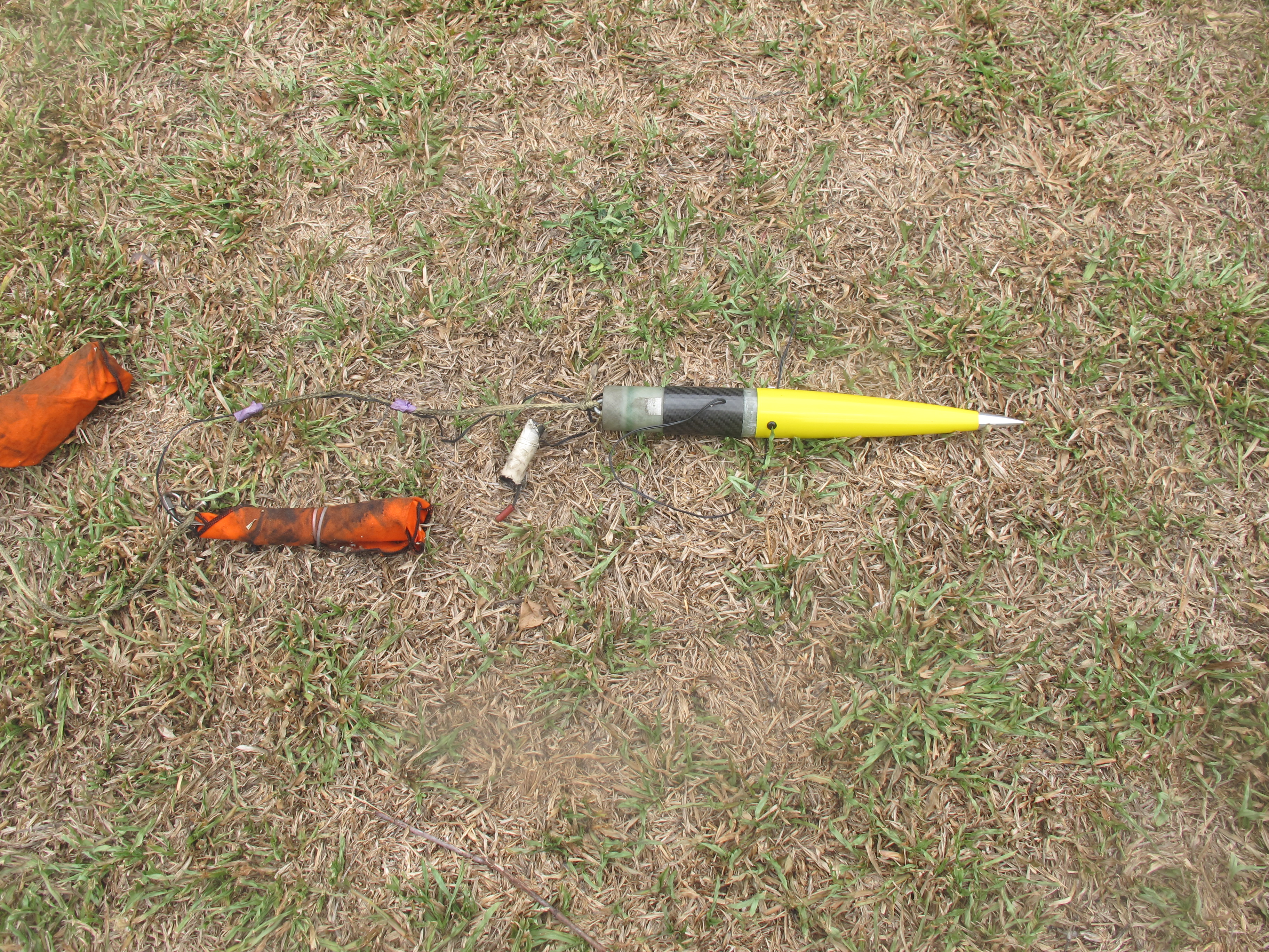
After the test we observed:-

  • No tangles. Great!
  • One of the Z-folds opened up, two left to open up (This is good). The reason this is good is because we expect the load to be “fairly” significant when the parachute inflates and these Z-folds will help reduce load on the rocket components.
  • There was no damage to any component (though the charge well is showing some wear after three tests. It is still in good enough condition for use in launches.
  • The Cable Cutter still attached to the parachute
  • The e-match wiring in-tact


Here are some photos and a movie.
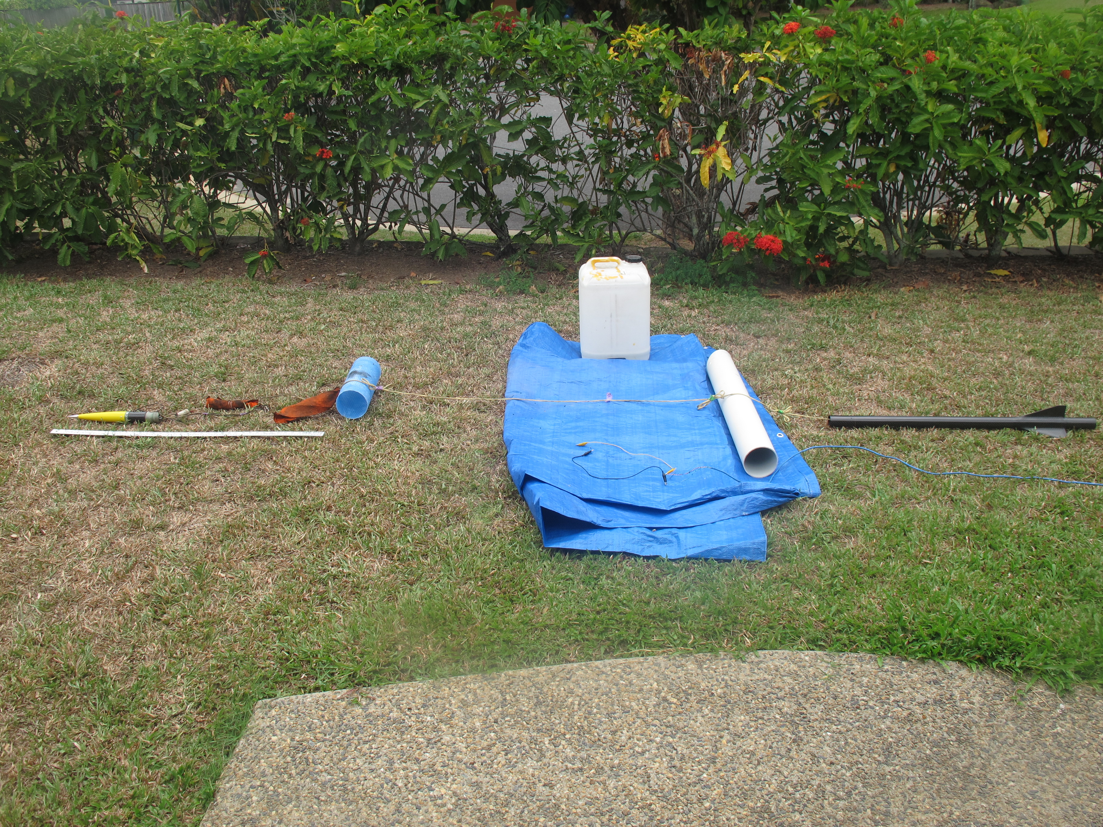


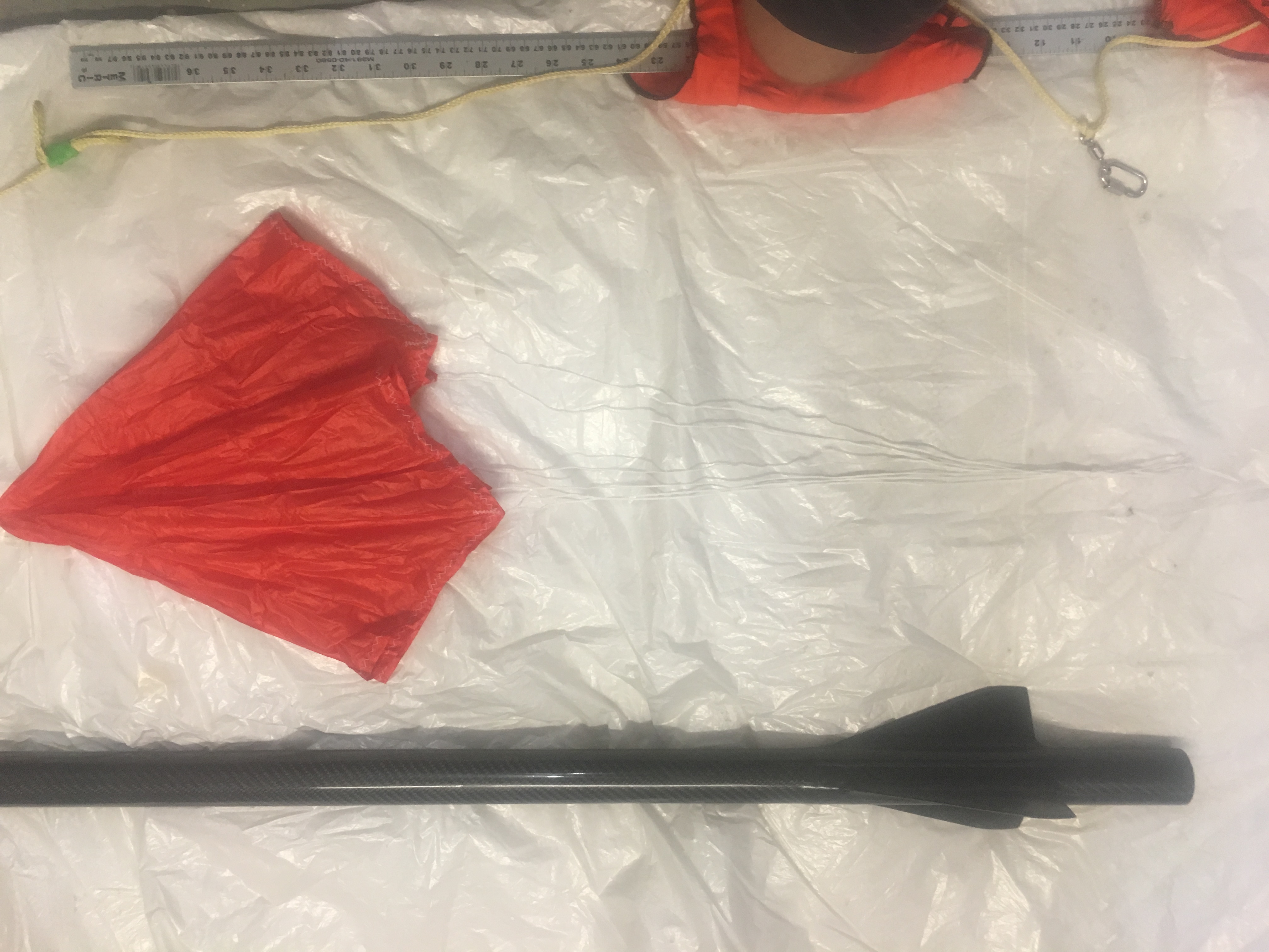
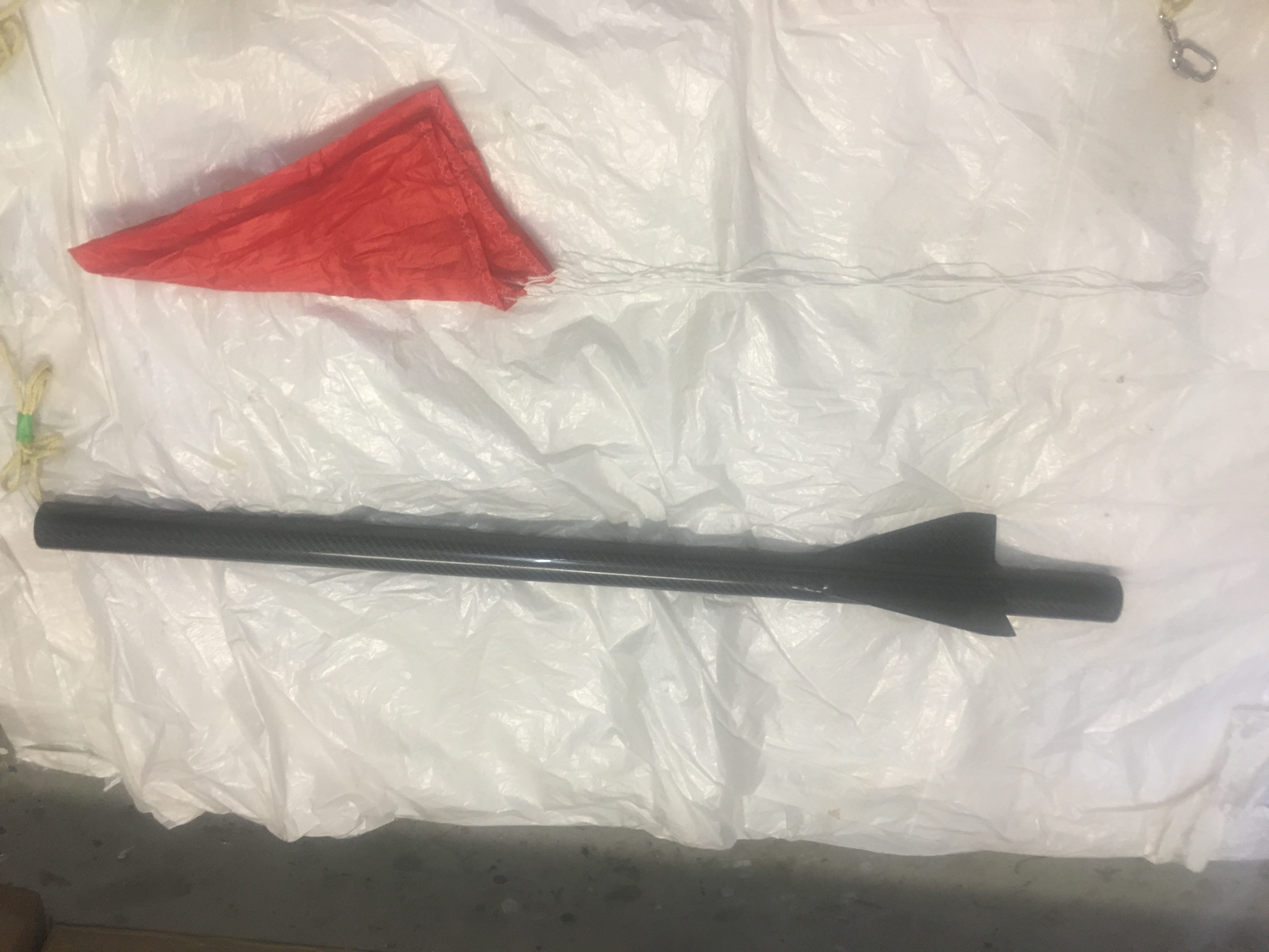
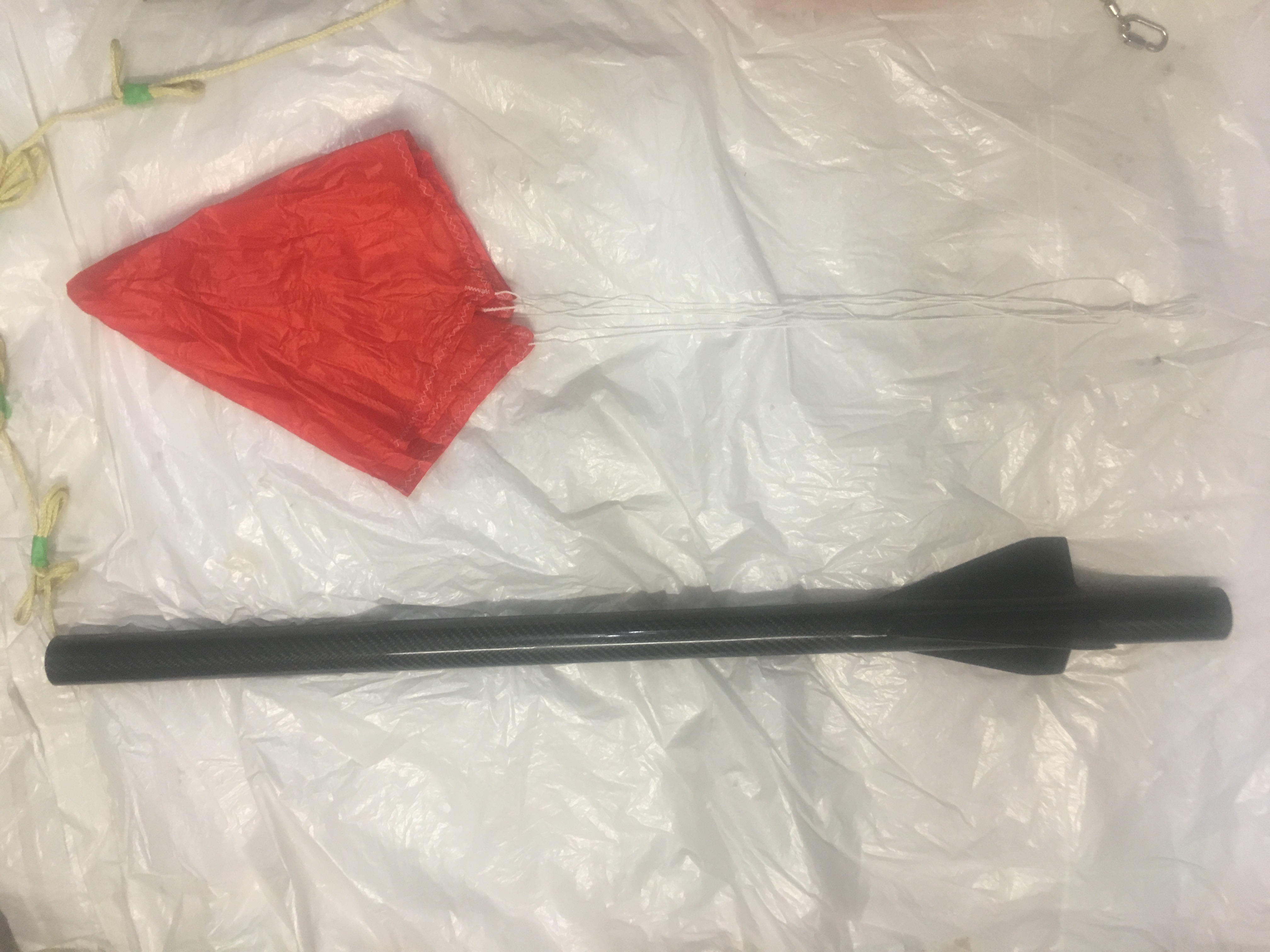
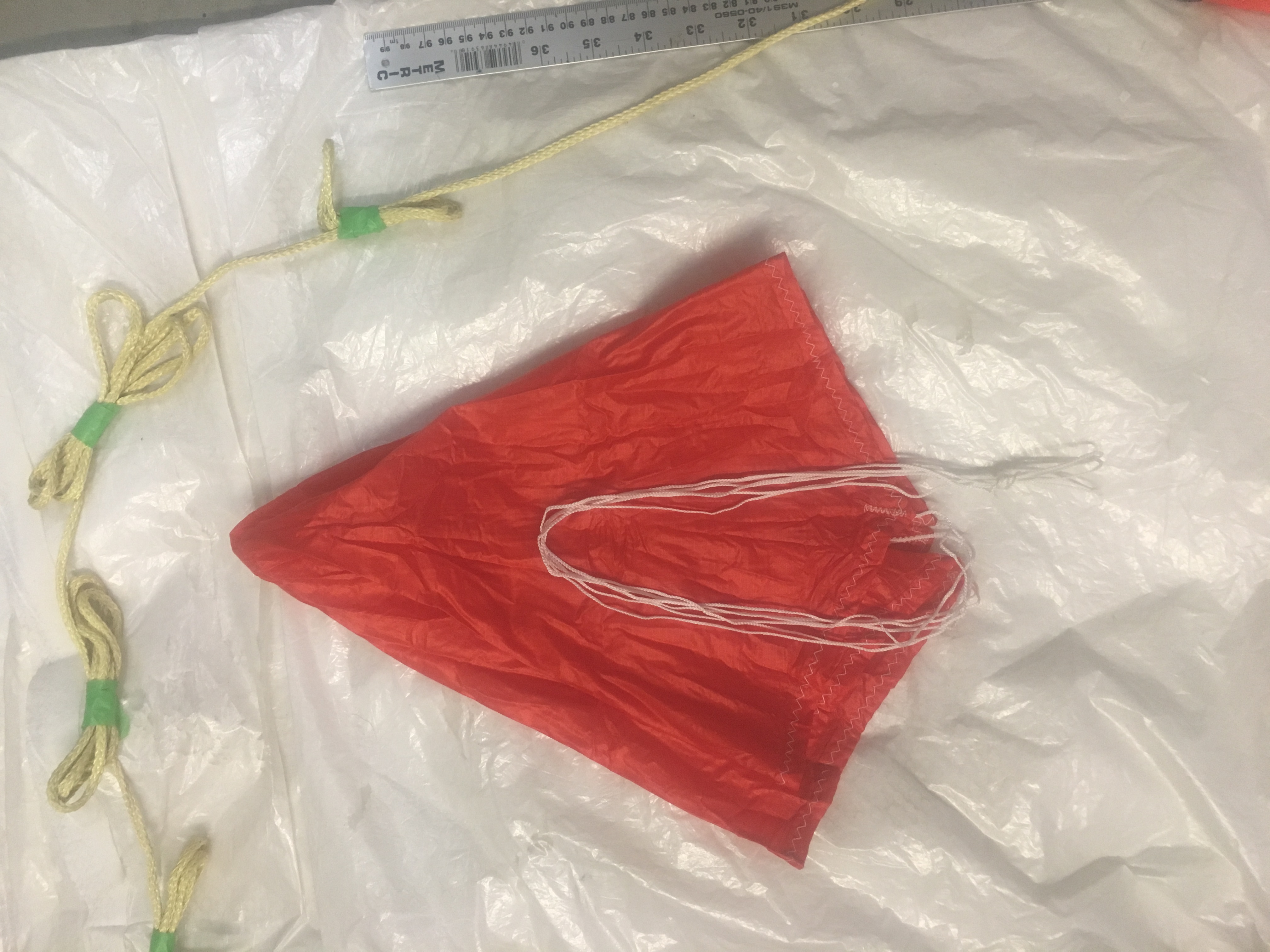
Showing off parts after ejection - side view. Take note of ruler.
Showing off parts after ejection – side view. Take note of ruler.
Inspection reveals no issues.
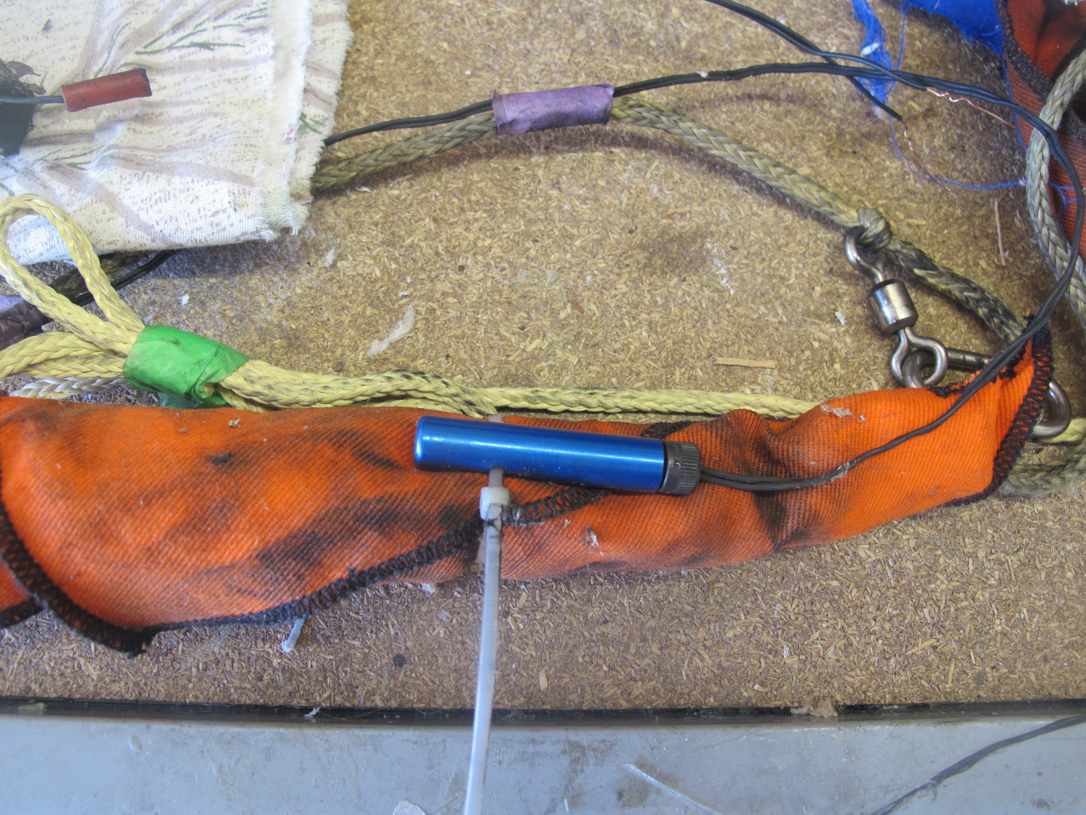
Inspection of nose cone end reveals no damage and cable cutter igniter intact. No tangles.
Inspecting Cable Cutter and parachute/Nomex blanket. Seems to be intact.
Inspecting parachute - no damage.
Inspecting parachute – no damage.

Rocket Radio Tracker

I decided to create a radio tracker for this rocket as I expect that it to travel quite far and high when it has the “real” large motors installed in it.

The Parts List

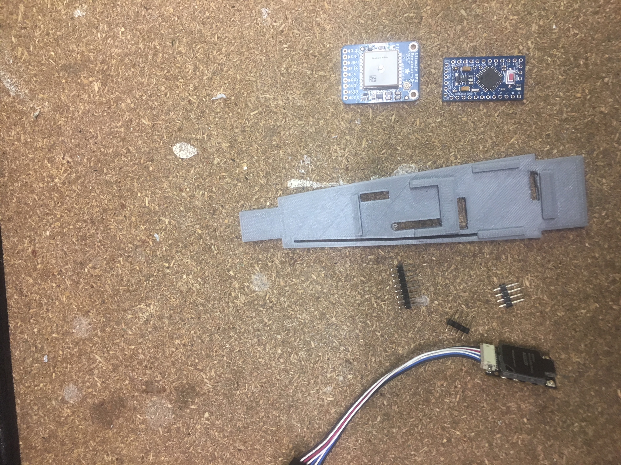
  • Arduino Pro Mini – 5 volt version
  • RFD900u modem
  • AdaFruit Ultimate GPS
  • 3 Amp/5 volt UBEC
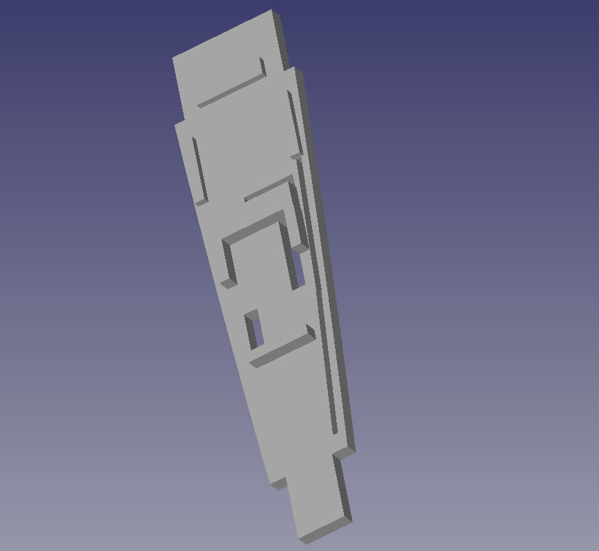
  • 3-D printed “tray” to fit into the nose cone
  • VeraboardĀ  + header pins + wire
  • 2 x 240mA LIPO batteries

The Design

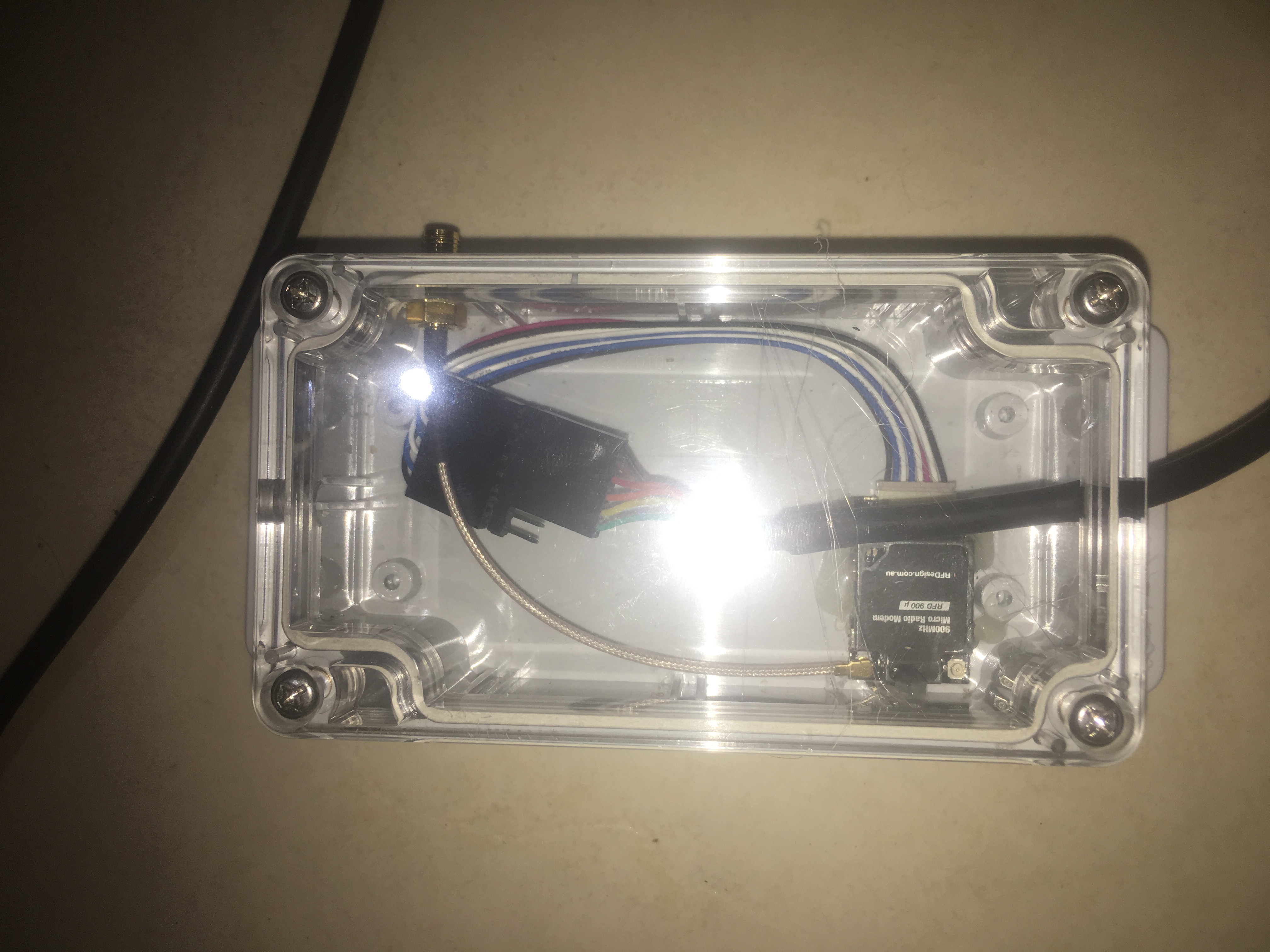
The RFD900u modem

I connect the RFD900U modem on the rocket end to the Arduino – pins 4,5 and use Software Serial. I power the modem directly off the 5 volts from the UBEC as the power requirements of the RFD900u modem can exceed the maximum current the Arduino can supply.

I’ve loaded the modem with latest version of firmware 1.13 and after setting to the default settings I changed:-

  • ECC to on
  • TXPower to 17

I set the TXPower to 17 because life of the batteries is a big factor and 20 will suck the batteries dry. Tests have shown that every minute of operation, the batteries drop by 0.01 volts. So if the starting voltage is 8.30 volts and the final finish voltage is 7.5 volts, then we are looking at about 80 mins of operation. This is fine.

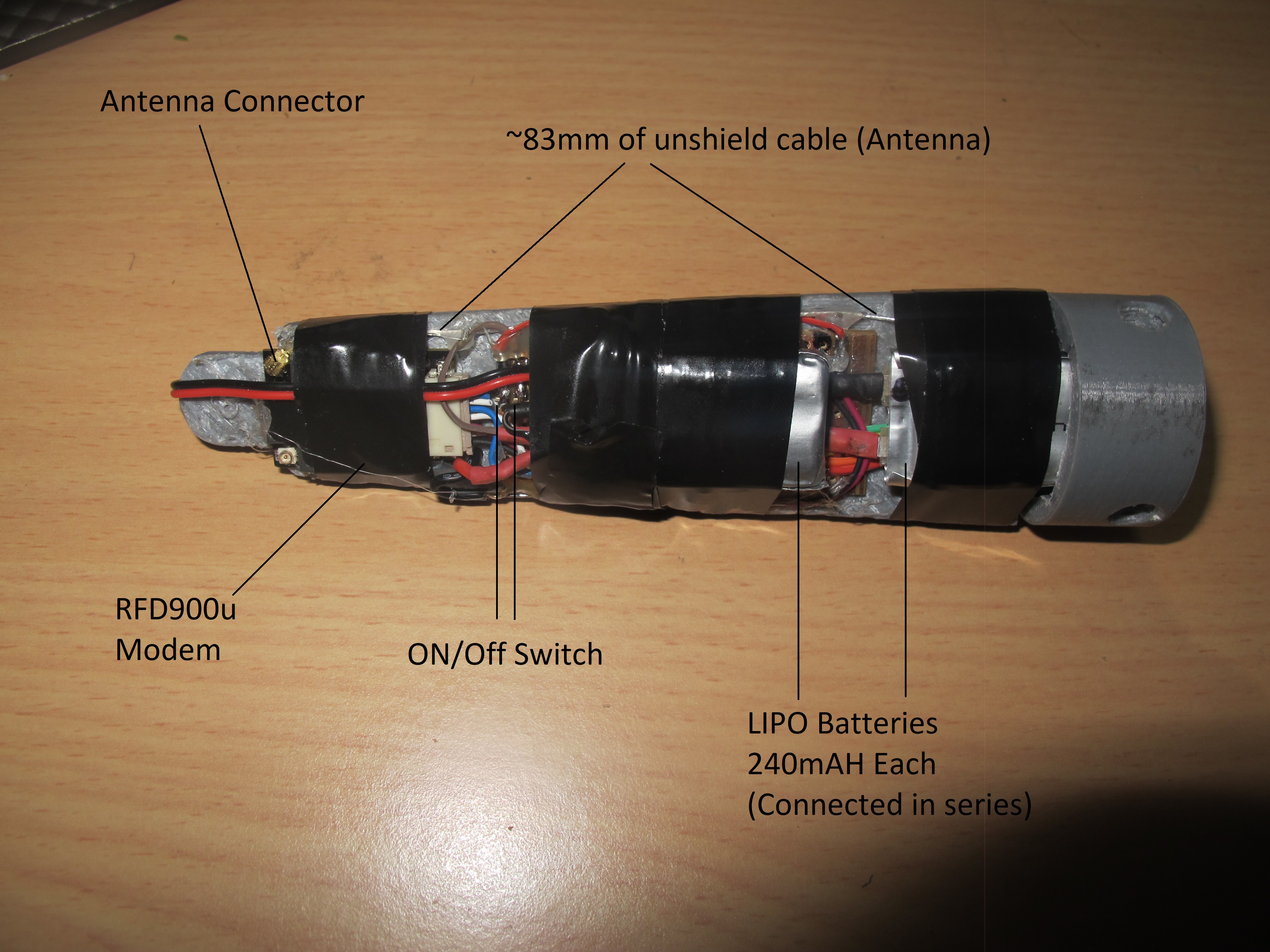
One of the issues I had was working out the antenna side of things. There is just not enough space to cram a 1/2 dipole antenna. So I have to go for a 1/4 dipole antenna. unfortunately, there really isn’t enough space for this either!! So I converted a cable for connecting an antenna INTO the antenna!

The Ultimate GPS

This device is connected to pins 2, 3. It chews about 20mA of power and is also powered directly from UBEC.

I’ve written the Arduino program to log GPS points to the internal logging area. Unfortunately, it only logs it every 15 seconds. That will have to do.

The Arduino Controller

There isn’t much to this. I choose to use a 5-volt version because all devices I’m connecting to it can operate at 5 volts. This controller doesn’t have much work to do. All it needs to do is read GPS data and send it to the Receiver via the RFD900u.

The mounting tray

I wanted to mount this inside the fibre-glass nose cone. This was quite tricky because of the limited space. One thing I wanted was for the tray to follow the contours of the inside of the nose cone. i.e. rub up against it. This will provide some stability in flight. It will also maximise area for mounting the components.

Construction

Here are some photos:-


Screen grab from FreeCad.
All parts out ready for assembly.
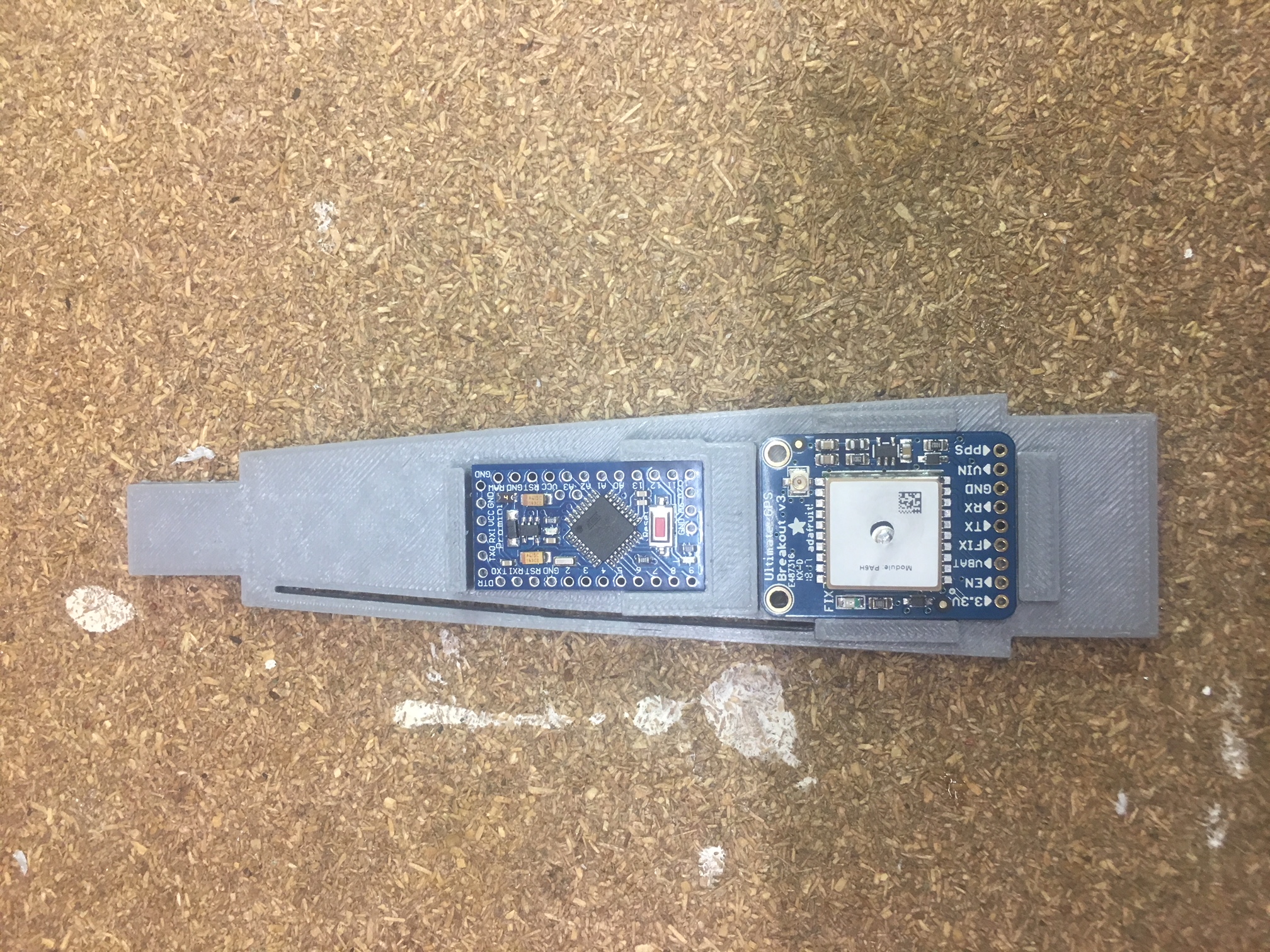
Electronics Breakout Board side


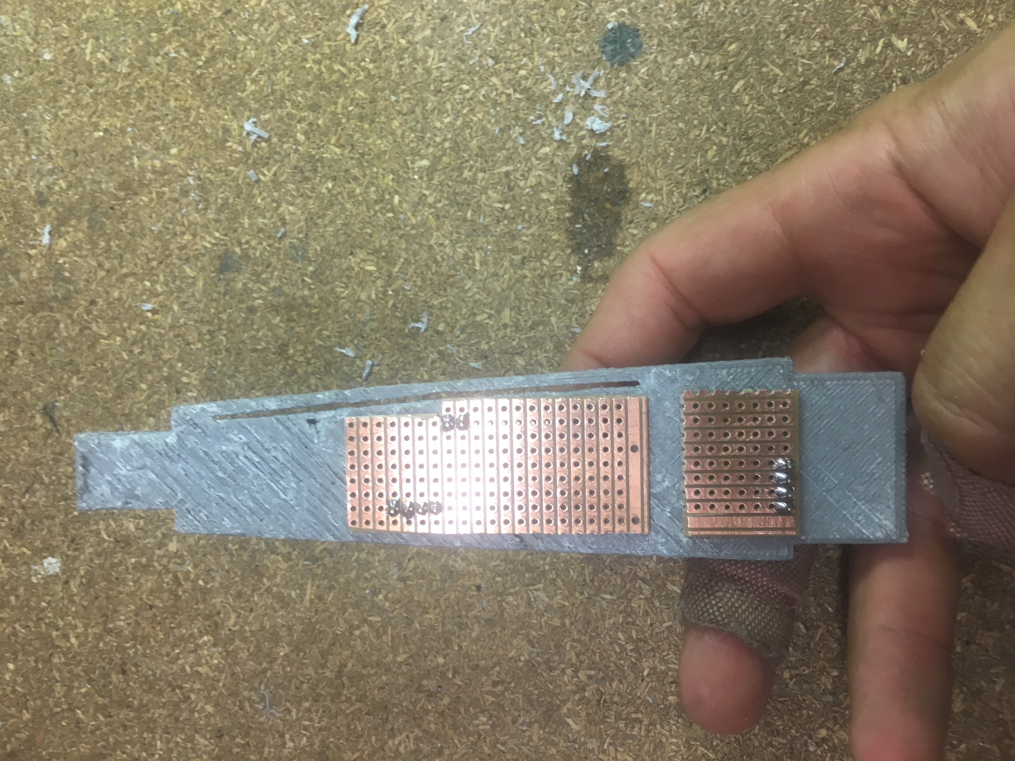
Vera board side.
Vera board side.
Assembled in cylinder section that slides into the coupler.

I dislike Hot-Glue, but It came in handy for attaching:-

  • RFD900U modem
  • 2 x LIPO batteries
  • Keeping wires “safe”
  • Ensuring GPS and Arduino module can’t pop out.

People at AusRocketry forum recommended some tape to ensure that the modem doesn’t rattle off. This sounds like a wise idea.

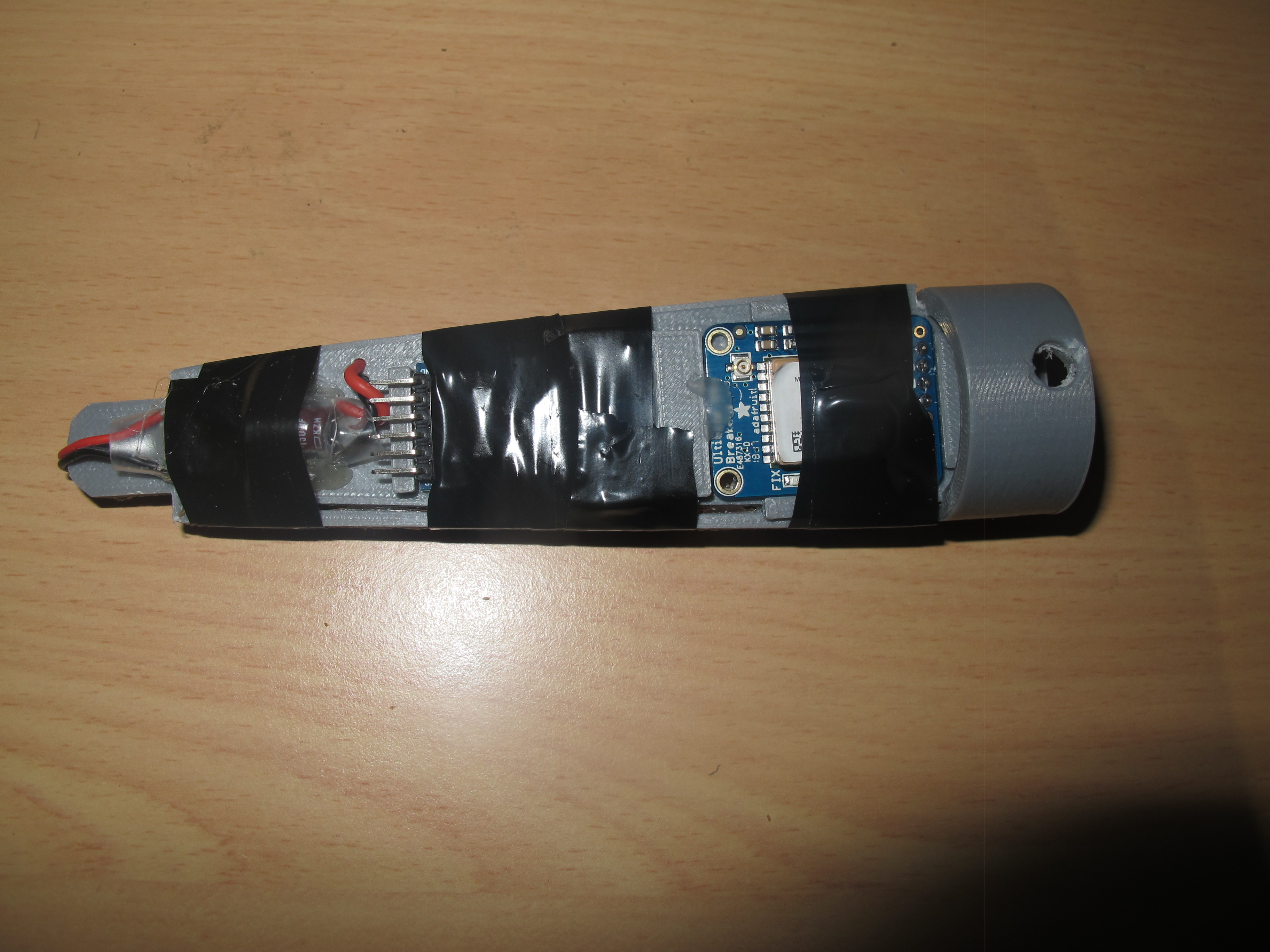
Break-out board side.
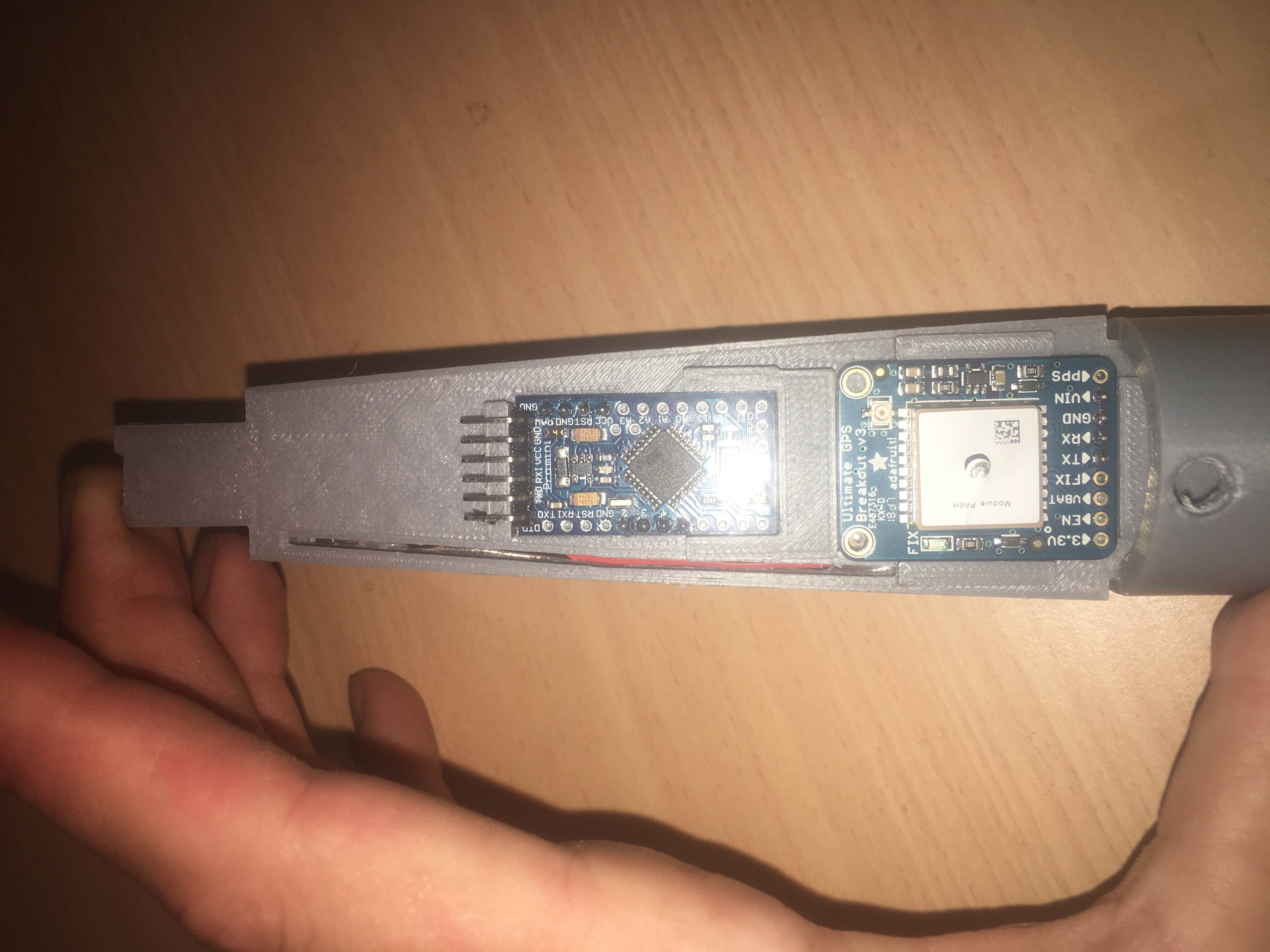
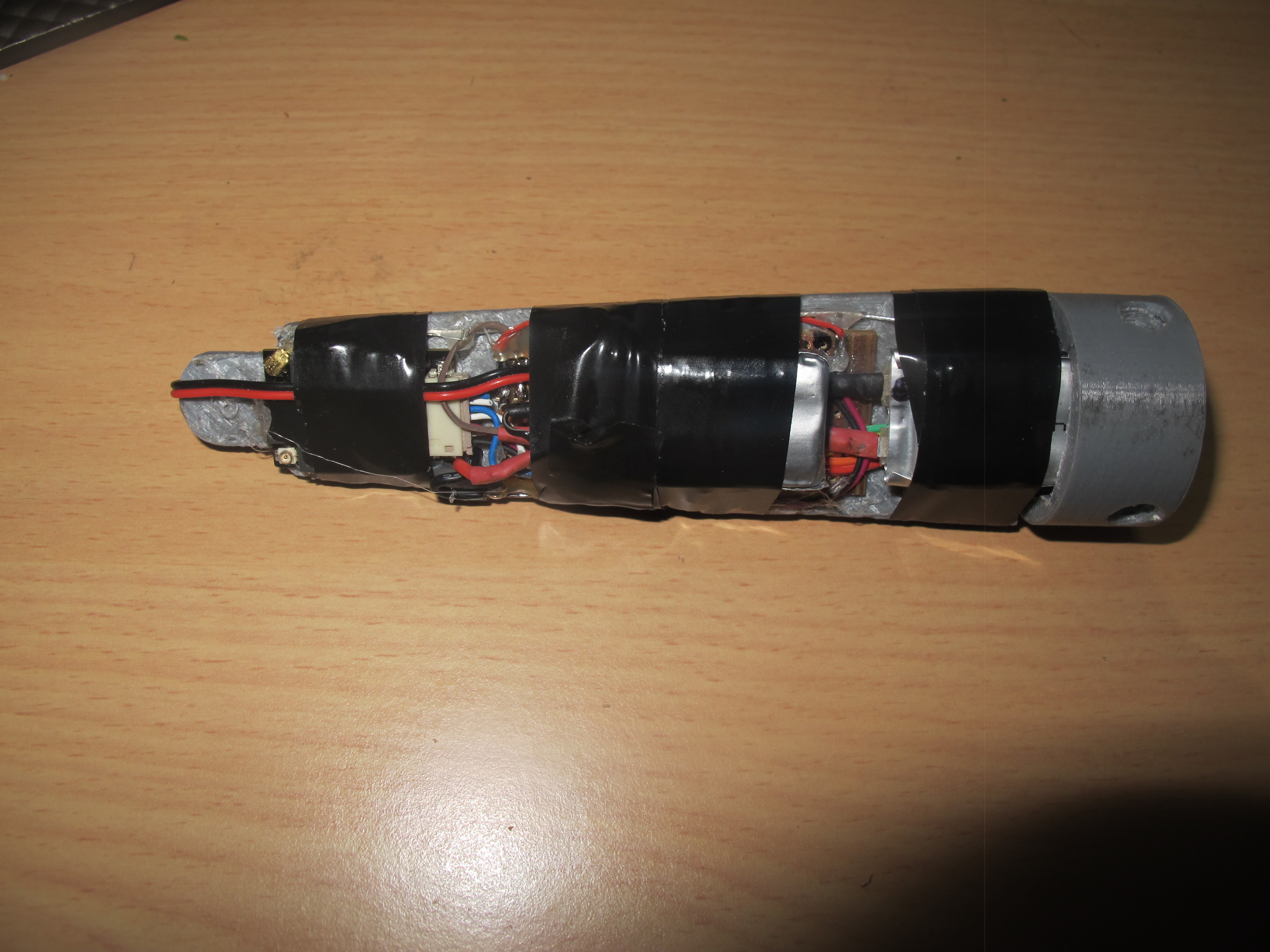
Wiring side of Tracker Payload.

See the photo below showing the various parts of the tracker.

Various parts in the tracker.

The Ground Station

Sole RFD900U modem unit for connection to computer.
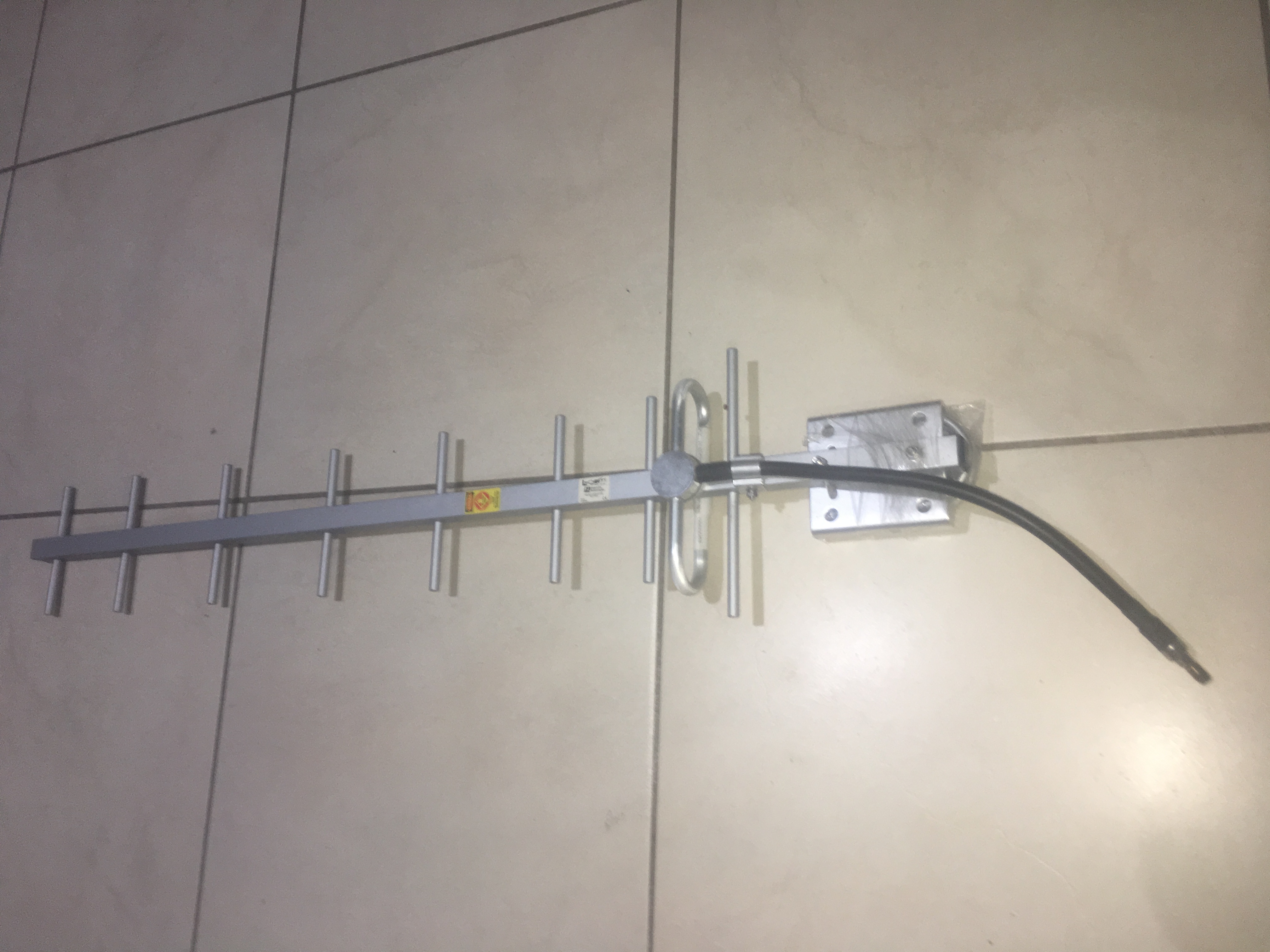
900MHz Yagi Antenna
900MHz Yagi Antenna

Range Testing

I reduced the power on both modems from TxPower = 20 to TxPower = 5. Then I did some tests about 100metres away. I still got RSSI of about 120, which isn’t too bad, considering it is low power.

I estimate it should be able to do about 2km no problems with this configuration; with optimal environment i.e. LOS and plenty of clearance. Probably able to get a few more km in ideal circumstances.

Testing the Cable Cutter

The Cable Cutter

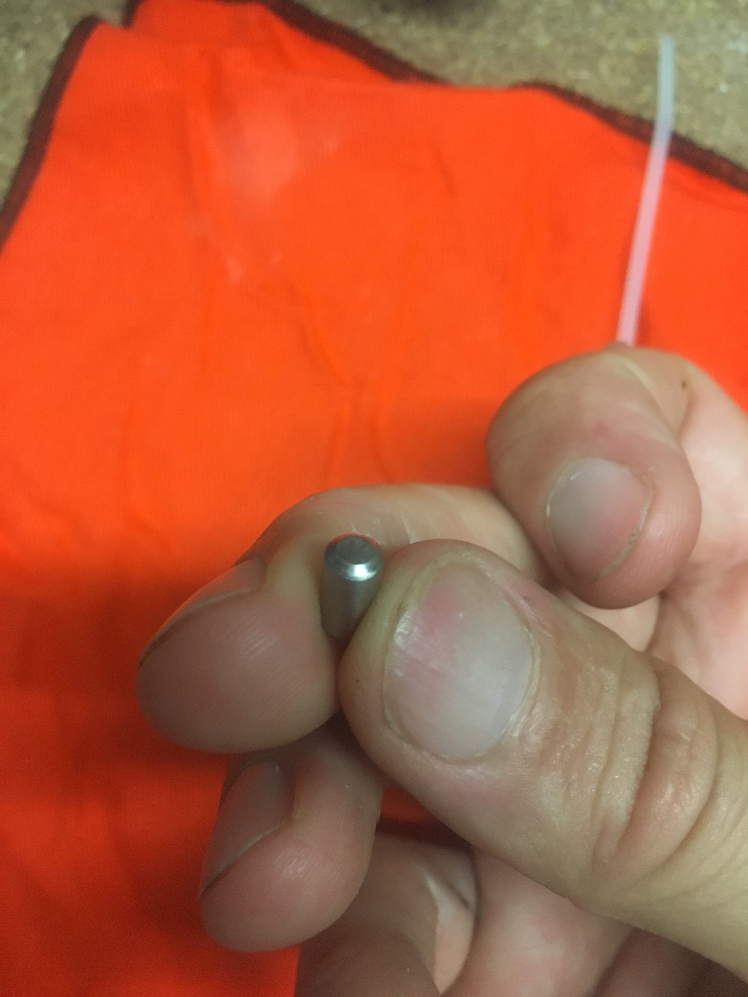
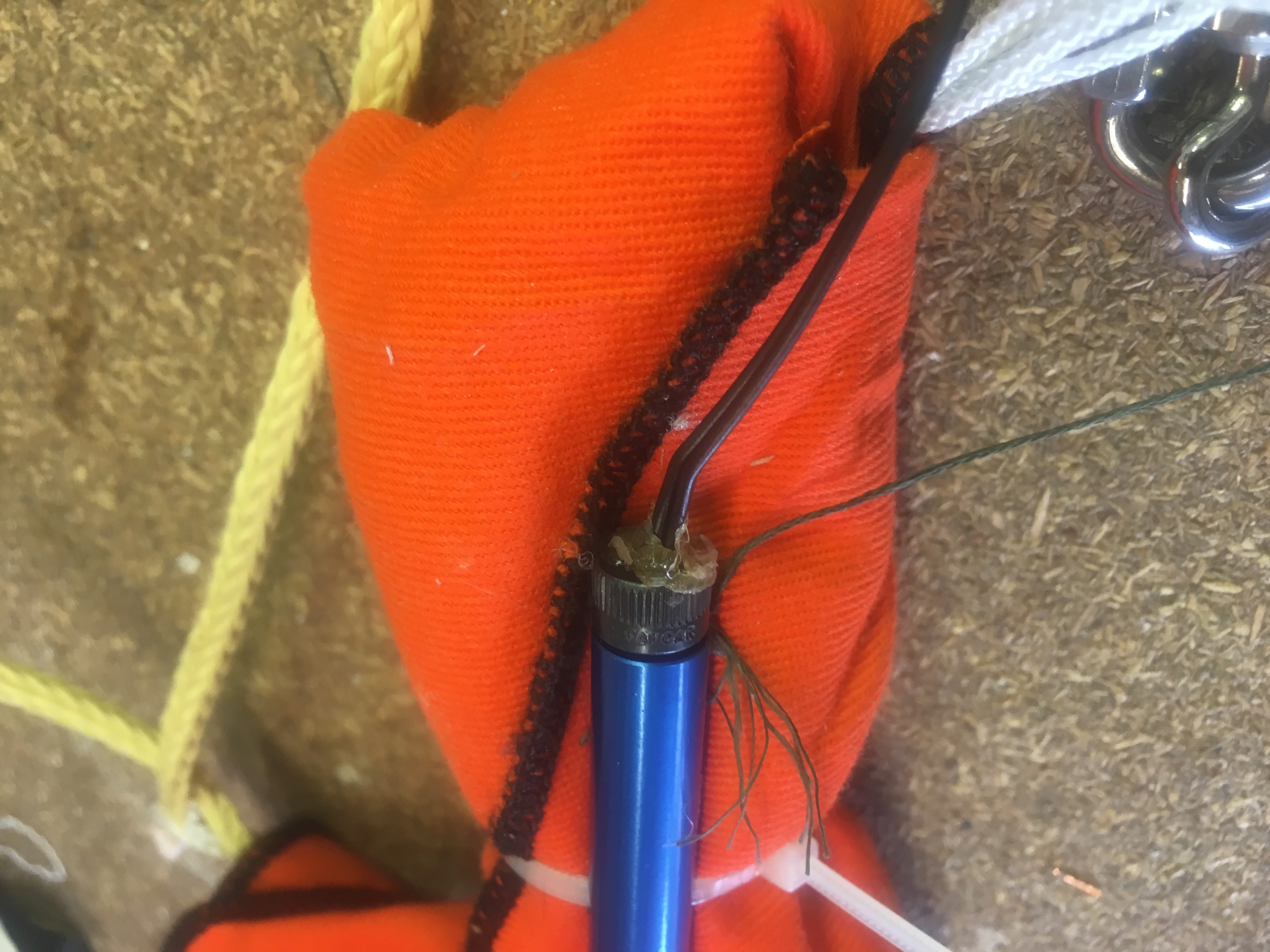
The Cable Cutter I purchased from Aerocon Systems has cambered edges as shown in photo below.

This should have a very sharp cutting edge...a concave hole.
This should have a very sharp cutting edge…a concave hole.

According the supplier, this is normal of these cutters now and is on purpose because the Aluminum cartridge gets damaged from the sharp edge of the piston when too much Black Powder is inserted.

Creating a Cutting Edge

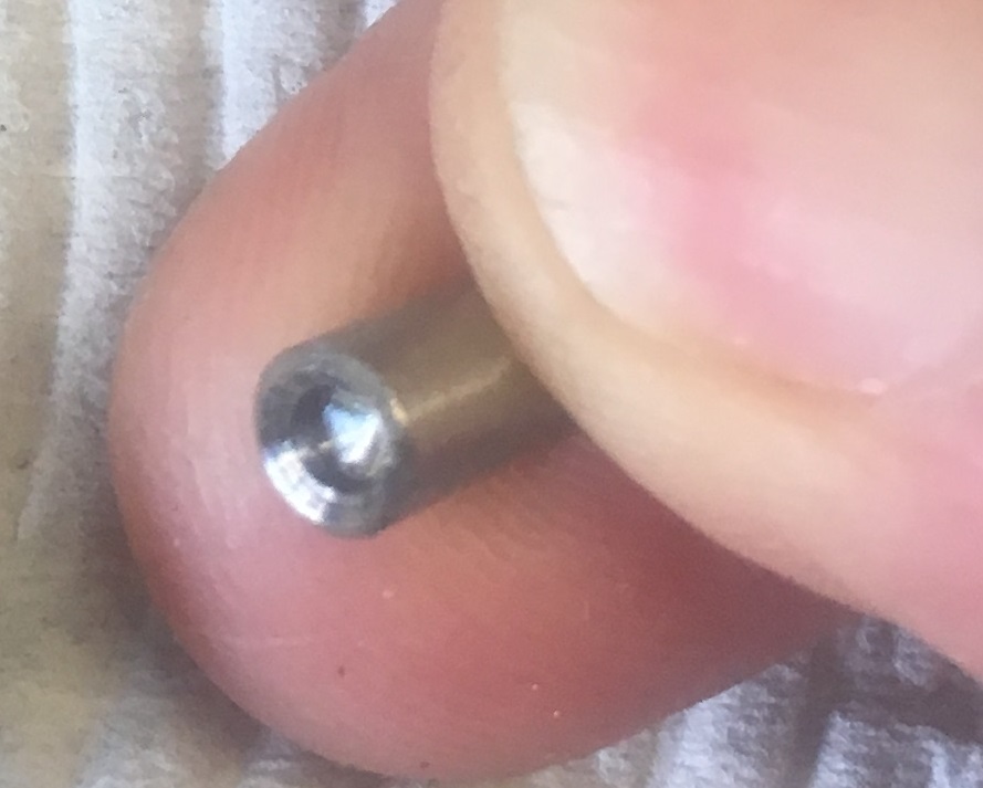
I decided that I would introduce some sharp edges because it just didn’t cut on my first test; and if it doesn’t cut the cable tie, it is of no use to me. So I drilled about 3mm into each end with a 2.5mm drill bit. Then I used a counter-sink bit to create a bit of a ‘crater’ with a sharp edge. See photo below.


3mm deep hole drilled with 2.5mm drill bit.

Precise steps were:-

I did this in the vice, very carefully using Aluminum brackets to not distort the steel piston. I marked the center point using pencil under magi light. Then I used punch to mark the center.

I went straight to the 2.5mm drill – special tip and used cutting fluid. It drilled just fine. Then after drilling to a depth ~3mm I used a countersink drill bit to go about 1mm in, to get a “cutting edge” just inside the main diameter.


Assembly

I assembled as follows:-

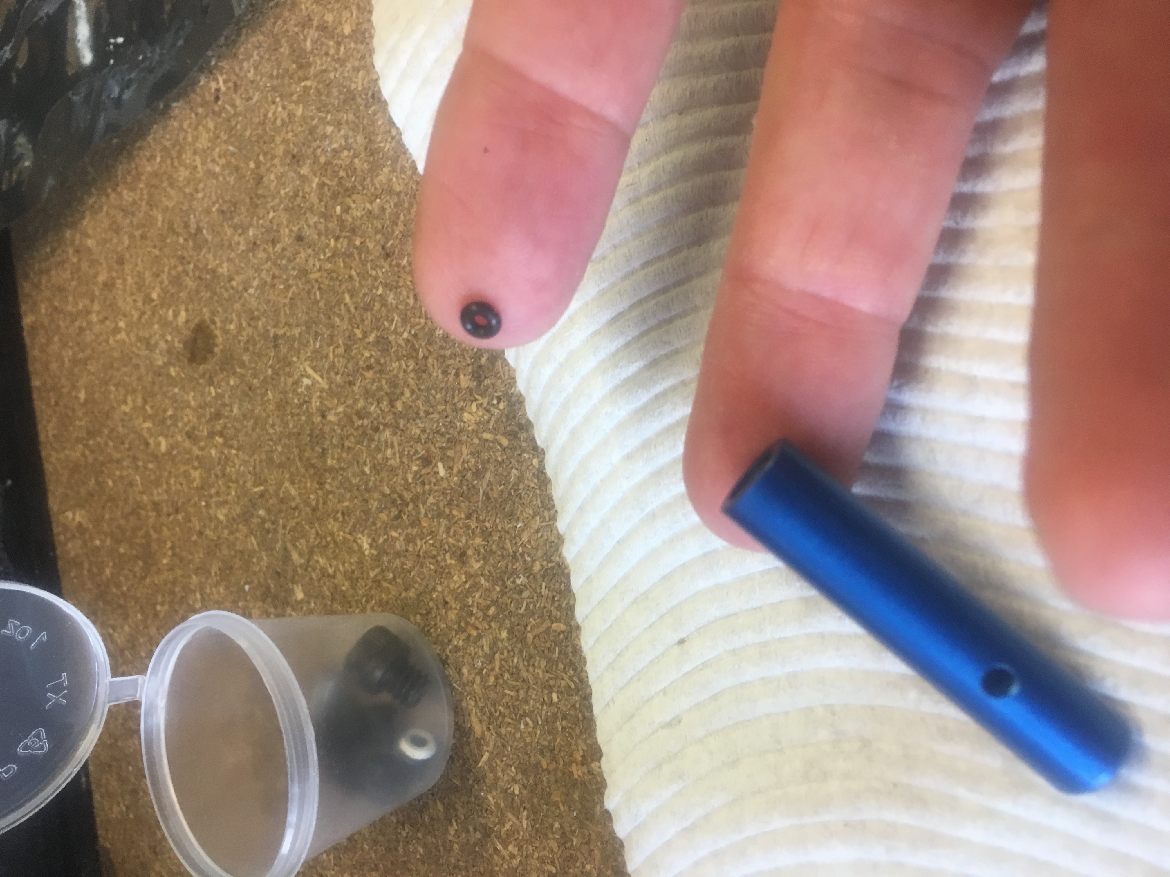
First goes the O-ring.


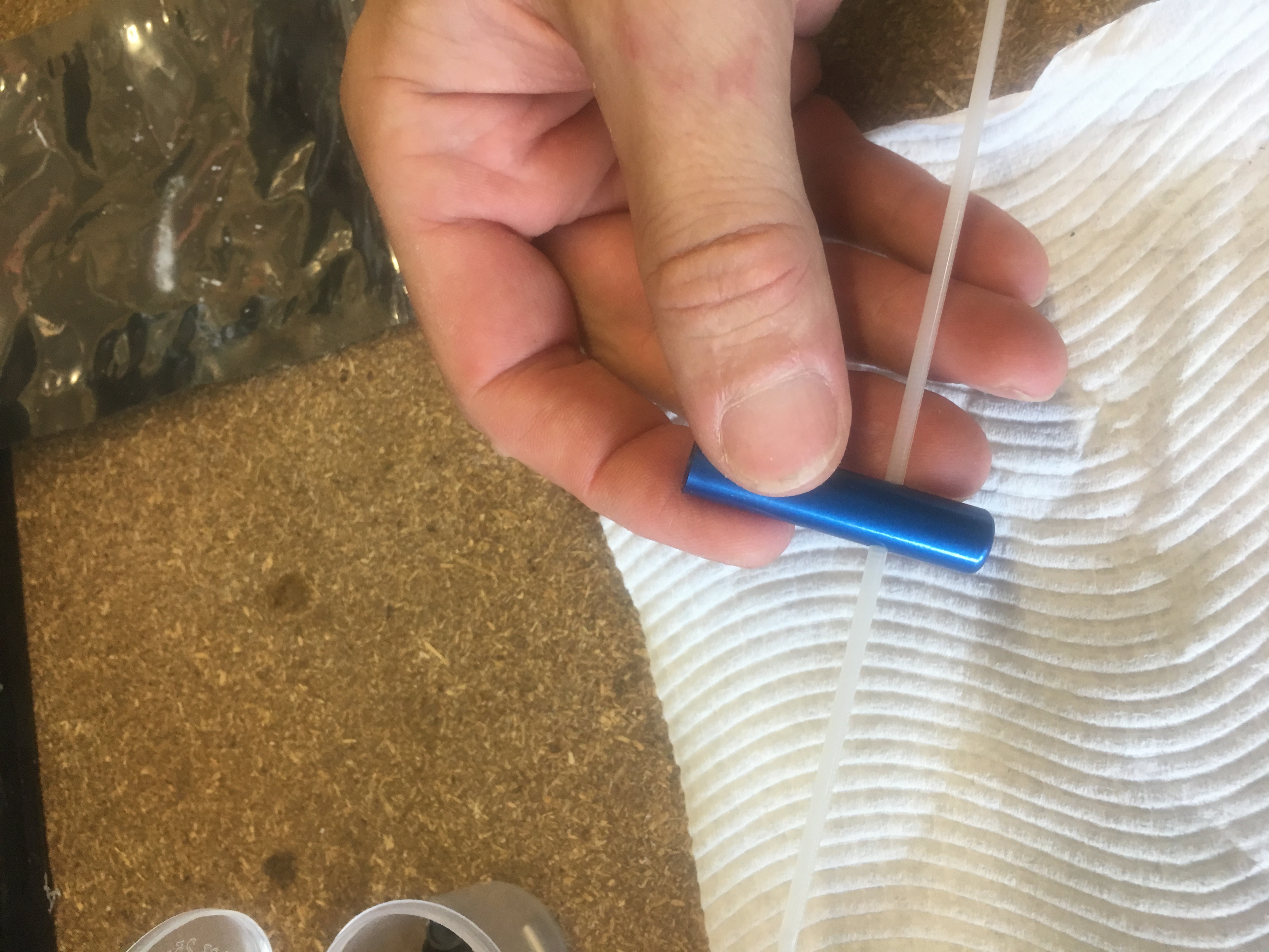
Threading the cable tie into the blue cylinder.
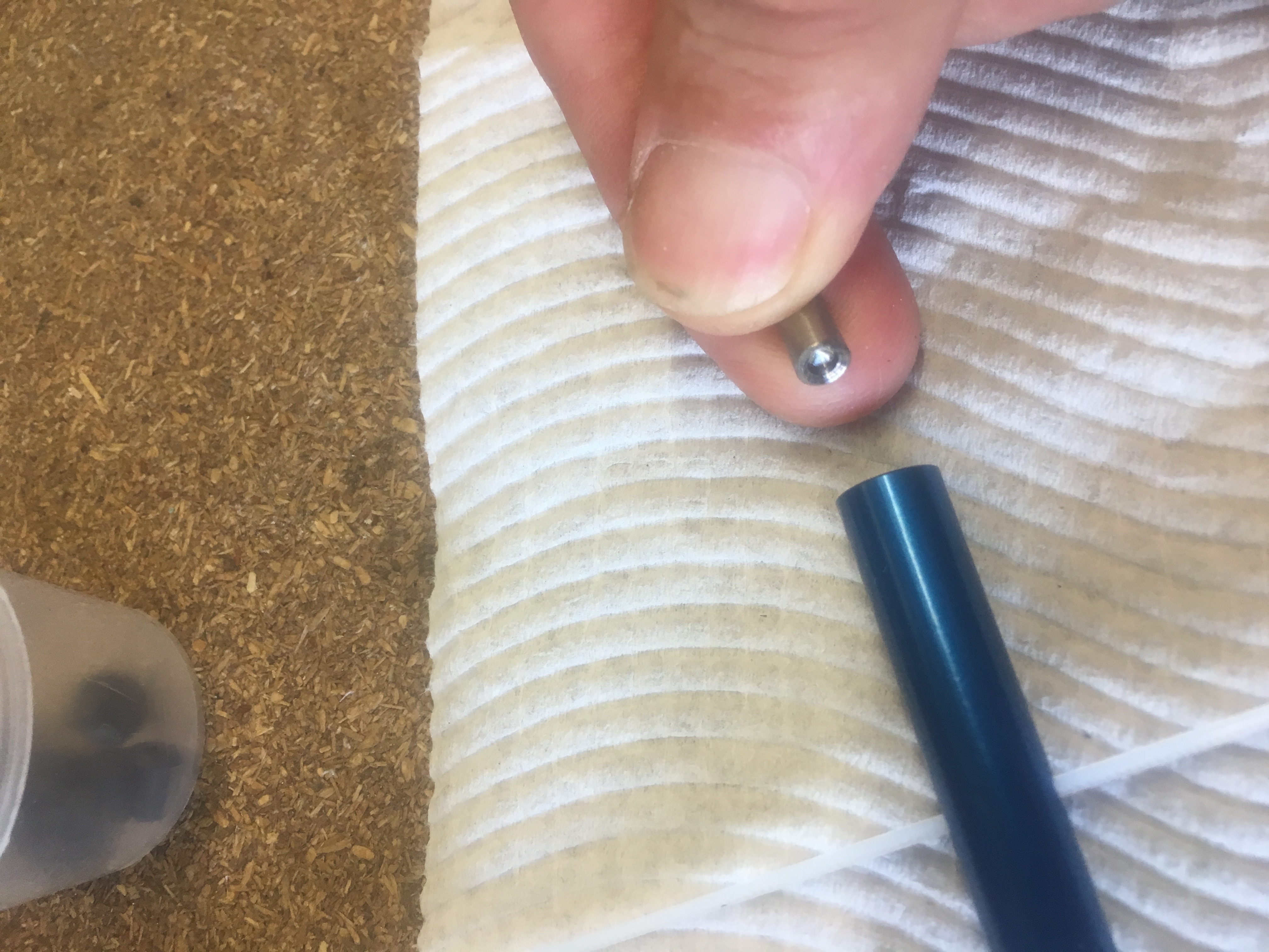
Slotting in the Piston.


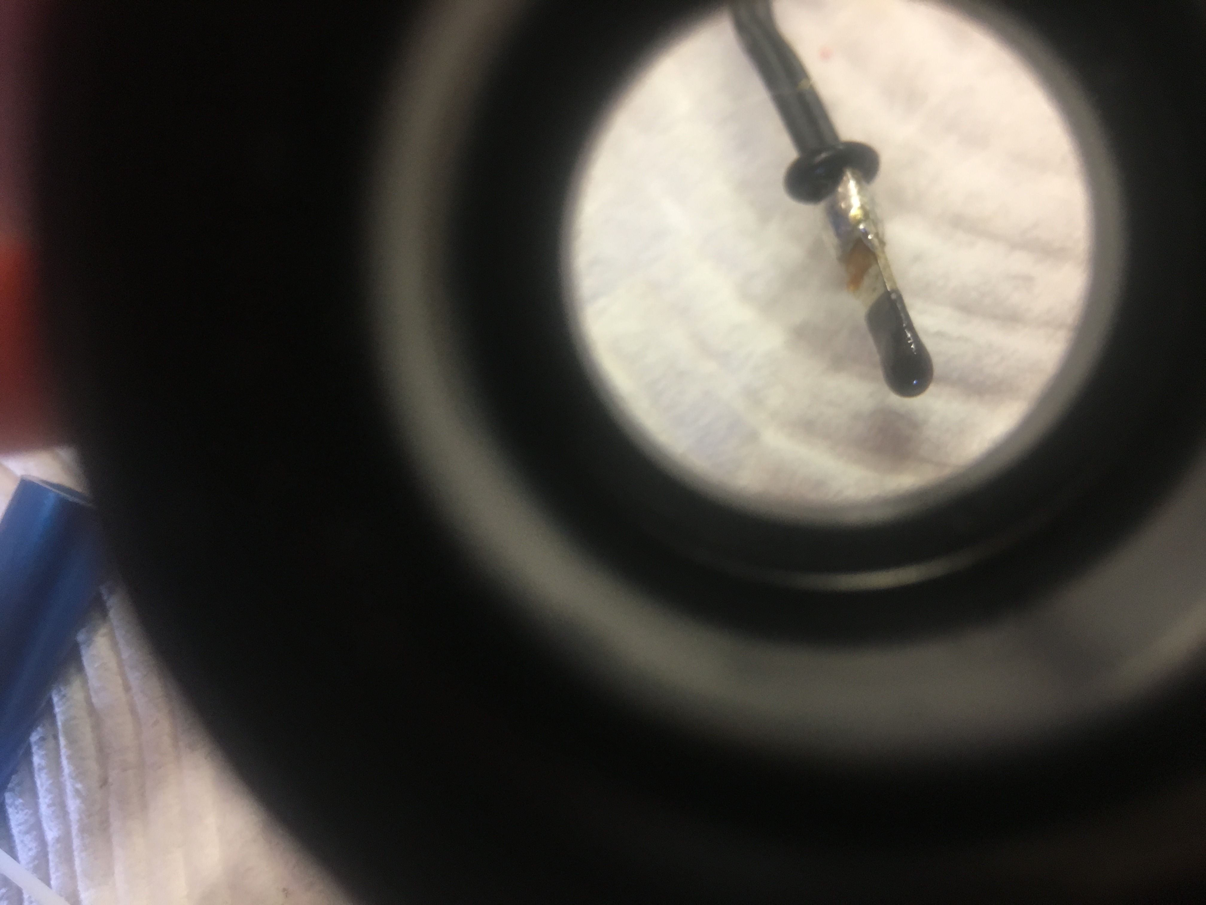
Next I straighted out the e-Match and took the red plastic protector off it. Then I rolled on a small O-ring. The O-ring has two functions:-

  1. To help seal the cylinder, reduce amount of gas coming out
  2. To stop shorting of the igniter contacts on the hex screw end bit.
Close up view showing the O-ring.
Everything fitted and plenty of hot glue melted on to end to ensure no gas comes out the rear.

I then melted some hot glue on the end.

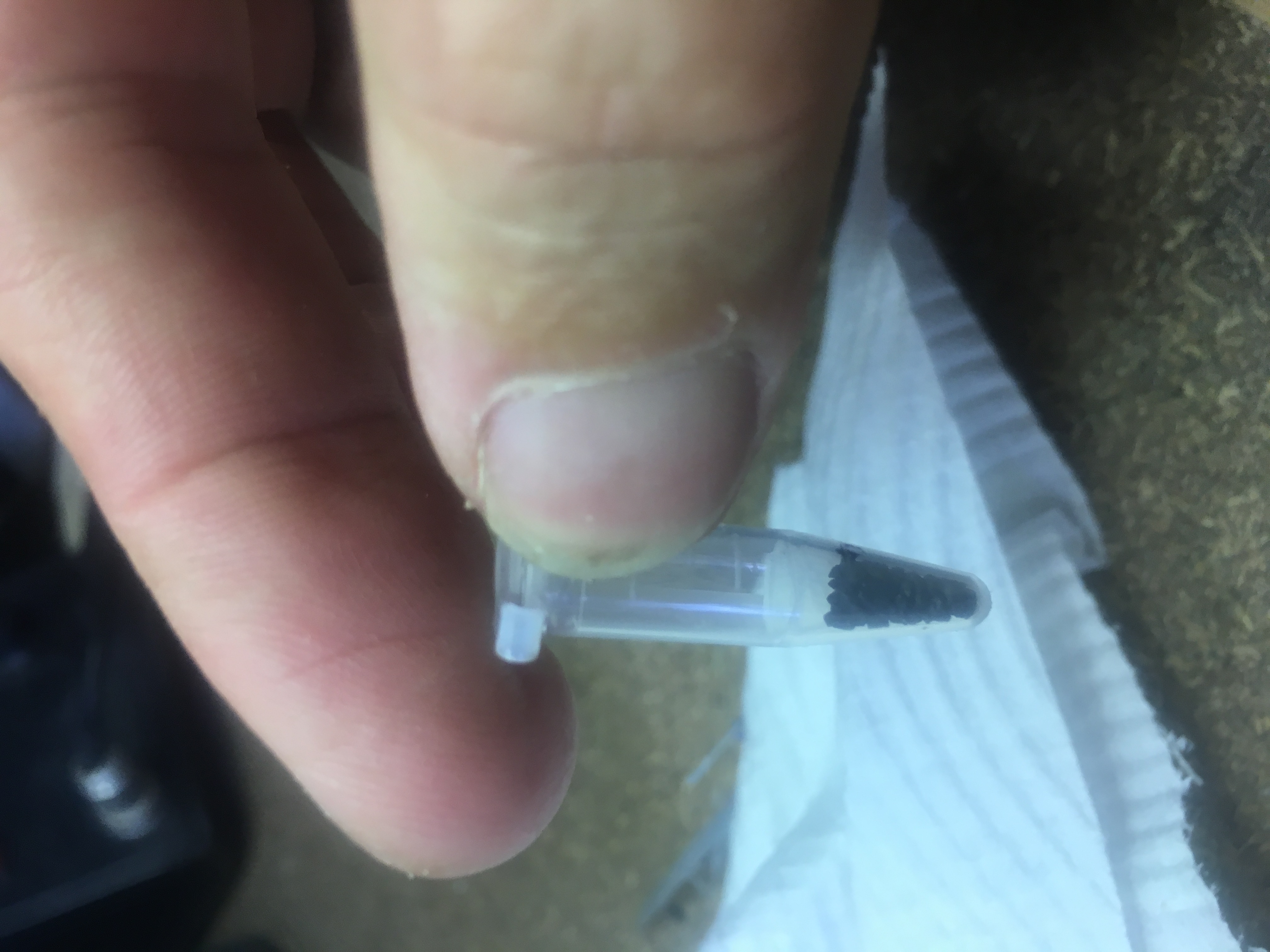
Then afterwards, I removed the screw bit…and put the measured 0.1 grams of black powder in.

0.1 grams of black powder measured.


Then I screwed it back together again.

The test

Below is a video of the test.


Very happy with it!