Gears and where they are used
We utilise XL sized gears for all axis :-
- The Spindle
- The Carriage
- The Filament delivery head
Issues experienced
We had severe issues with the gears/belt that moved the Carriage. We discovered that it was skipping steps and as a result the carriage would be ahead (or behind) where it should be.
Essentially, we had badly mounted gears at the stepper motor and at the idler end. The mis-alignment wouldn’t normally be a problem, but because of the large length of the Carriage belt, the engineering shortcomings were amplified.
A lot of this was due to my inexperience with gears, some due to badly machined gears. The main problem was mounting these gears on to motors and axles.
We got by in the end.
Carriage Stepper motor
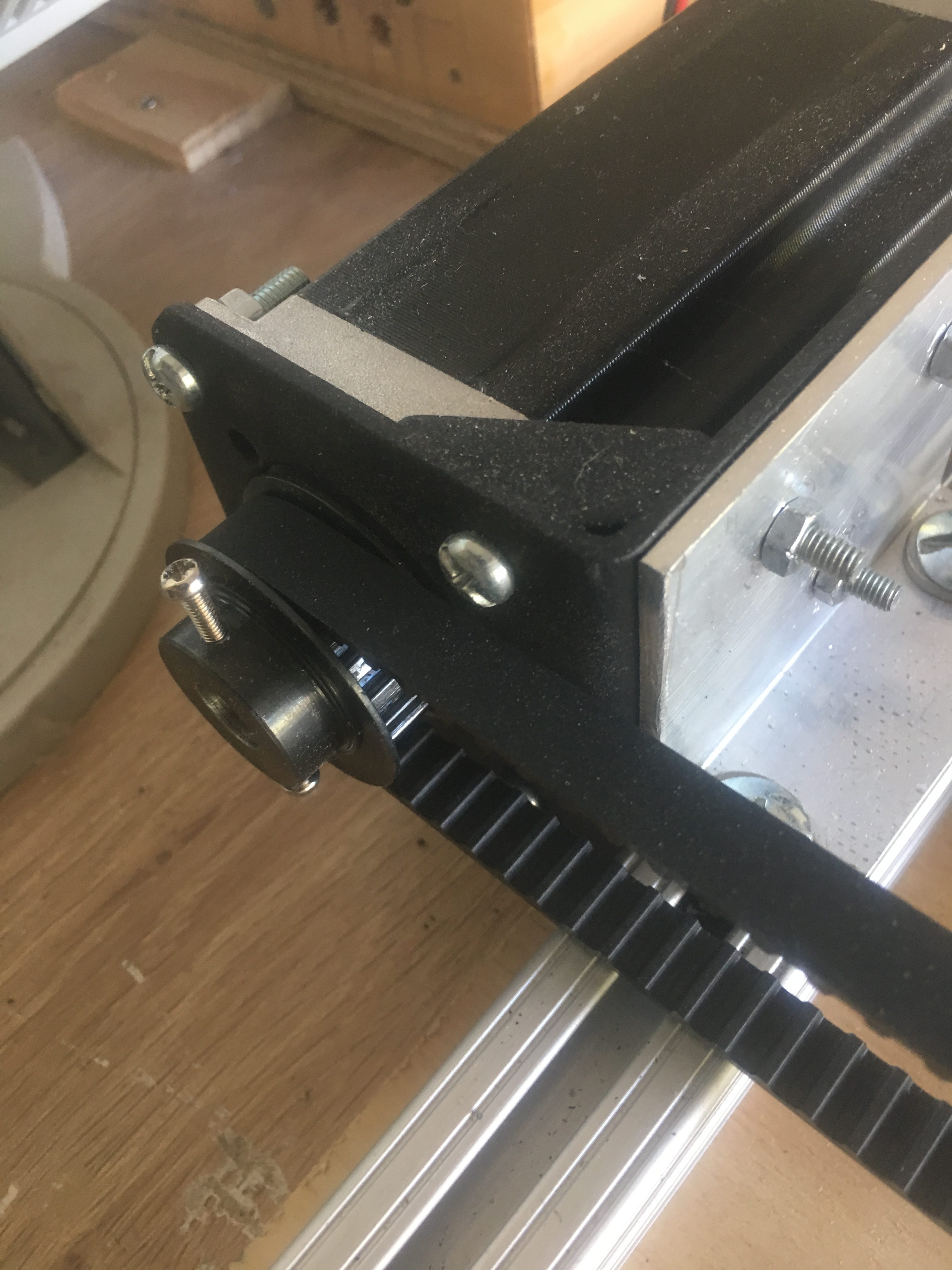
We eventually got a steel XL gear and had a 10mm bore drilled by a local machinist on their lathe. Unfortunately, we should have asked them for a tight fit on to the Stepper Motor and provided them the Stepper Motor. Better still, we should have asked them to cut out a keyed key-way to fit the motor.
We have managed to improve the mount by using tape and careful placement of screws to mount the gear on to the shaft. It isn’t pretty, but it should be functional for now.
Below is a photo of this in use.

Carriage Idler Axle
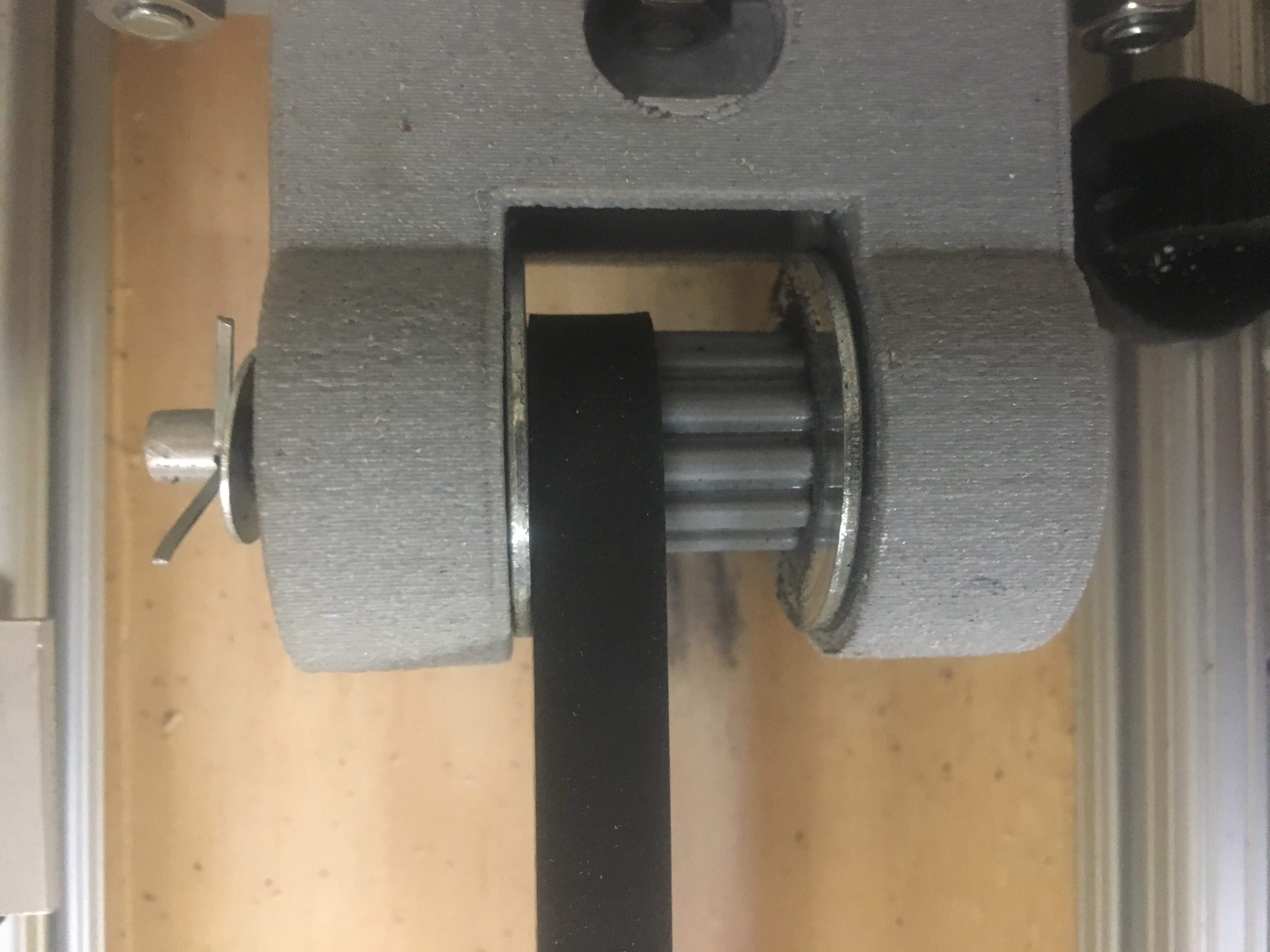
We have at present a 3-D printed gear at the idler end.

One of the idler gears we purchased was drilled well, but the gear was not machined correctly. The other idler gear was hand drilled with drill press and the hole isn’t sufficiently centered. The 3-D printed gear is doing very well at present. It has been treated with Acetone vapours and is so smooth/hardened sufficiently to not adversely affect the belt condition; atleast not so far.
Carbon Fiber Delivery head
We printed our own gears for the Carbon Fiber Delivery head. 3-D pics of these are shown below.
WP 3D Thingviewer Lite need Javascript to work.
Please activate and reload the page.
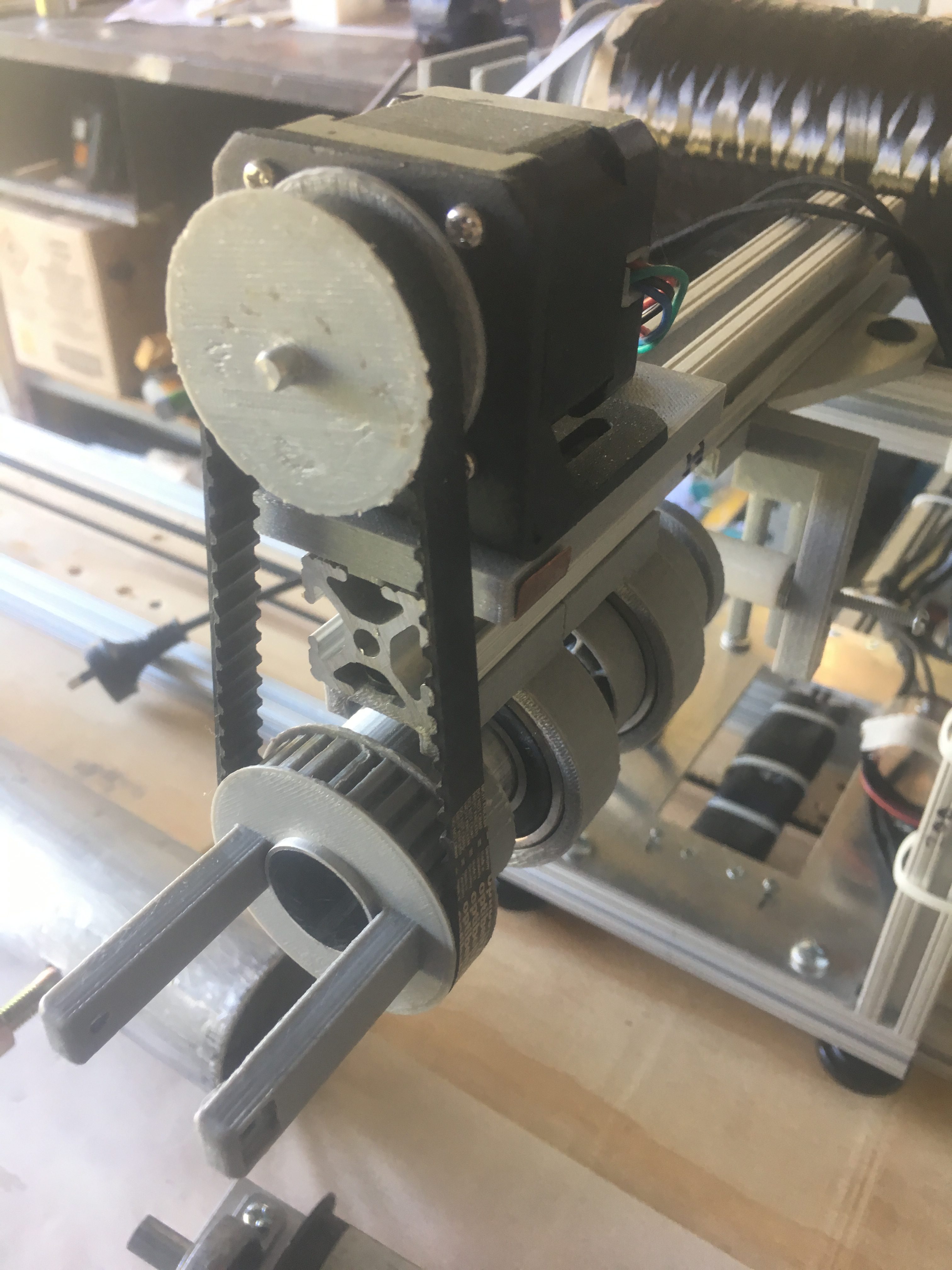
We used these 3-d printed gears because they allowed us to easily come up with design that could be fitted on to the aluminum shaft, which the carbon fiber runs through.
Here is what it looks like in real life.

Spindle Set-up
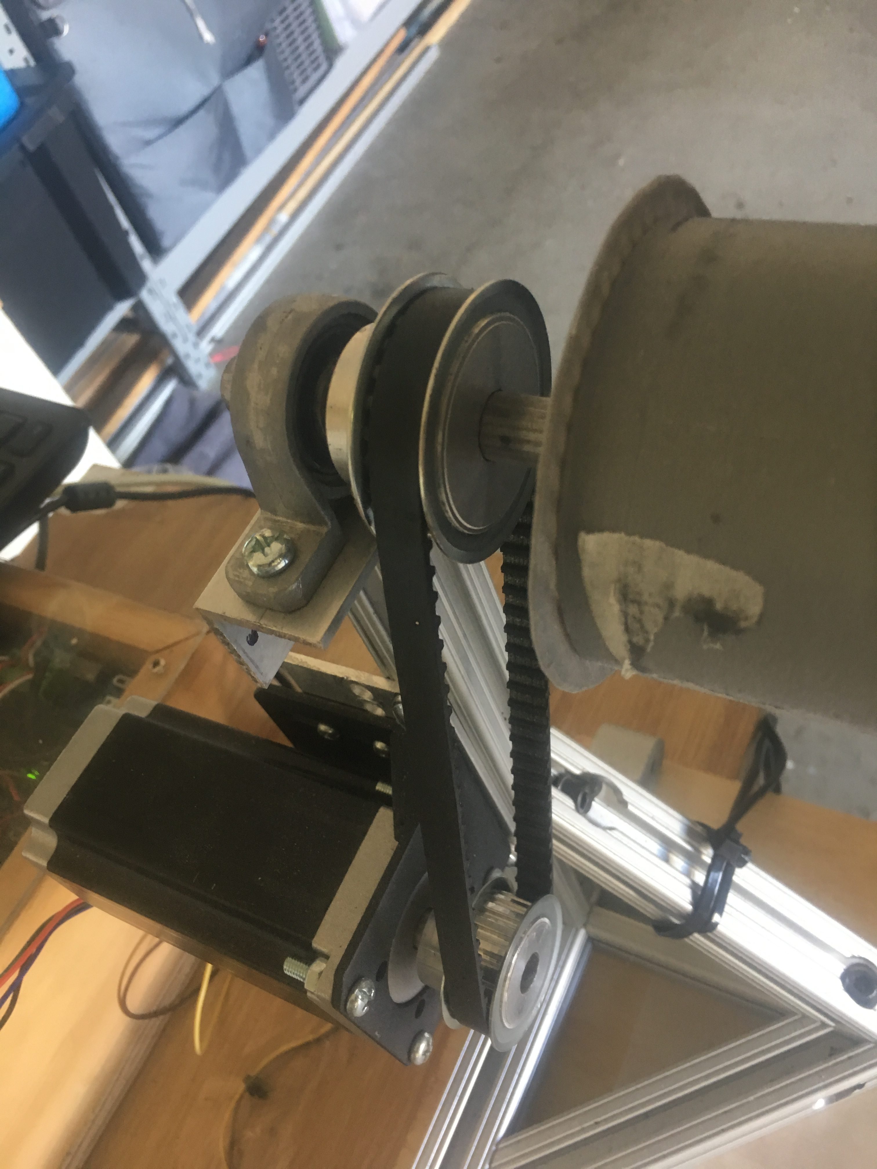
We have 20 teeth gear mounted on the shaft stepper motor and 30 teeth gear mounted on the 12mm shaft that ultimately drives the mandrel. These were drilled using a drill press and so the bores are not perfectly aligned. The alignment is not detrimental to the operation of the spindle.
Below is a screenshot of the set-up

As you will notice, the stepper motor is mounted on to the post. This was not actually by design, but out of necessity because the wrong belt was purchased. This has worked out well nevertheless, by reducing use of important realestate on the bench.
