All posts by joeadmin

Making a good batch of glue for External Fillets

It became apparent after painting my first external fillet test, that I needed to do a little bit more practice to perfect the fillet. The paint revealed the craters and irregularities. They could not be ignored.
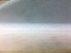
 

Original External Fillet Attempt. Notice the cratering.


Thinking about Cooking

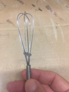
It occurred to me that if I could make better pancake mixture, I could probably make better glue. My pancake mixture always has bump/lumps. I use a whisk to beat the bumps out. So I decided to try and whisk the glue with a ‘baby’ whisk. This helped remove the lumps, but I think it also introduced air bubbles; which are something else we want to avoid.

The outcome was a surface that was considerably better than the first one, but still had some craters.
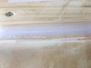
An improved fillet, but still has craters

I decided I had to try and resolve this problem without a whisk. So I decided to use a sieve to filter out all the lumpy 403 filler. I performed the filter process twice on the 403 filler.
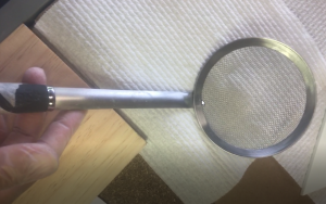
Sieve we used to remove lumps of 403


I also decided to use a bowl, rather than a cup to mix the mixture in.
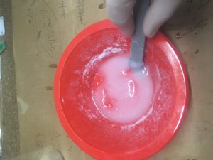
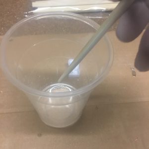
Slowly mixing the epoxy with filler.

I used a ‘paddle’ like stick, rather than the chop-stick and I was very careful to keep the stick in the Epoxy all the time, and stirred very, very carefully, so as to not introduce air bubbles. When I was adding the 403 filler, I only added it in very small amounts, covering the surface.

The result was a better mixture, that when sanded down was almost perfect!
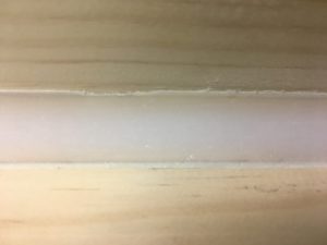
External fillet after sanding

I also used masking tape to help stop the external fillet from producing a non-straight edge. This helped.

One of the mistakes I made here was that I didn’t pull the tape off BEFORE I left it alone to dry. The result was that I couldn’t pull off all the sand paper or sand it away completely.

I used 19mm dowel with Grit 80 sandpaper wrapped around the doweling. After some sanding, I then used 240 Grit sandpaper. I think I’ll try gluing the sand paper to the doweling next time, use some
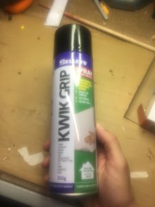
Selleys spray glue and masking tape to keep it together while drying. So many improvements being thought of!

Next Steps

I’m going to do two more trial runs before I do the rocket fillets.

External Fillets – First Trial

What I wish to create

I’ve started creating some external fillets on my test fin using West Systems Epoxy. I wanted to make 1cm fillets on both sides. So 2 * 20 = 40cm of fillets in total.

The radius of curvature is 1cm.  With some simple calculations I determined that I needed about 17cm^3 of material. I decided to make a lot more, so that I didn’t run out.

Materials

So I used:-

  • 25ml  of 105 Resin
  • 5ml of 206 Hardener
  • Approx 4 grams of 403 – to get it to peanut butter consistency, where it would not drip. This is a bit of a visual ‘job’, don’t try to measure it accurately as the scales aren’t accurate enough.

I put this mixture into a plastic bag and cut a small hole in the bag and then used this like an icing bag to squirt the epoxy material into the fillet.

The area to fillet had already been sanded with Grit-80 and cleaned. I used some clothe to ensure no dust/crud there.

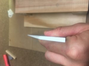
After applying the epoxy material I used my new tool a 2cm side 10cm long stick with a 2cm diameter semi-circle at one end, to form the fillet profile I wished. I then used the other end to scrape off any material left over.

Here are some pictures taken during the job.

Measuring out 25 ml of 105 resin.
Measuring out 5 ml of 206 hardener


Baby whisk used to mix the 403 into the 105/206 epoxy. This ensures that we do not get lumps.

I did not use the whisk in the first batch, which in turn was on BOTH sides of the fin. The second batch was done with the whisk and was used to fillet up two pieces of wood. The consistency of the epoxy was significantly greater, though still not perfect.

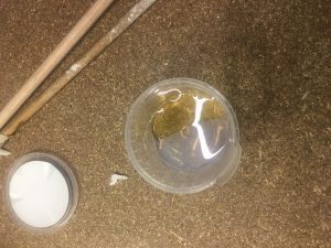
Mixing the 105/206 epoxy together for 2 minutes.


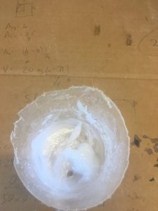
Really good batch of 105/206/403 - well mixed!
Really good batch of 105/206/403 – well mixed!
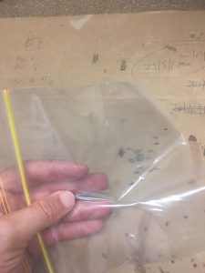
We use a snaplock bag like an icing bag. We cut a small corner off and squeeze it out.
1cm radius semi-circle "spatula" that I made to produce the external fillet
1cm radius semi-circle “spatula” that I made to produce the external fillet

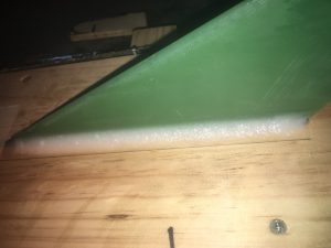
Results after curing (before sanding)

Close up view of left-hand-side fillet. Looks a little bumpy.
Close up view of right-hand-side fillet. Looks well formed, but is a little bumpy.
Comparing fillets on both sides. They look roughly the same width.

I forgot to lay down tape 1cm from fin/wood interface. I will do this next time to ensure fillets are uniform along the length.

I tried using methylated spirits on my finger to smooth the paste, but this failed.

I will use a sieve next time to introduce the 403 into the epoxy mix, as I believe I’ve introduced air that is causing some issues with the quality of the fillet.

Sanding

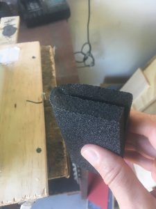
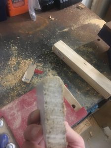
I’ve started sanding with flexible sanding pads. I can bend them back on themselves to produce a pretty good sanding block with a semi-circle end. I have used coarse, then medium and finally the fine version. I used some water as well to get a finer finish.

Flexible sanding pad. Notice the Semi-circle end that is produced. Makes for a good way to sand the fillets


Practicing preparing and attaching a fin to “Motor Mount”

I’ve purchased some real G10 material to practice on. What I wanted to practice was:-

  1. Learning how to cut it well (even though this isn’t required for this build)
  2. How to sand the Leading and Trailing edges to the profiles I’ve decided.
  3. Sand the root and tang to Grit 80. Also sand other edges lightly with Grit 80 to remove any burs. (But I don’t want to change the shape)
  4. Sanding back with Grit 240 to give it a good finish for painting. I sand it ALL over, except on the tang, and the root where it is glued on the motor mount
  5.  Score the root of the fin (yes, on the thin edge) using a punch and a bit of elbow grease. Did this every cm, in both directions at 45 degrees
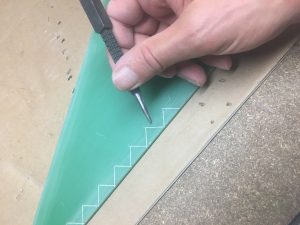
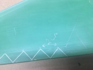
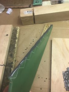
  6. Score Tang of Fin that is going to be below the air-frame. I did this every 2cm at 45 degrees in both directions
  7. Cleaning the surfaces thoroughly with Methylated Spirits
  8. Inspect the fins to make sure there is no other dust, grime or dirt.
  9. Perform the following preparation steps
  10. Attaching to “motor-mount”
  11. Test paints – to see how finish is.


Preparations Steps

Before I can begin attaching fin, I need to prepare my work area. The “main” steps are:-

  • Clean desk
  • Get Methylated Spirits
  • Get Paper towel
  • Get a clean wood board for mixing Glue and mixing stick
  • Get my Timer
  • Wood blocks
  • Get G-Clamps.

Steps to attach the Fin

We can’t do these steps until the fins are prepared!

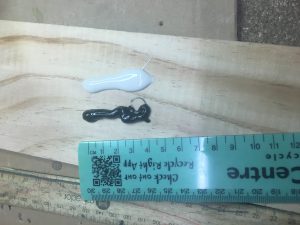
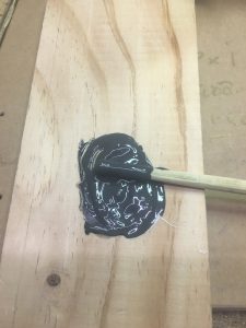
  1. Then I mix up equal amounts of J-B Weld black and white on a clean surface for mixing.
  2. I start time for 20 minutes. This tells me how long I have to go.
  3. I apply this to the root of the fin as evenly as possible, and try and avoid it going over the side
  4. Clean off excess J-B Weld off sides very carefully using Methylated Spirits and paper towel.
  5. Carefully lower the Fin into the slot, make sure that the J-B Weld doesn’t get on to the “Air-Frame”
  6. Apply a bit of a wriggling action to get the glue to fill gapes
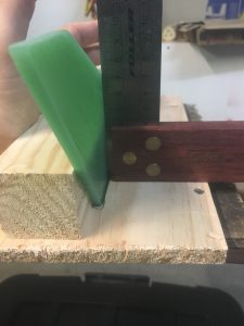
  7. Make sure the Fin is 90 degrees and use clamps and wood blocks to ensure that the fin cannot move
  8. Leave it for 15 hrs minimum!

Here are some pictures:-

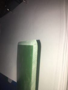
Rounded leading edge.
V-profile trial sanding.
Using a punch to score the tang
Scoring on the Tang
Scoring on the Tang
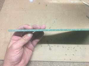
Scored the bottom of the fin.
Approximately 4cm of glue should be enough for 20cm of root fin with some glue left over.
Mixing the J-B Weld glue for a minute.
Glue carefully applied to root.


Using square to get fin at 90 degrees to wood.
Fin installed in the slot.


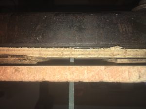
Trying to show fin/glue inside gap.


The Glue Gun

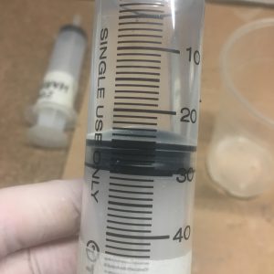
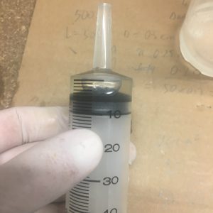
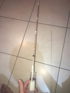
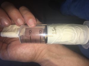
I need to create internal fillets against the fins between the motor Mount and the Air-frame. The gap is very small – ~12 mm. So I’ve purchased some 5 mm diameter tubing with some 50 mm syringes to get the glue down there. I have used some thin doweling with masking tape to help direct the end of the tube to where the glue needs to go. Below are a few pictures:-

We have marks every 2 cm. Each cm corresponds to approximately 1 cubic cm of araldite.


We will only need about 21 cubic cm of Aradite per fillet.
Yes, the glue gun will easily fit up the gap between the motor mount and the air-frame.

The process will be:-

  1. Suck up 25 cubic cm of Araldite into the gun
  2. Clean end
  3. Insert gun up to the ‘zero’ mark
  4. Push 1 cubic cm of araldite in
  5. Withdraw 1 notch

Repeat step  4,5 will tall the way out

Purchase of the Glues

I’ve finally purchased glues for the rocket.

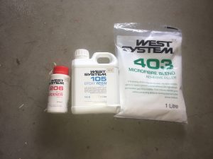
I have West Systems 105, 206 and 403 filler for the external fillets.

IMG_3122

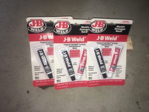
I have J-B Weld Epoxy for the root fillets.
IMG_3124

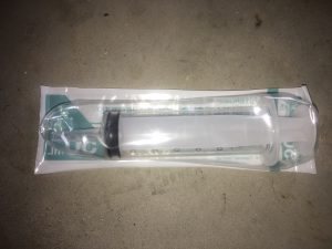
For the internal fillets, I’ll probably be using West Systems 105/205 (no filler). What I will need to get the epoxy up the rocket into the area of interest is a tube/syringe.


IMG_3123

Yet to purchase the pipe.

Fin Slots in Airframe

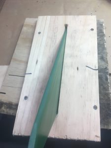
I’ve discovered that the fins are not exactly (or even close) to 120 degrees apart. The distance between two sets of fins is the same, while the other Fin/fin distance is greater than the other two by 5mm. Not terribly good. What this means is that the Jig that I made to hold the Fins in place ONLY has perfect alignment in ONE position. i.e. I cannot rotate the rocket and have the fins line up in the slots of the wood.

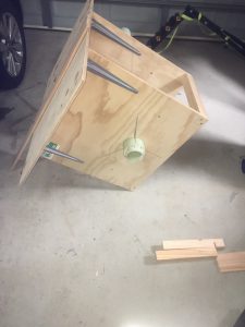
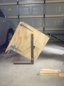
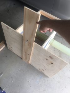
This has meant that I need to change my fin install procedure, by allowing me to rotate the WHOLE Jig into position, so that each fin that is being glued is vertical. I’ve done it as follows

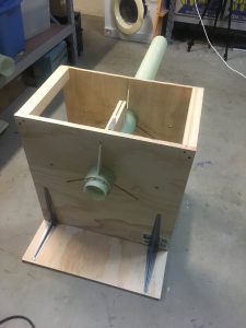
Wooden stand
Wooden stand


Stand in action. Left hand side is raised 30 degrees
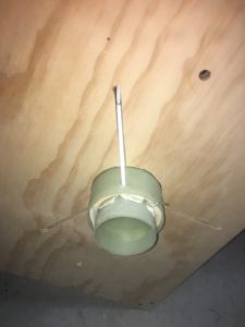
Fin inserted into slot


Checking slot with a Square to make sure it is close to vertical


We can take the wood stand off and attach it to the Jig, pointing out the other side. This allows us to install the other fin pointing down to the wooden base.

Fin Work Preparations

The next step is to profile the fins and to score/sand the roots and tangs. Some important decisions to make are:-

  • How to evenly sand the surface of the fins (so it is symmetrical)
  • What profile is required – at leading edge and trailing edge.
  • How to score the fins

We concentrate on the first two here.

Fin Symmetry

When I examined the fins, the first thing I noted was that the chamfer in them is not symmetrical to begin with. This is unfortunate, but I’m just going to have to work with it.

Shaded view shows size of chamfer. Notice different width.


Notice the lack of symmetry.

Well, that is something we will need to work with. I had a vision of a semi-circle shaped leading edge, but this is probably not possible now. Will probably make them parabolic, or elliptical in shape.


The tools to sand down the fins

The first tool I created to sand down fins was the following:-


The problem with this is that the sandpaper lifts off from the surface and interferes with the sanding process. The area of sandpaper available sanding is reduced because it needs to be sandwiched between the pieces of wood. Because the longest section of fin to be sanded is 250mm, this means we can’t sand the edge down (along the whole length) in the same stroke. This is a big disadvantage, and was one of the identified issues we wanted to solve.

Some tests were done to see if we could get a nice job done using wood and it looks like it “should” work. See below:-

IMG_2925


Good finish on wood - both edges.
Good finish on wood – both edges.

As you can see, the edges look very well curved. I did this curve by doing sanding at ~30 degrees, ~45 degrees, ~60 degrees. Then I did a ‘curving’ action to try and get it rounded. This makes a ‘semi-circle’ like edge.

I decided to build a simpler sanding plate. I needed:-

  • Sandpaper
  • Spray Glue
  • Plywood
  • Clamps
Spray Glue
Spray Glue
Sand paper and Plywood

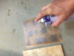
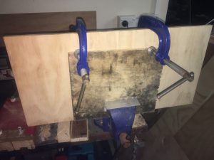
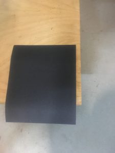
I followed the instructions very carefully. Spraying both the sandpaper and plywood, then letting them sit for 10 minutes. Then I put the two together and I clamped them over night. I decided to put 80-grit sand-paper on one side and 240-grit sand paper on the other side.

Applying Spray glue to sandpaper and to the plywood.
Letting sandpaper and plywood sit for 10 minutes.
Clamping sandpaper and plywood for overnight dry session.

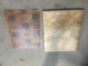
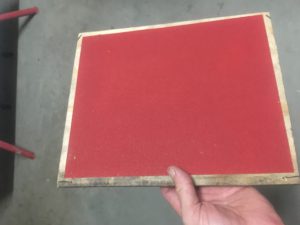
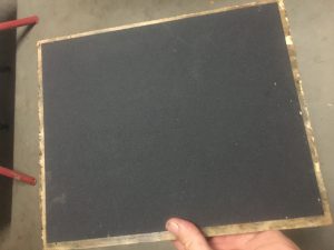
Here is the end result.

80-grit Sandpaper on one side.
240-grit Sandpaper on one side.

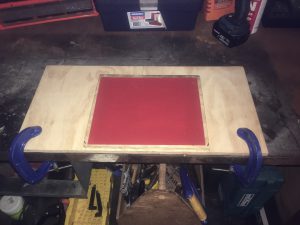
Notice how there is some bare plywood accessible on the edge of the sanding board. We have drilled some holes into this can can mount this to a large piece of plywood. This allows mounting the sanding board on a solid (non-moving) bench. See below.

Fix sanding board to big piece of plywood which in turn is clamped to desk


Assembly Jig for Attaching the Fins

One of the steps I’m coming up to is the attachment of the fins to the Air-frame/Motor Mount. For a good join and a good rocket build it is important that we:-

  • Sand/score the root of the fins
  • Sand the Motor Mount where they are going to be glued
  • Sand/score the Tang of the Fins for the fillets later on
  • Important that the Fin/rocket do not move for 3 days while it dries
  • Very important that the fins are precisely 120 degrees apart and are perpendicular to the air-frame

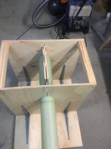
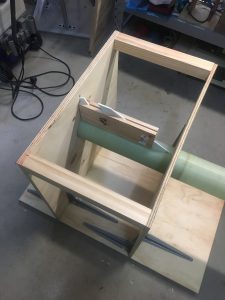
The the last two bullet points, we have build up a “jig” to hold everything in place. Below are some pictures of it.

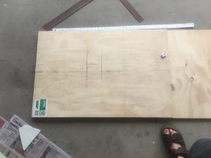
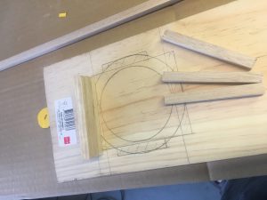
Marking where to cut out circle


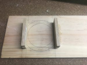
Two pieces of wood assembled so we can cut out circle sections together.
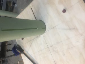
Cut out circle and marking where cut-outs are going to be for protruding fins.


Fin Assembly from back. Notice the right-angle bracket to keep it vertical.
Fin Assembly from front


Side view showing how fins are kept in line with two pieces of wood and three bolts.
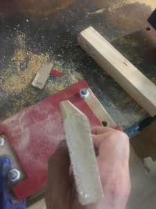
 

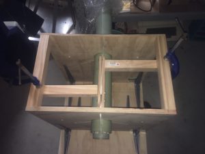
We want to hold the fins completely still while it is drying. For this, we have used two square pieces of timber and some G-clamps to keep the fins steady. See the photo below.
Fins held in position using wood braces/G-clamps.


Gluing Motor Mount inside Airframe

I have checked the steps many times over several days, trying to make very sure I have not mis-understood anything, measured anything incorrectly, missed any steps that might be good to do now.

I then performed several dummy (pretend) attempts at gluing the motor mount into the Airframe, to help me anticipate any potential issues and also have the best procedure to glue this motor mount into the Airframe. I was able to confirm that I could see where the glue was in relation to the lines inside the air-frame.


Making a batch of 24hr araldite glue


I made two batches of araldite actually. Wanted to make sure I had more than enough glue.

I put glue on the stick end and turned in my hand as I put it down in between the two lines. I used the cut-out in air-frame (for the fins) to ensure I got the glue in the right spot. The occasional motion of the air-frame stopped glue from dripping from the edge and allowed me to paste a nice layer of araldite in the air-frame. Then I loaded the motor mount  and twisted in back and forward to ensure the glue was spread about in between the centering ring and the air-frame.

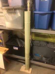
Then I put the whole rocket into the vertical position as shown below:-

Air-frame is cable-tied to the shelving in our garage.

The glue requires 24 to 72 hours to completely cure. So we will give it the complete 72 hours (Sunday 09:30 to Wednesday 09:30). We want the BEST possible result


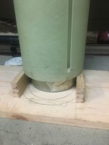
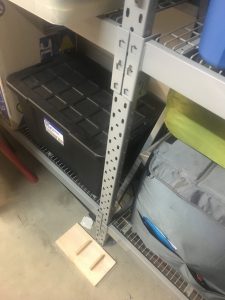
We checked that the motor mount was indeed sitting 27mm outside the end of the Air-frame. See the photo below.

Motor mount is resting on wood bottom.

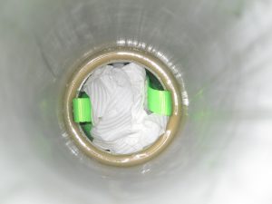
I had a look from the top to see how it looked.

Top view of 24hr Araldite


Preparations for gluing Motor Mount inside Airframe

A lot of work needs to be performed before we can attach (glue) the motor mount inside the Airframe. Below is a list of steps I have done:-

  1. Mark out where the Motor Mount needs to be glued in relation the end of the airframe
  2. Mark the upper/lower points inside the air-frame where we need to apply the Araldite.
  3. Choose the Glue to use for the joint. Will go for 24hr araldite because it is easier to handle (more viscid), doesn’t set as fast, so giving more time to apply and have a stronger bond.
  4. Cut off a piece of doweling and mark on the stick where it  is right up to the crucial part of the air-frame requiring glue. I rounded the ‘glue’ end to help in application of glue.
  5. Creating of a stand which will sit the rocket on to ensure that the Motor Mount protrudes from the Air-frame the exact distance – 27mm
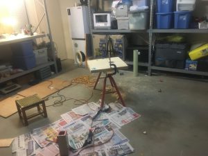
  6. Find and set-up a place where we can erect the rocket to dry for 24hrs.
  7. Scuff the Motor mount where the Fins are eventually going to be attached.  Made sure surface is clear or dust and rubbish. Easier to do this BEFORE the Motor Mount is glued in.
  8. Make sure no tape left on motor mount
  9. Inspect the Top centering ring to be very sure it is glued sufficiently well.
  10. Tape down Nichrome wire to the bottom of the motor-mount so that it doesn’t get in the way

As you can see there is a massive amount of preparation before we even start applying any l glue.

Below are some pictures of the pieces worked on in this preparation.


IMG_2716

Construct the wood rest. It consists of single piece of wood with two 'walls'. Each wall is made of three pieces of wood (9x9) superglued. The airframe rest on the wall, the Motor-Mount drops 27mm down on to the wooden base.
Construct the wood rest. It consists of single piece of wood with two ‘walls’. Each wall is made of three pieces of wood (9×9) superglued. The airframe rest on the wall, the Motor-Mount drops 27mm down on to the wooden base.


IMG_2719


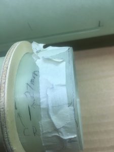
Image of Centering ring on motor Mount. 27mm mark on Motor mount must be inline with Airframe bottom.


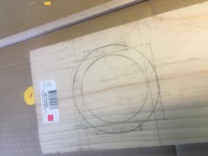
Ground wood system where rocket will sit (vertically) while drying.


Image of air-frame with marking inside the air-frame visible. These marks indicate bounds of where I want to apply the Araldite