
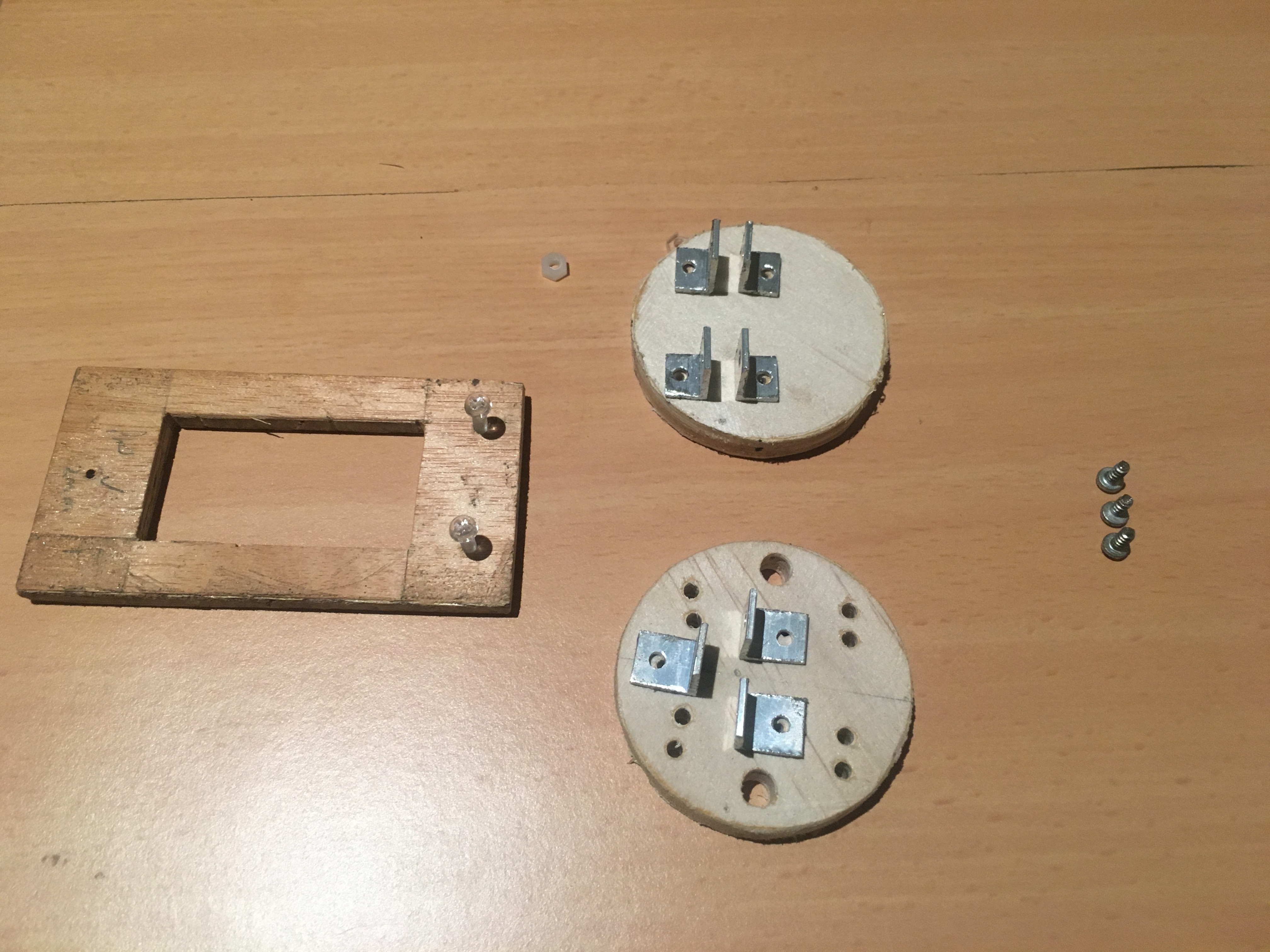
We are creating a payload bay that will house the electronics and ultimately all the rest of the hardware. For now, we only require it to take the electronics, which will be all that is needed for the first few flights, to obtain sample data from the Gyroscope. We are leaving enough space so that we can later install stabilisation motors.
This of course is a smaller, cutdown version of the ultimate rocket we wish to launch. However, we want to get a smaller version of this rocket Stabilisation system working on a small one. A proof of concept.
Here are components that make up the electronics bay (just one part of the payload).
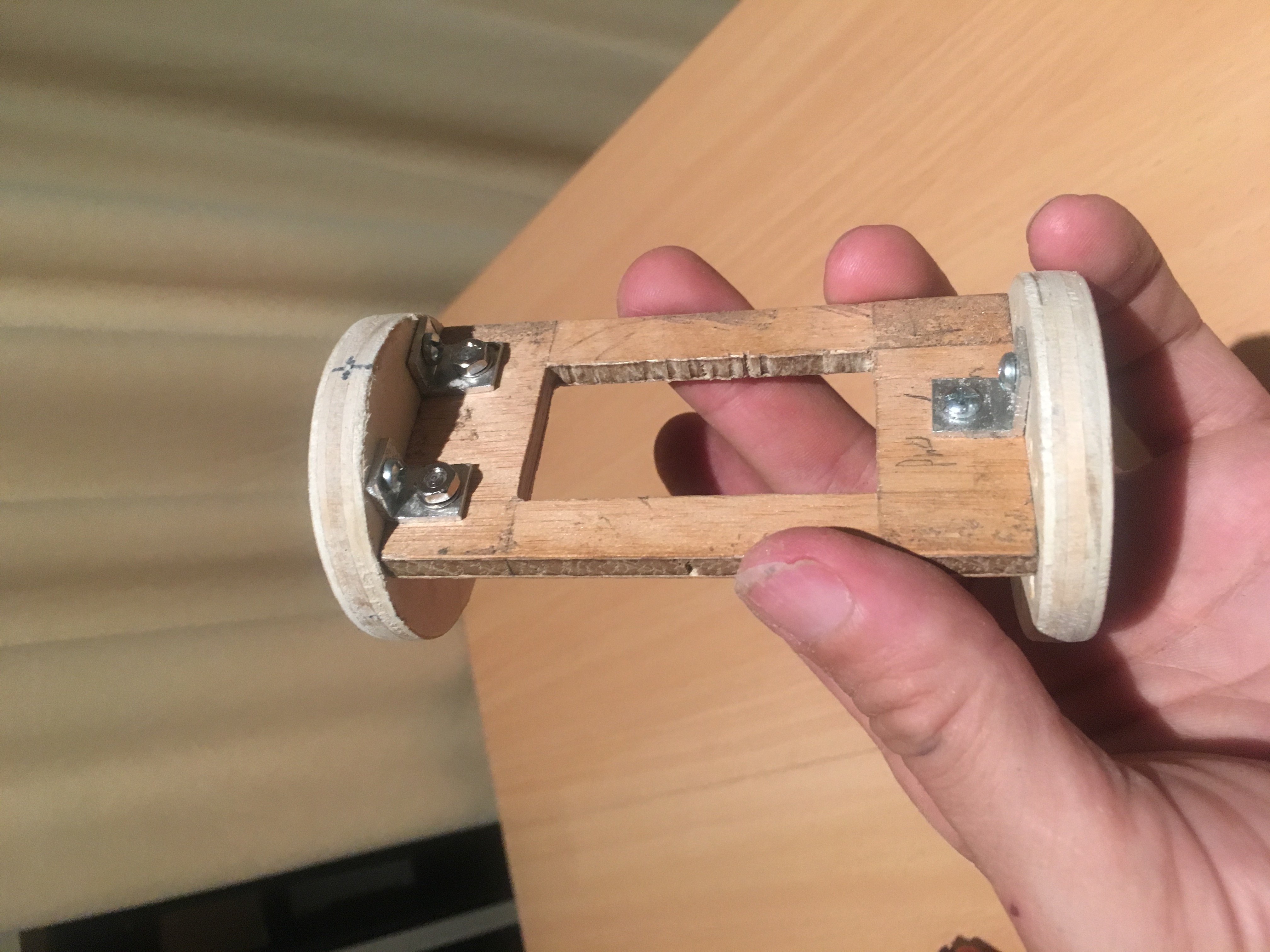
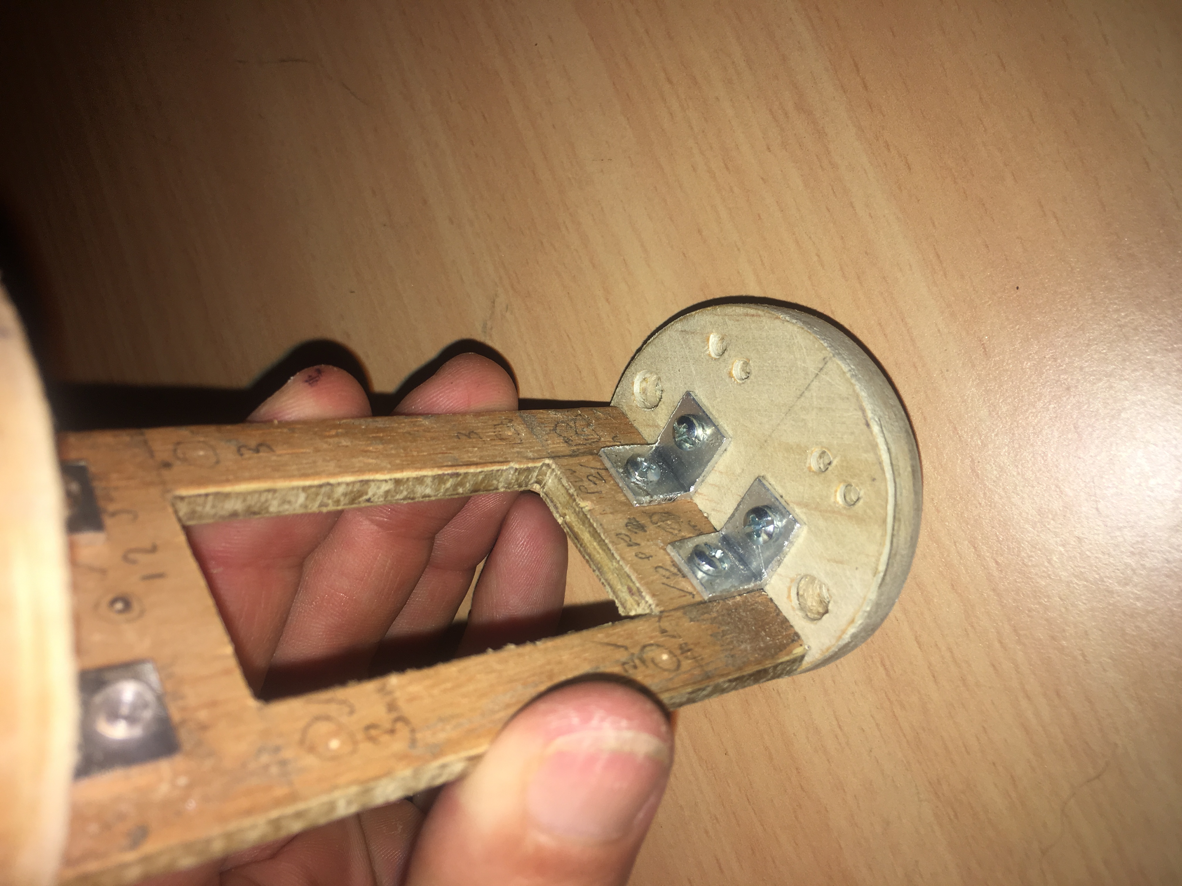
Below are some pictures of the payload bay, partially constructed.
A rotatary switch will be installed between the top two brackets. Holes will be drilled on either side of the tray, to which we will attach the PCB. Some of the PCB breakout boards will actually sit within the cut-out in the tray. i.e. this cut out is more then just a weight saving measure.
We hope to get the electronics components later in the week and start building and attaching to the payload tray. We will provide a new Post when this is complete.