
In this post we focus our discussion on the device used to adjust the Centre of Mass. This device consists of two masses that we rotate independently to produce a resultant change in Centre of Mass. We split the masses in two to:-
- Halve torques required to rotate them (if they were combined)
- Allow us to obtain neutral position (by having masses opposite each other)
- Allow movement of Centre of Mass around…by moving masses
- Reduce movement of Centre of Mass by moving masses apart
This isn’t a new idea. We solved this problem with stepper motors. Unfortunately the stepper motors have problems. The are:-
- Too heavy
- Have insufficient torque
- No means of verifying the position
- Large current requirements
- Require specialized electronics – Driver board
So I put some thought into how we could make this lighter and have greater torque. The only solution I have been able to come up with is a geared system using high torque servos.
The trade-off is that we can’t continuously rotate around. But this shouldn’t be necessary because we only need this system to operate for the first 1 to 2 seconds of flight. We do not expect the rocket to rotate about it’s Y-Axis significantly. Put another way, we don’t expect erratic motion, instead some clear rotation in one plane that requires some correction. There may be some rotation as the rocket builds up speed and the fins (with their imprecise alignment) results in some rotation about y-axis.
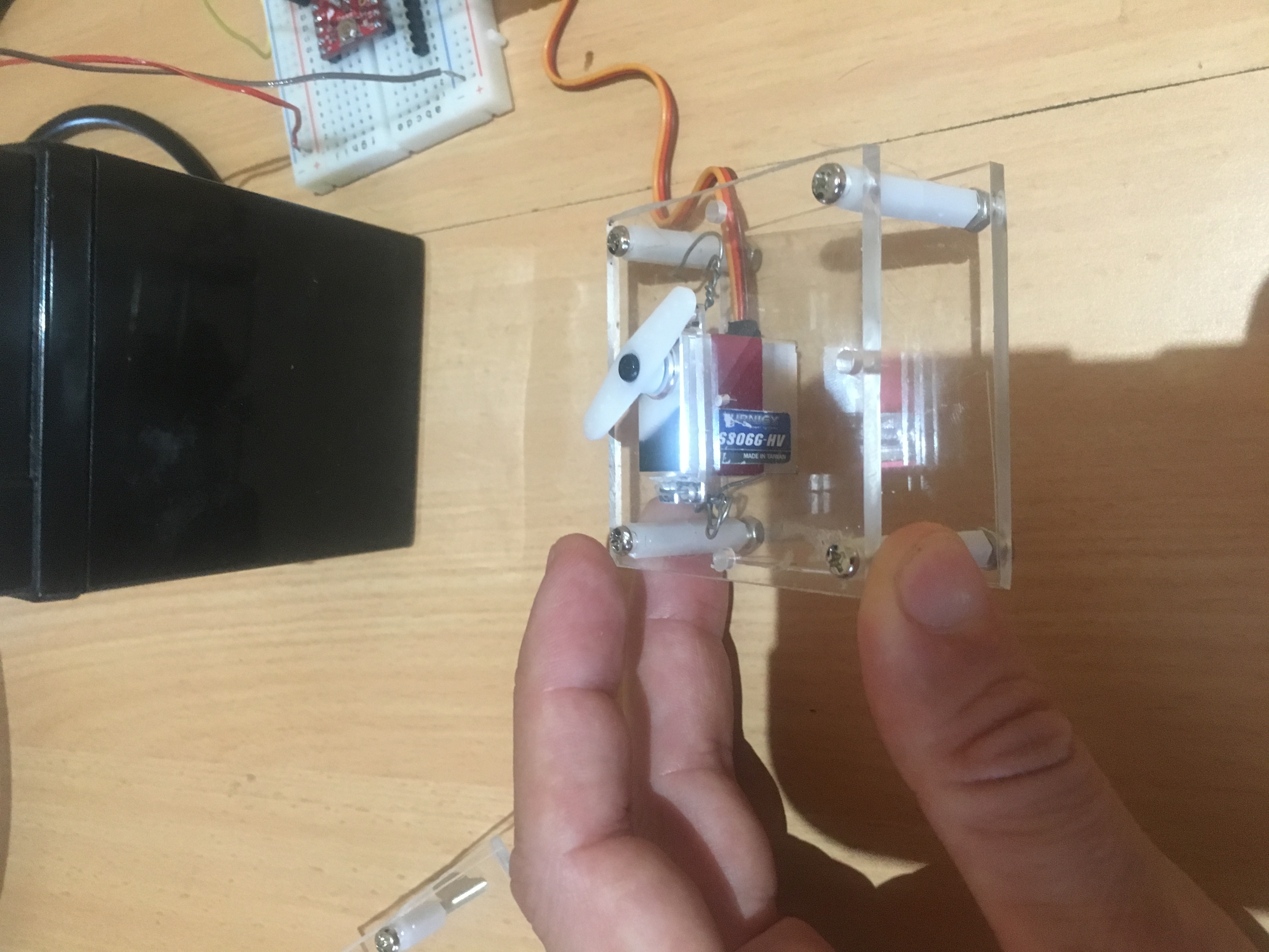
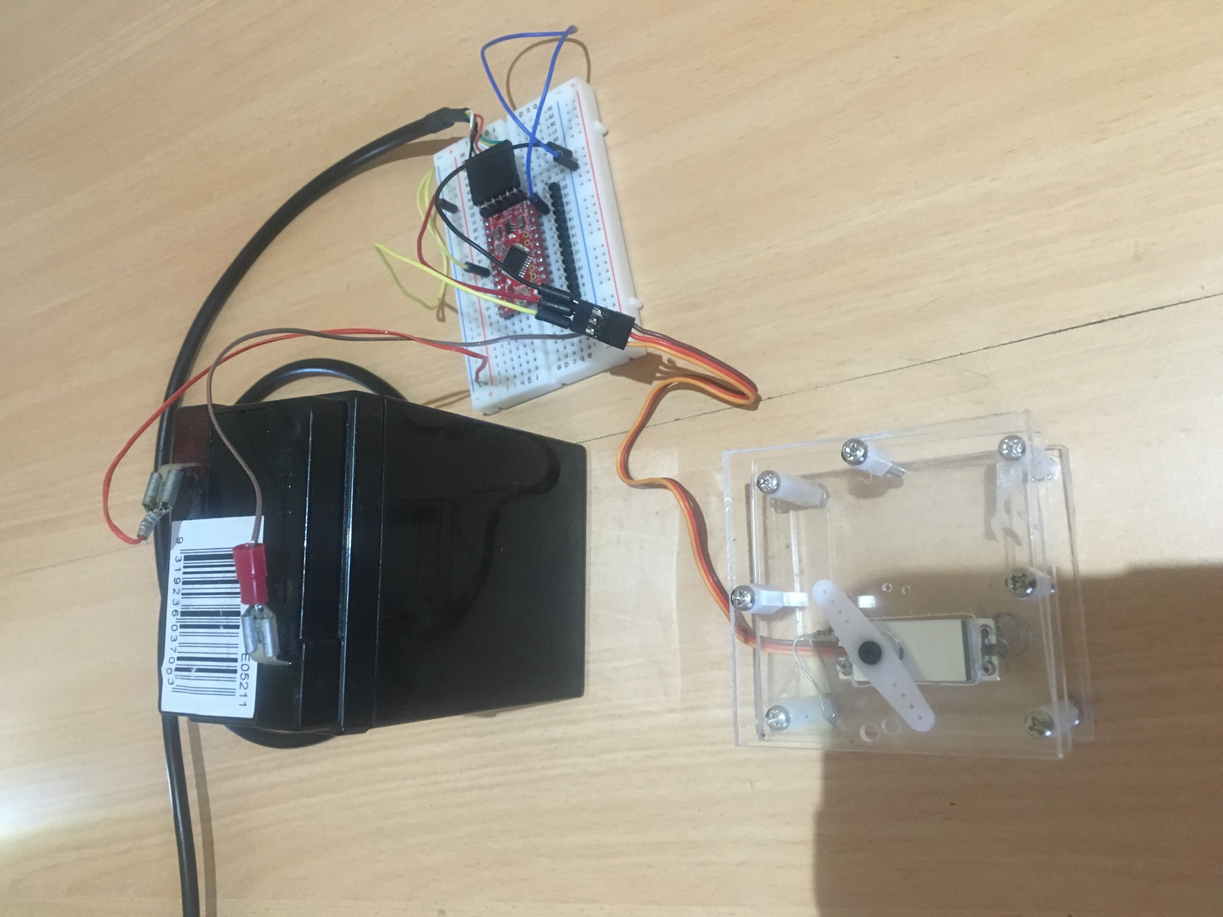
We have started work on a “pre” prototype system using Perspex. Below are a few pictures of system connected to Arduino.
We ultimately aim to have 3-D printed components to form the framework. Below is a preliminary design for the bottom section that the servo is joined to.
[stl file=”framework_v0.02.stl” ]
We have ordered components from ServoCity. This looks like a very good supplier of quality components; certainly comprehensive. Below is a picture of the parts we have recently purchased.
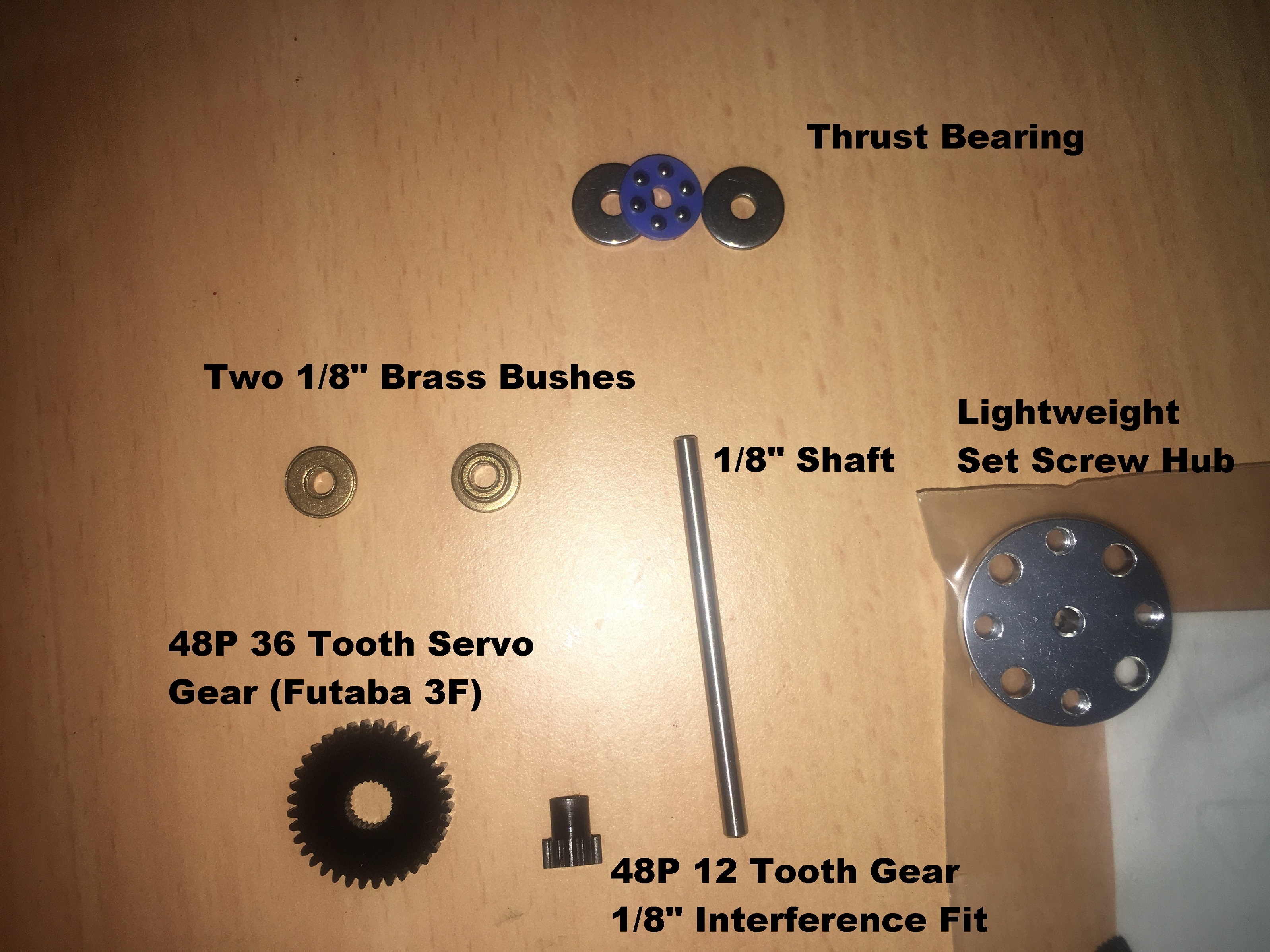
We had problems with the 48P 36 tooth gear. It was larger then the Spline on our Servo. So, I drilled out the servo gear carefully and then press-fit a Servo attachment into the gear (which I’ll later glue). Then I carefully drilled holes in the Perspex and press-fit the bushes. The final mechanism looks like:-
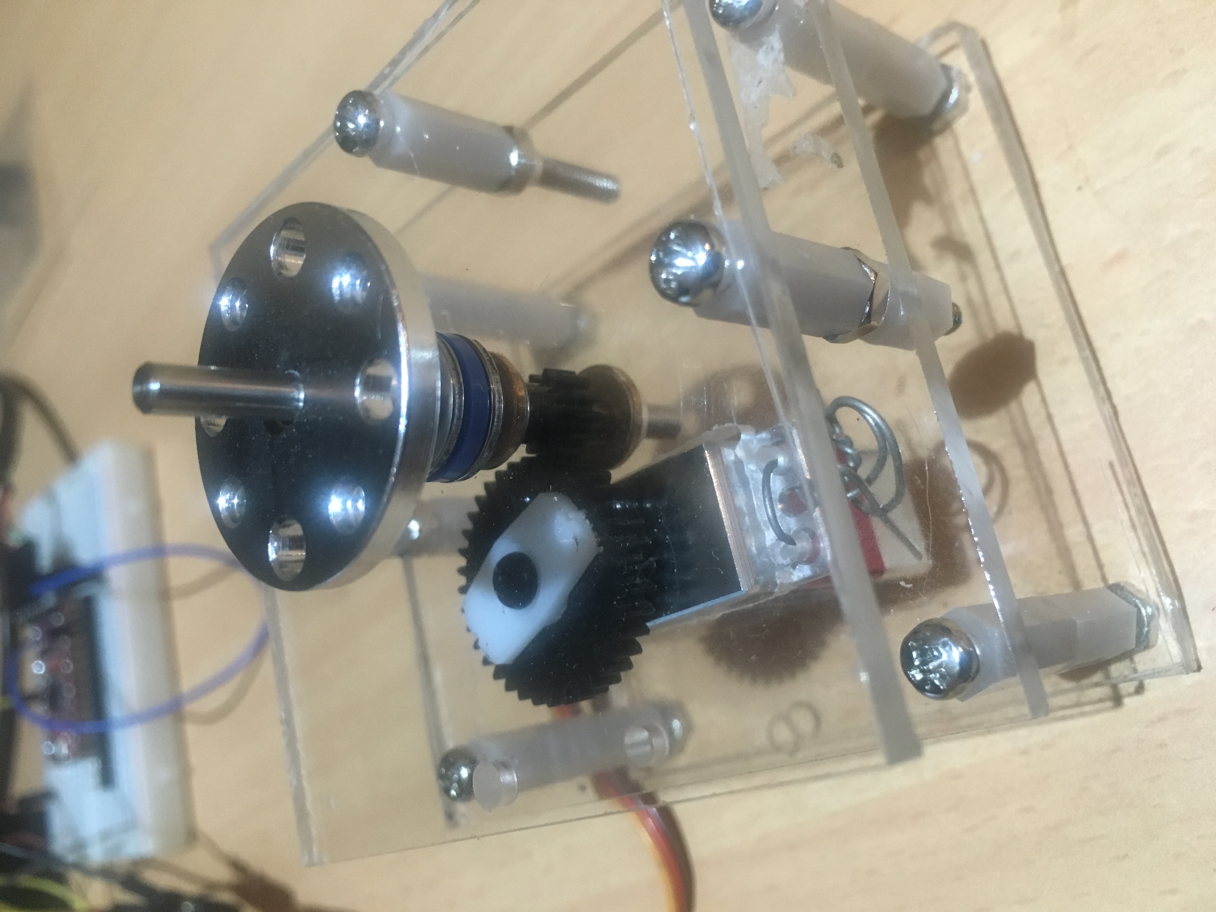
The gear ratio is 3:1.
This means:-
- Travel distance is now 3 x 135 = 405 degrees
- Travel speed is now 60 degrees in approximately 0.017 seconds
- Torque is reduced from 3.7kgf.cm to 1.23kgF.cm
We will ultimately look at adjusting the gearing,by inclusion of another 12 tooth and 24 tooth gear to give us a gear ratio of 6:1. Initial design work suggests that this should be doable. But for the purposes of the next flight test, we do not need to work on such a system. This system should be adequate for characterizing the effect of small movements of the Centre of Mass.