Installing the Buttons
Next I wanted to attach the Rail Buttons. Rail Buttons are what we use to guide the rocket up the rail. A few decisions had to be made:-
- What type of button to use – 1010 or 1515
- Where the buttons should be installed
- How to affix the buttons – to ensure sturdy install
Deciding What Type of button to use
I’ve heard that using 1010 on the rocket I’ve built has worked well for the creator/designer of the rocket. So why would I not want to go for a 1010?
Firstly, I know that this rocket can get quite heavy with certain motors, and the heavier the rocket, the more I want to be sure that the Buttons are appropriately sized – for the weight. But I wanted to err on side of caution. I’m responsible for the rocket and I have to feel comfortable with the build.
Secondly, I know that the QRS club 1010 launch rail is 1.7 metres and the 1515 launch rail is 3.5 metres. When I do simulations using OpenRocket, I get some rail exit velocities that are below 15ms-1. (15ms-1 is approximately 50feet/second). 50 feet/second is considered to be a good around min safety speed. Yes some people have managed to get away with lower speed rockets, but I want to err on side of caution.
Below is a simulation of some motors using a 1.7 meter launch rail.
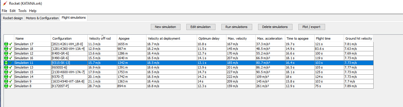
A second restriction I have at the QRS Cedar launch site is that the Ceiling height is 5000 feet. This translates to 1524 metres. With a 10% safety margin, this comes down to about 1372 metres. This means the only real contenders ar:-
- K1720ST-P
- K515-SK-13
- 1633-K940-WT-18A
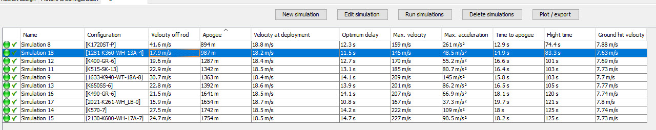
By having a 3.5metre rail, all Velocity off Rod are acceptable.
The downside of having larger buttons is increased drag – and slightly less sleek looking rocket. Also, if I take the rocket to a launch site without a 1515 rail, I’m going to have problems!
Where the buttons should be
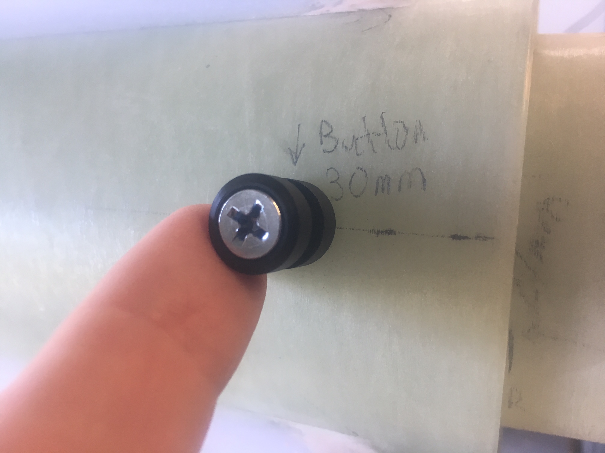
I decided to accept the button placement suggested in the Katana 4 Build instructions, which is 3cm and 45cm from the rear of the airframe. Having the button at the rear means less chance of taking paint off the rocket while loading on to the rail. The 45cm is not the most ideal position (not around CG), but it has to be here because we don’t want the button screw snagging the Drogue parachute. (At 45cm, it is within Motor Mount/Airframe cavity.
How to affix the buttons
Decided to screw into 4.5mm holes that were very carefully drilled. I added Selleys non-drip superglue (CA glue) into the hole to give the whole arrangement a little more strength. Don’t just want them popping out. I was careful here to ensure that no CA glue was on the exterior which might glue the button to the air-frame. I read that it was important to allow the button to rotate freely.
I was a little concerned that the glue might dry very quickly before I had completely screwed the screw in. So I did a test run. No issues occurred during the test run.
I wanted to make sure the buttons were mid-way between two fins.
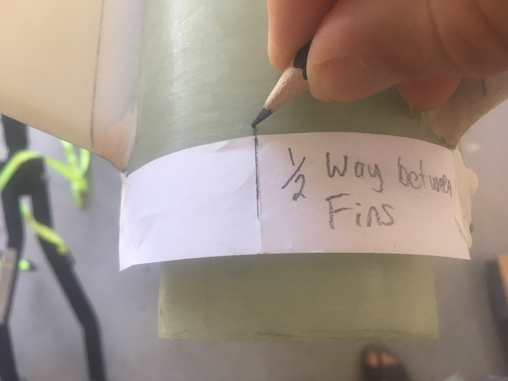
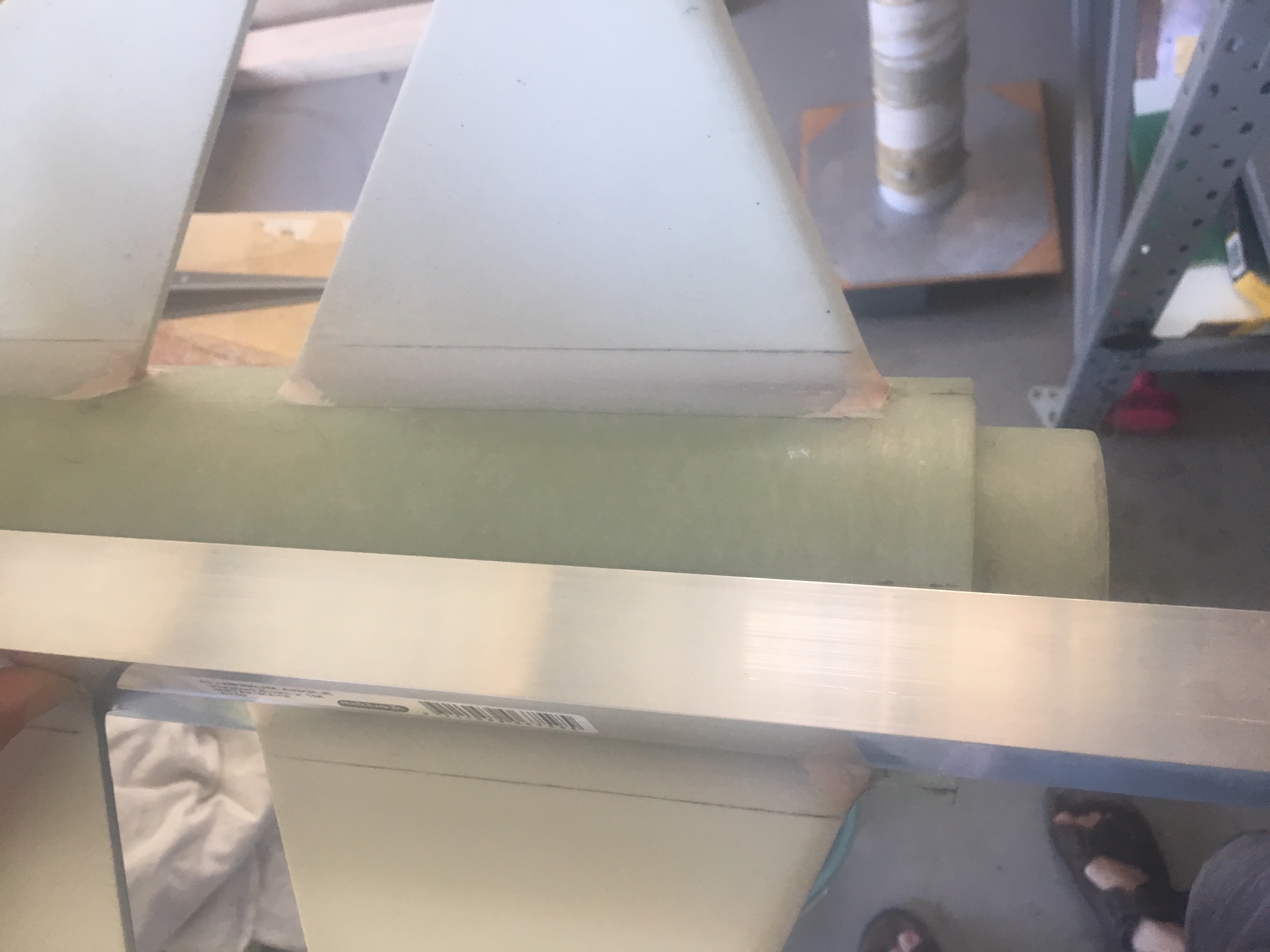
The first part of install was to mark the places to drill. I used Right Angle aluminium length and pencil.
I drilled holes very carefully making sure the drill bit was perfectly vertical. I drilled the initial hole at 2mm. Then used 3, 4 and finally 4.5mm drill bits.
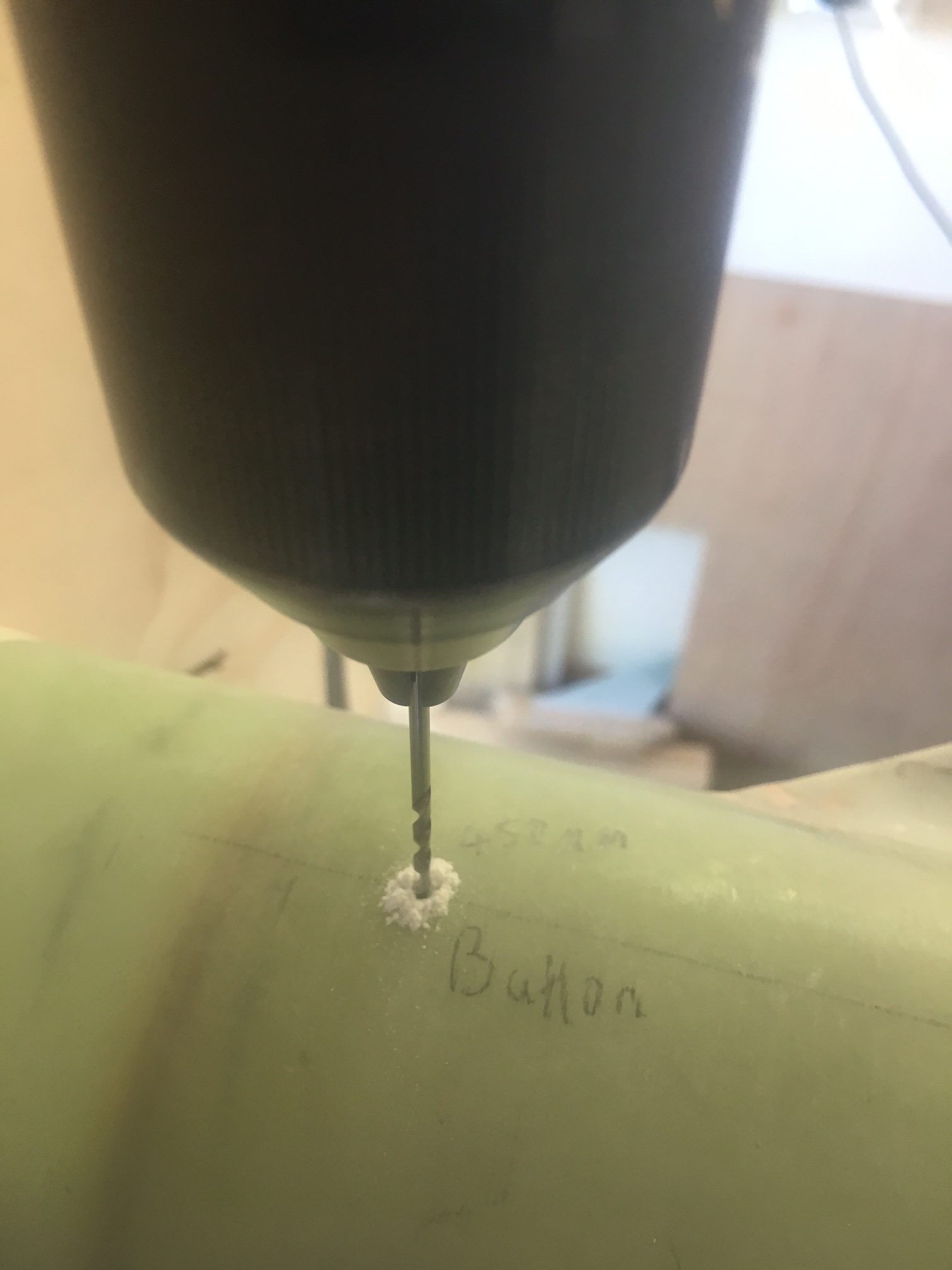
As you see, I carefully labelled every area I was to drill, double checking measurements before drilling.
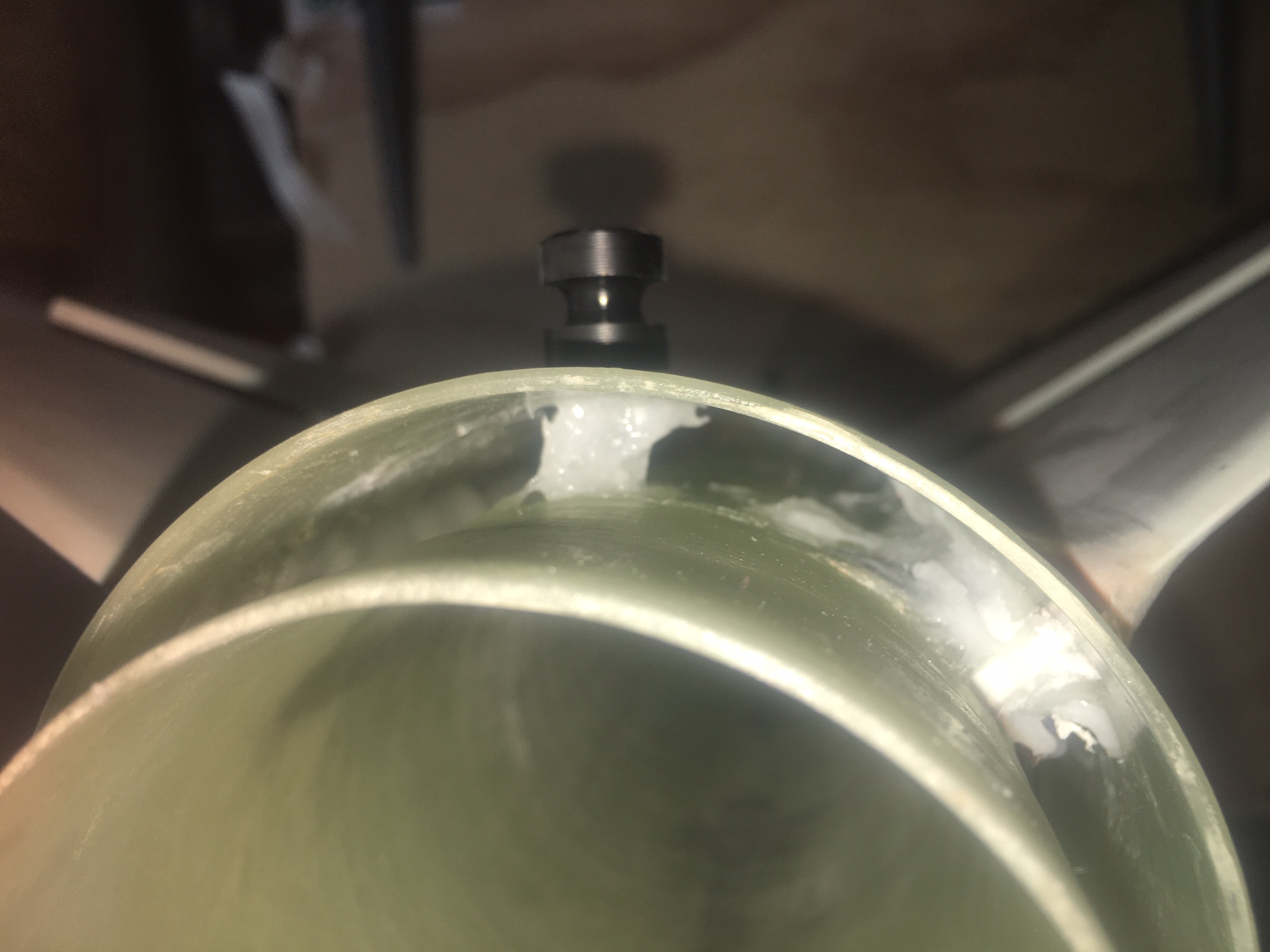
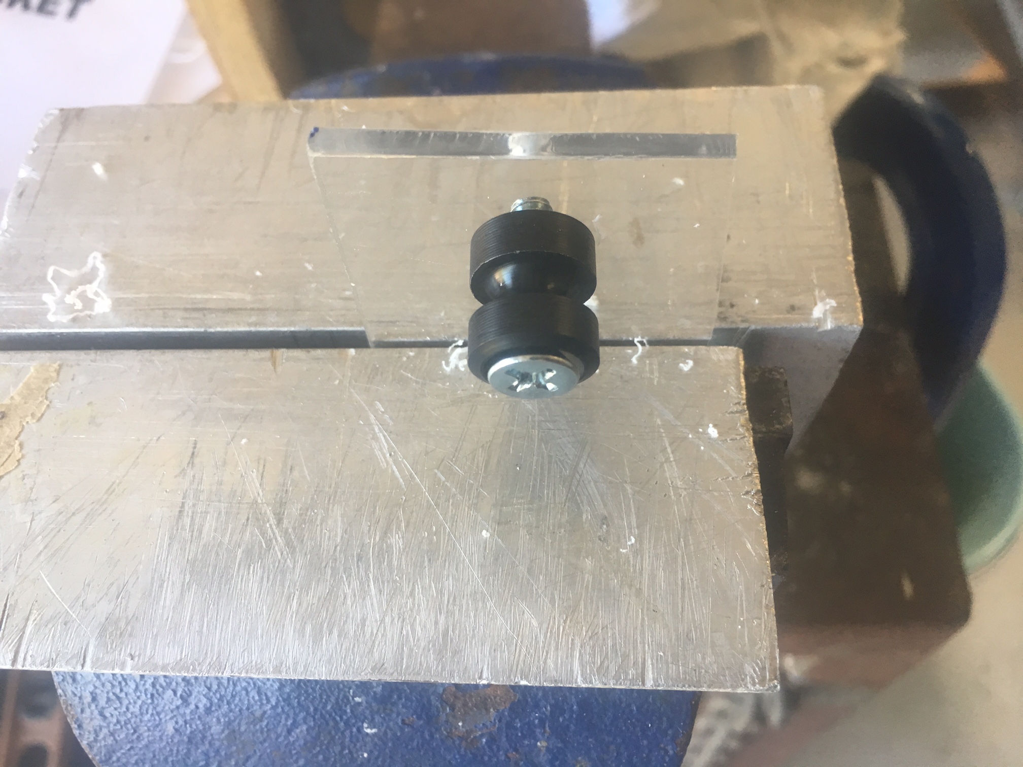
Here is how it looked at the end.
I was careful to make sure the buttons could spin,
After the buttons were installed, I put a dab of 105/206/403 epoxy on the inside on the screw. Here is how the rear screw looked. Not pretty, but it helps to take some of the load.