All posts by joeadmin

Avionics – QA – Improvements

The success of the flight is reliant upon the ejection charges separate the components and this this all depends upon the integrity of the Avionics installation.

For this reason, we review the Avionics bay to ensure that risks are identified and addressed.  Some of these counter measures are shown in previous posts and no mention was made of how we arrived at the design here.  We do this here.

Risks with Counter Measures

Switch Terminals

We were going to solder tips of wire and screw them into the terminals of the lever switch. When screwing them in, it tends to twist the entire wire around. This is probably “fine” but I can imagine that there is stress on the wire. The washer/screw should remain in place, but it is far from ideal.

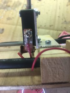
So, what I did was get some very thin copper plate and cut out a small strip, 5mm x 10mm. Then I drilled a 3mm hole at one end. I sanded down the copper pieces of both sides and on curled one end (not the end with the hole) a little. Then I soldered a wire to the copper, leaving a small gap at the end with the hole (so I don’t add excessive thickness). At the other end, (the curled end), I applied 5 minute epoxy to the wire/insulation. This provides a very strong connector which won’t turn around when being attached to the switch and minimal strain is put on the wire strands! The copper is a great conductor and is very easy to solder to. Copper can also be bent to whatever shape is required.

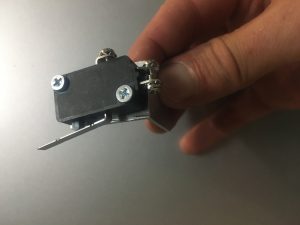
Below is a picture as it might be hard to visualize it from the description above.

Copper connector attached to switch

The curl is intentional. It reduces chance of wire rubbing against sharp edge.

Screws

Screws can rattle undone, so I applied LocTite equivalent to all screws. This includes:-

  • Bulkhead powder wells (PVC caps)
  • Bulkhead terminal blocks
  • Raven 3 PCB screws
  • Screw holding the switch right-angle
  • Screws holding the 3 x 2 black terminal block

Glue to some components

A lot of the components that are attached only have one screw. They are tightened a lot, but there is always the risk they could loosen/rotate. To reduce the chance of this, I applied a few drops of CA glue to them. The parts that had this done were:-

  • Bulkhead powder wells (PVC caps)
  • Bulkhead terminal blocks
  • MicroSwitch right-angle aluminium piece

Nine Volt battery Clip

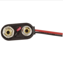
I was concerned that the 9 volt battery clip was not of sufficiently strong construction and the clip I used was recycled from another project. So what I did was purchase a replacement one from Jaycar.

Tough 9-volt battery clip

I was also concerned about the red/black wires getting into places they shouldn’t so I :-

  1. Cut the black wire to a length that meant it couldn’t possibly be a problem
  2. Applied small drops of CA glue to the red wire where I wanted it to rest, just to encourage it to stay there. It may come of in flight, but its insignificant weight means it should be okay.

The Dean-Plug

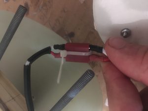
I wanted to ensure that Dean-Plug would not separate in flight. So I will install a small cable tie as shown below.

Cable-tie to keep dean-plug attached.


Wires into Raven3

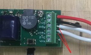
I removed a little more insulation then i should have on some of the wires that are screwed into the Terminal block on the Raven 3. As a consequences, some of the wire was visible. While it is extremely unlikely that we could have some short, I decided to cut the wire a little, to reduce the amount of bare wire showing. See the picture below.

Photo showing bare wire showing.

It is also about taking pride in the work that I do; keeping it look good as well.


SuperCap on Raven3

It is recommended that the SuperCap be glued down if the rocket is going experience high-G flights. My first flight of this rocket will not involve high-G’s, but subsequent flights may. Following instructions, I decided to apply a drop of Epoxy under the capacitor.


The Avonics Bay – Installing the Electronics

I received the Raven3 Altimeter, Shockcord, parachute bags and the RBF tag and so thought I should start installing the Avonics bay Electronics.

The thought process

Normally,  one would expect that installing the electronics would be easy to do.  Just mount battery,  mount the Altimer, run some wires using cable ties, etc. But, more thought is involved in terms of placement. So I spent much time playing around with places to put the components.

I also had to decide a few other things:-

  1. How to construct the switch
  2. What type of battery to use
  3. The type of wire to use.

Switch

I decided to use a 10amp/250volt (AC)  switch. This _should_ do the job, though I get the feeling that with DC voltages, it might not be as robust. That is okay, I will many tests to see how it fairs with setting off igniters.

Battery

I was going to use a LiPO battery, because they are so much more efficient than standard batteries. However I realised a LiPo does pose other issues. One being that I might need two LiPo batteries to supply required current and that I might have shipping/logistic issues with LiPo. So in the end, I decided to go for a 9 volt battery. I’ll probably use a Li/Mn Energizer battery (one of the blue ones).

Again, tests will tell me if my decision was a good one.

Wire

for the igniter wire, I choose wire that is rated 7.5Amps. This should be more then ample. I don’t expect it to pass this much current before the igniter does its job. I got twin wire (in a sheath). It makes for a neater job. This wire also fits inside the terminal block on the Raven 3 board. Very important!

Junction point

I wanted a 4 way splitter to allow the distribution of +9 volts to the igniters and the Raven 3. So I purchased 3×2 and used copper hook-up wire to link all three together.

Dean-Plug

I need to be able to disconnect the bulk-head without taking wire out of the terminal blocks mounted to the Bulkheads. I did this by installing a Dean-Plug. Then I’ll use a small cable-tie to ensure they don’t separate in flight.


Heat-Shrink

I wanted to guard against wires rubbing against the threaded rods and I wanted to reduce chance of shorts, so i employed heat-shrink over the rods. I didn’t bother to “shrink it” with heat, because I might want to remove them easily.


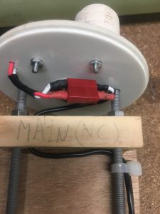
Here are some pictures of the Avionics bay

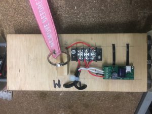
Altimeter side of the payload bay.
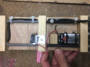
Battery side of the Avionics bay.
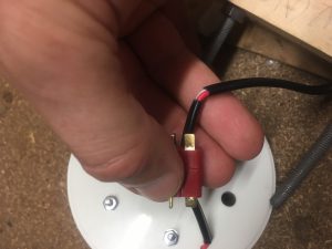
Dean Plug installed at Main Parachute end.

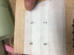
Using masking tape to improve quality of holes when drilling through plywood.

Using masking tape to improve quality of holes when drilling through plywood.

Sizing up Dean-Plug for Main parachute end.
Switch mounted to aluminium Right-Angle
Main Parachute Wiring. Notice removal of some insulation to encourage bending of electrical cable.


Here are a list of things that I did to ensure a good build:-

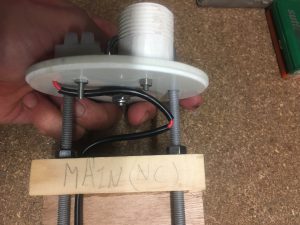
  • Put in Witness marks so I know how to assemble it back together, with everything in the right spot. This is very important for the Remove Before Flight Pin. We needed to align the Vent hole with the Pin hole.
  • The switch mounted to the Aluminium bracket is on a slight angle. This is done this way so that we have optimum lever position when pin is inserted. i.e. it is undeniably in the closed position
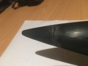
  • We have rounded the end of the pin – hemispherical. This is to make pin/switch work better
  • While the hole in the wood that the pin is pushed through is big enough for a loose fit, this hole was NOT done all the way. Part of the hole is a close fit, which means that the pin doesn’t just fall out. This is very important. We don’t want the system to be accidentally armed
  • With all screw/nuts, I used Loctite equivalent to ensure screws don’t accidentally come off!
  • For the 9 volt battery, I am using a higher quality clip, to reduce chance of failure here
  • For screw on to the switch, I’ve made up my own eye connectors using copper. I’ve bent the far end down a little to reduce chance of wire/insulation being ruined. I’ve applied plenty of solder to ensure a good connection and I’ve finished it off with some araldite to ensure that the soldered connection isn’t taking physical load.

Purchase of Parts

I’ve made another purchase of parts for my build. I have ordered:-

  • Raven 3 (70G)
  • 84 inch rip-stop nylon conical parachute, ~16 inch spill hole
  • LOC ANGEL Drogue Parachute
  • Tubular Nylon 0.5625 inch (per metre)
  • NOMEX 12×12 for up to 4 inch Tube
  • Remove Before Flight tag (Pink)

I discuss my choice of component below.

Raven 3 (70G)

Manual is downloadable from:-

http://www.featherweightaltimeters.com/uploads/Raven_Users_Manual_13April24b.pdf

This is a very well spec’d altimeter. It beeps a lot when you turn it on to alert you that things are operational and satisfactory (though many probably do)

It is a very light, small sensor. This will leave plenty of room for other components, etc inside the rocket. Unfortunately it doesn’t have a gyroscope, but there is nothing stopping me installing my own gyroscope sensor/electronics.

However it is a popular, well proven piece of hardware.

84″ Main Parachute

This has been sized to lower the rocket at approx 6ms-1. This is an upper limit. I suspect it will lower the impact speed will be a little lower. This parachute has also been chosen because it is of stronger construction, which I think will be necessary because the rocket will be travelling ~22ms-1 when it is deployed. This is fairly high speed deployment.

NOTE: Blake from AusRocketry has suggested that using a LOC ANGEL parachute (large?) would do the job well and might be easier to pack into the parachute bay. Using the calculations on the webpage with known weight of the rocket, we would be looking at a decent speed of about 5 ms-1.

LOC ANGEL Drogue Parachute

I really wanted to get a 28″ or 30″ Drogue, but they seem hard to come by. This is a 24″ drogue and checks have shown that it SHOULD reduce the speed of the rocket to about 22ms-1. If I see/learn of reasons for a major deviation upwards, will need to consider purchasing an alternative Drogue Chute.

NOMEX 12×12 for up to 4 inch Tube

This is wrapped around the Parachute to protect it from the exhaust gases. I expect that this will be attached to the shock-cord, so we don’t lose it at ejection.

I got two of these, one for the Drogue, the other for the Main parachute.

Remove Before Flight tag (Pink)

I’m going to have ONE switch to turn everything on/off.  I didn’t really want Pink coloured one, but there weren’t many others.

Later I convinced myself that Pink is just fine, infact it is highly visible and should be no missing it!


Acquiring Explosives Licence

Why I need to Acquiring Explosives Licence

To obtain my L2 Certification, one thing I need to get is my Explosives Licence. For obtain this, I needed to get a letter from my Model Rocketry club in relation to my gaining L1 certification.

It is a  slow process, but important one.

One of the things I need to do is perform some ground tests, sizing the ejection charges. To obtain the powders to do this, I’ll need the licence.

For other people who wish to do their certification, their club should be able to assist in details of acquiring a licence.


Shear Pin Calculations

I decided to spend a bit more time analysing Shear Pin Requirements for the ejection systems. I felt I needed to understand what I am trying to achieve, what the pitfalls are before going out and installing something that probably will work, but without the knowledge of knowing how well it will work (if it does work).

Things we need to know

The specific material used in Shear Pins I have purchased from AusRocketry. I know they are Nylon, but what type of Nylon.

  1. The strength rating of these Shear pins
  2. The Pressure differential at Apogee for various flight profiles.
  3. Diameter (min, pitch) of the Shear pins I have
  4. Dimension of the rocket cavity
  5. Where the Shear Pins need to be installed.
  6. The number of shear pins for the Drogue Chute
  7. The number of shear pins for the Main Parachute

Figuring the above things out

Strength rating of Shear Pins

We don’t know the Strength rating of the shear pins. We can take guess that they are between  9600 to 10500 PSI. We will need to confirm this.

I did some very elementary tests on a single nylon screw using brick-layers thread and rectangle angle and luggage weigher. I did two tests

  • Atleast 15kg at last look
  • Atleast 11kg at last look

with the second test, it didn’t shear the screw, but instead pulled it through, so I consider this test to be some what unreliable.

The loading was also slowly applied and this might have led to change in properties. In summary, very hard to test. These tests just give us a very “basic” idea of testing. To test properly I would have to get some fiber-glass and install as they will be. Probably need to have three shear pins as well.

15kg translates to about 33pounds. This is close agreement to the theoretical calculated max shear stress of 14kg calculated below.

The Pressure Differential

We need to consider the TWO areas of the flight where the Ejection charge are going to be ignited. One at Apogee and one ~200metres above launch area.

We will assume that the flight is at altitude that is fairly close to Sea level, so that for all intensive purposes, Air pressure at found = 101325Pa.

We use the Air Pressure Calculator – https://www.mide.com/pages/air-pressure-at-altitude-calculator with :-
Pressure at Sea Level: 101325Pa

Temperature: 25 degrees C

Apogee – Drogue Chute (L2 altitude = 1200m)

For the most powerful motor, we expect an altitude of approximately 1200 metres. This means an air pressure of 88146 Pa.

i.e. Differential Air Pressure is 13,179 PA. This is 1.9PSI.

Apogee – Drogue Chute (max altitude)

For the most powerful motor, we expect an altitude of approximately 3500 metres. This means an air pressure of 71010 Pa.

i.e. Differential Air Pressure is 30315 Pa. This is 4.4 psi.

200m – Main parachute

At 200metres above, when the main parachute is deployed, the air pressure is 99024Pa.

i.e. Differential Air Pressure is 2301 Pa. This is 0.3 psi.

Diameter of Shear Pins

Preliminary investigations suggests the 2/56 shear pins will be the most suitable shear pins for this flight. So we only consider these.

AusRocketry has outer thread size being 2.184mm

Feretich web-site has:-

Major diameter: 0.0860″  (2.1844mm)

Pitch Diameter: 0.07440″ (1.890mm)

Minor: 0.06410 ” (1.630mm)

This agrees with what AusRocketry says. i.e. outer thread = Major Diameter.

Rocket cavity

We need to consider both cavities separately.

Lower cavity – Drogue Parachute

Length: 740mm (29″)

Diameter: 99mm (3.9″)


Upper cavity – Main Parachute

Length: 400mm (16″)

Diameter: 99mm (3.9″)

Where the Shear Pins need to be installed.

Two installs of shear pins need to be performed. One at the Nose cone between the Nose cone coupler and the payload Air-frame AND one between the Avionics bay and the Booster Air-frame.

Each set is X # of pins (probably 3), 30mm set from edge of the air-frame ends , each hole equidistant from each other.

NOTE: It is possible that each set will have different number of shear pins. We will see.


Requirements of set-up

  • Work on L2 flight
  • Work with other flight profiles (> altitude than first L2 Flight profile). With L1395-BS (Total Impulse 4895), we have a flight altitude of ~3.3kms.  So we decide that peak altitude we can safely fly the rocket is 3500metres
  • Be able to stop premature separation
  • Be more than capable of separation of components without blowing them up.


Calculating Shear pin Loadings

Both shear pin installs need resist the pressure differential at Apogee.

We assume that the cavity does empty/fill with air as it travels its flight.  This is not strictly 100% valid, but should be close to it as we are depending upon this for our altimeter to give the controller the data it needs to know when Apogee is reached and later on when we are 200metres above the ground.

Let’s calculate the shear force that the pins can resist. Let’s consider the worst case scenario -lowest strength, minimum diameter

Minor Diameter: 0.06410 ” (1.630mm)

Minor Area: 2.09mm^2 (0.00323 square inches)

Shear Strength: 9600 psi

Force = Pressure * Area = 9600 * 0.00323 = 31 Pounds Force (lbf)


Now let’s calculate the force to perform the separation, focusing on the worst case scenario – highest strength, maximum diameter

Pitch Diameter: 0.07440″ (1.890mm)

Major Area: 2.81mm^2 (0.00436 square inches)

Shear Strength: 10500PSI

Force = Pressure * Area = 10500 * 0.00436 = 46 Pounds Force (lbf)

NOTE 1: 1 pound force = 4.45 Newtons and to convert 4.45 N to equivalent mass at sea level (to exert this force), we divide it by 9.81. 1 pound = 0.454 kg. So 31, 46 pounds force translates to 14 kg, 21 kg


Keeping the components together

The altitude for this flight is 1200m. At this altitude, the air pressure drops by 1.9PSI

Let’s assume that the air does not escape in time. This is obviously worst case scenario, but let’s do this. We need to consider both sections held by Shear Pins.

Area of cavity = pi * (d/2)^2 = 3.1415 * (99/2)^2 = 7697mm^2 = 11.9 square inches

L2 FLight

So the force due to the reduction of air pressure (worst case scenario) is:-

F = P x A

= 1.9 * 11.9 = 22.6 lbf

If we have three Shear Pins, then the maximum force they can resist (without any safety figure included) is 3 * 31 = 93 lbf

If we have a 25% safety margin, this brings allowable load to ~70 lbf

70 lbf > 22.6 I – So three shear pins is more than ample.lbf

3500 metre flight

Now lets consider the scenario with the more powerful motor.

F = P x A

= 4.4 * 11.9 = 52 lbf

70 lbf> 52  lbf- So three shear pins are is still more than ample.

Ejection

L2 Flight & 3500 meter flight

We want to know how much PSI we need to be sure that the ejection will succeed.  i.e. we want the the PSI to exceed the rating of the shear pins. We also need to have sufficient force to ensure we overcome friction of fittings and any other losses

With three pins, the Force required to break three shear pins is 3 * 46 = 138 pounds Force.

Now, let’s round this to 150 pounds force. This should be sufficient to take into account any losses and additional forces keeping components together

P = F / A = 150/11.9 = 12.6 psi

NOW, if the air doesn’t equalise completely, then we will have even greater PSI differential = less chance of separation not occuring.

Things to note:

  1. The same PSI differential is required at both Drogue chute and Main parachute deployment. There is less likely to be a pressure differential at the Main Parachute deployment because there is more time for the air to equalise.
  2. There should be no real difference in charge required between the L2 and 3500m flight…yes there might be greater differential for the 3500m flight, but this will be working in our favour.


 Selecting a suitable solution

So we select:-

  • 3 * 2/52 Shear pins for Top (Main Parachute) configuration
  • 3 * 2/52 Shear pins for Bottom (Drogue) configuration


Other thoughts

We can’t just leave it here. I have been bias against just two shear pins because of my concern that it might get stuck. Perhaps these concerns are unwarranted.

If we have sufficient quantity/size of vent holes, we can probably safely assume that there is significant equalisation which means the force pushing off the nose cone isn’t so great. This would mean we might only have 1/2 equalisation (guess)

F = P x A = (4.4/2) * 11.9 = 26 lbf

So with two shear pins supporting 2 x 31 = 62 lbf which with a 25% safety factor equates to 46.5lbf

So the force applied here due to air pressure differential is significantly less than the greatest force the pins can resist.

The bonus of this we can probably go for less Black Powder. If the maximum force they can resist is 62 lbf and we add 25% safety factor , this translates to 77lbf.

P = F / A = 77/11.9 = 6.5 psi.

Using:-

http://www.rimworld.com/nassarocketry/tools/chargecalc/index.html

For the large parachute, it is very well packed and will probably need a bit more force than the drogue to eject. So we got for 150lb of force.

We get :-
Tube Diameter (in): 3.9
Tube Length (in): 16
Desired Pressure (suggest 8 to 15 psi): 12
Grams of 4F Black Powder : 1.18 grams

and

We get :-
Tube Diameter (in): 3.9
Tube Length (in): 29
Desired Pressure (suggest 8 to 15 psi): 11
Grams of 4F Black Powder : 1.97grams   … round to 2 grams.

This is still giving us a lot of extra margin – because we are producing 8psi of high pressure gas, rather than the 6.5psi, which is already 25% above what is needed to break the two shear pins.

I just need to convince myself on the wisdom of having two shear pins over three.

Eventually I decided to go for 3 shear pins.

Resources

Three very hand sites :-

  • Discussion on Shear pin selection with calculations – http://www.feretich.com/Rocketry/Resources/shearPins.html
  • BP Charge size Calculations – http://www.rimworld.com/nassarocketry/tools/chargecalc/index.html
  • Air Pressure Calculator – https://www.mide.com/pages/air-pressure-at-altitude-calculator
 

Sanding the Nose Cone

The Nose cone is moulded plastic.

Nose Cone Tip issue

I discovered after gluing the bulkplate in place that the tip was not 100% fixed, but could be rotated. I could apply a parting force and there was a very small gap (0.25mm). This gap was not all the way around the piece. So unfortunately I should have tightened this up before hand. Cursing myself somewhat.

So what I did was apply CA glue inside the gap between the nozzle tip and the remainder of the nozzle. It is not fixed and won’t move/rotate.

Nose Cone tip bonded to Nose Cone using CA glue.

This I think should be satisfactory for flight. I’ve posted a “post” to AusRocketry Forum to get their input. If not okay, I’ll probably need to purchase replacement parts.

The initial thoughts from posters on AusRocketry Forum is that it should be okay – but I will need to check this post-flight, to see if any movement. Movement is most likely due to impact with the ground.

Sanding the Nose Cone

I’ve started sanding the nose cone, trying to remove the ejection mould hang-overs. I’ve used Grit-60 Sandpaper to remove these. Some bits were so bit that I used small pliers and Exacto Knife to remove the bulk of them.

Then I used Grit 240 sandpaper to sand it down.

It is pretty smooth, but I can still fill steps using my nail. I might wait until I apply Primer before I do any more sanding.

Nose Cone Bulk Plate

Next step was to attach the Nose Cone Bulk Plate.

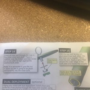
I follow the instructions carefully.

Instructions
Instructions

I used :-

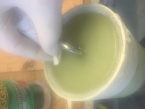
  • 24 Epoxy for the initial join. IT is sufficiently viscous that it won’t run between cracks. It is also stronger than 5 minute epoxy.
  • 105/206/403 Epoxy mix for the fillet. It is something I’m very familiar with, has a lot of strength.
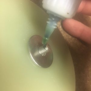
  • LocTite like solution for bulkhead screw.

Assembly of the Bulk Plate


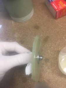
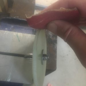
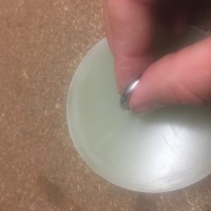
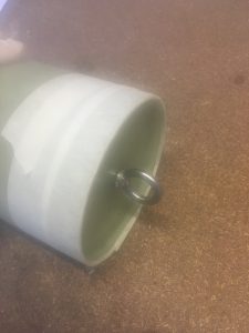
Below are some pictures of me assembling the Bulkhead with Ring bolt.

Applying LocTite Equivalent to thread.
All screwed up tight.


Epoxy the Bulk Plate into Nosecone Coupler

First step was to sand the surfaces ready for epoxy. I also sanded areas of bulkplate that would have fillets.

Sand external rim of bulkhead.
Sanded outer flat section, where fillet will be.

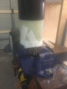
After I applied epoxy to bulkhead rim and inside the nose cone coupler, I slid the bulk head in. It slipped a little and initially I struggled to keep it fixed the SAME distance from the end of the coupler. So what I did was cut some 5mm tube that I had used for Epoxy delivery and curled it inside the recess.  I used masking tape to keep it in place.

Taped up with 5mm tube to help hold bulkhead at correct distance from end.

Then I put it in a vice, to allow the epoxy to settle down and form a strong bond.

Set-up in vice.
Set-up in vice.

After two hours I removed it from the vice and removed the plastic tube. It was easy to move and I didn’t upset the bulkhead position. Then I left it for another 4 hours before doing any more work.

The fillet

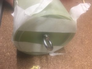
Then I went about taping it up. I’m very particular about creating minimal amount of work (i.e. mess).

Taped up so we don't get epoxy where we don't want it!
Taped up so we don’t get epoxy where we don’t want it!

Notice how the masking tape also encroaches on the inner part of coupler, down about 2 mm. This is to try and minimise mess, minimise epoxy getting where it shouldn’t.

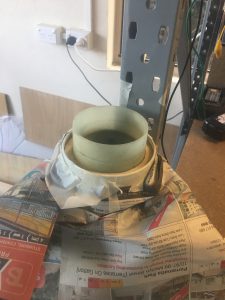
Then I made up the 105/206/403 epoxy miss and used a syringe to get it into the edge. I applied this in the usual way and then I used a small plate like tool to create the fillet. A few minutes after done, I removed the tape.

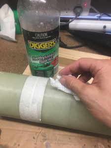
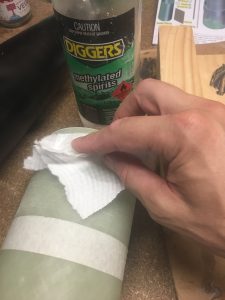
Before leaving it to cure, I cleaned the bulk-head using paper towel and methylated spirits.

Removing excess Epoxy using paper towel/Methylated spirits.


Centering Ring – Fillet

I now need to create a fillet on the rear centering ring. This was particularly difficult to do because the Motor Mount tube is in the way. I could have done a simple dump of 24-Hour Epoxy and created a circular ring of epoxy. This would have looked aesthetically pleasing, but would be excessive amount of weight. So I decided to got for 105/206/403 mix and use my finger to try and create a fillet (inner and outer). Unfortunately it wasn’t terribly even/pretty, but it certainly adds strength to the join. Below are some pictures of the work.
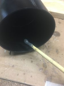
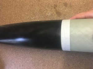
Taped up and covered areas with paper - to keep surface free of epoxy.
Taped up and covered areas with paper – to keep surface free of epoxy.


Tape inside airframe to ensure we have a recess - for the AeroPak Tailcone.
Tape inside airframe to ensure we have a recess – for the AeroPak Tailcone.


Epoxy ready for Centering Ring Fillet.
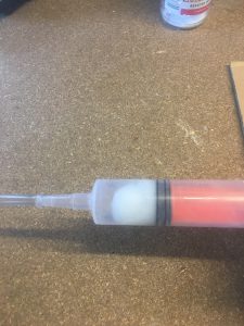
Epoxy in Syringe, ready for applying to CR Fillet area.
Epoxy applied
Epoxy applied

Used my pinky finger to create the fillets  on Motor mount and air-frame. It wasn’t perfect or pretty, but it will be strong.

Gluing Switch Ring on Payload and Nose Cone Coupler

Need to glue two more components –

  • Coupler to Nose Cone
  • Switch Ring to Payload Coupler unit

Used Bob Smith Epoxy to attach them. BS Epoxy is easy to spread and because we only need a thin film it won’t drip and make a mess like some epoxy, e.g. West Systems.


The Payload Switch Ring

Below are pictures of Payload Switch ring.

Checking, double checking that the place where the Switch Ring is to be glued is the right spot. Tape is reduce amount of Epoxy getting into places I don't want it to go.
Checking, double checking that the place where the Switch Ring is to be glued is the right spot.
Tape is reduce amount of Epoxy getting into places I don’t want it to go.


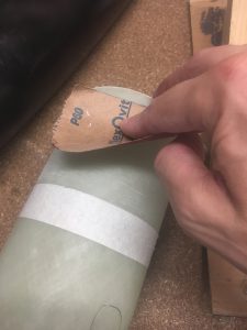
Sanding section where Switch Ring is going to be glued.
Cleaning payload coupler prior to gluing with Metho.
Mixing up BS Epoxy for Payload Switch Ring.
Applied Epoxy to Payload Coupler, to where the ring is going to sit.

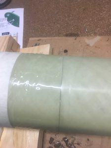
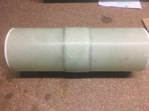
Then we just slid the Switch Ring on, wriggling it a little to ensure thorough epoxy across both surfaces.

Finished bonding of Switch Ring to the payload.


Nose Cone – Coupler

Masking taped up just area, so when epoxy, reduce chance of it going where I don't want it to go.
Masking taped up just area, so when epoxy, reduce chance of it going where I don’t want it to go.
Sanding coupler with Grit-60 Sand paper.
Cleaning surface before bonding with Metho.
Applying Epoxy to inner section of Nose Cone
Glued together - just before I removed the tape.
Glued together – just before I removed the tape.


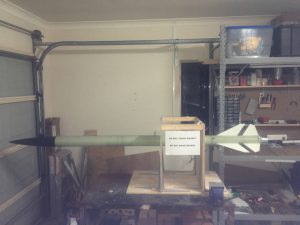
Assembling the rocket

Rocket - all assembled.
Rocket – all assembled.

Gluing on the Retainer top the Motor Mount

Next step was to glue the Motor retainer on using JB-Weld.

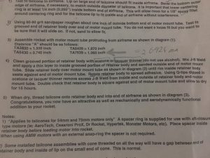
We followed the steps that were on the AeroPak TailCone. The last two in the screenshot below.


Instructions to install retainer.


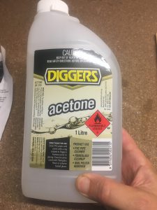
We needed to use Acetone to clear the internal threads of the retainer component we wish to epoxy to the Motor mount.

Acetone used to clean internal thread of retainer


Cleaning thread of Retainer

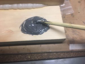
Once clean, we make up a generous amount of JB-Weld and mix thoroughly.

Making up batch of JB-Weld for retainer.


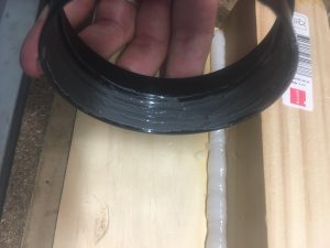
Creating a nice thin film of JB-Weld. Getting it into the grooves.


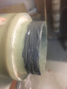
Once done, we add a generous amount of JB-Weld to the motor mount, making sure to keep it to the area that the retainer is going to slide up to.

Getting good coverage of JB-Weld over the Motor Mount.

Then I slid the adapter on. As I slid it on, I turned it around a little, back and forward, in and out to ensure that the JB-Weld Epoxy made good contact.


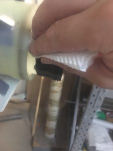
Cleaning off excess JB-Weld

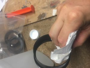
I removed excess JB-Weld inside and outside using paper towel and Acetone.


Cleaning off excess JB-Weld

I checked all around the rocket to see if there was any stray JB-Weld. I made sure that the adapter was butt up against the Motor Mount.

Checking for any JB-Weld to clean off

I left it overnight to dry.