All posts by joeadmin

Final Preparations for Launch 4

Final preparations are being made for Launch 4 which we hope will take place tomorrow, weather permitting.

The Weather

The wind speed is going to be approximately 10 to 15 knots. We don’t really want to fly if more then 15 knots. Rain is 50% chance which sounds bad, but this is over a large area, so it probably a lot less chance then 50%. We will check the radar before we leave to see what is about. We’ll also check the motion of the trees on the mountain next to where we live as they will provide us a good indication of wind speed.

The motor

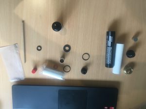
I have assembled the G76-10 motor. This included reducing the delay from 10 seconds to 6 seconds using the AeroTech tool. One thing I have not done is install the igniter. I want to do that on the day just before launch. The igniter is delicate and I think it is bad practice to install igniters until one is ready to launch.

Here are some pictures of the assembly.

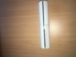
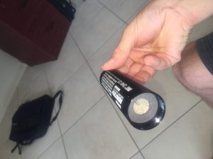
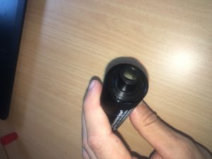
All the parts of G76-10 laid out
Aft Cap with delay charge with 4 seconds removed.
Two grains assembled together
Grains inside AeroTech Case with insulator at top
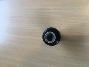
Nozzle of motor before brass cap screwed on.

Batteries

All batteries have been charged, even if I thought they were okay. I found that the igniter battery was completely flat! Very glad I checked this. This could be because the voltage measuring resistors have flattened the battery. I will leave this disconnected from now on, unless I’m going to sue it.

Test Ignition

I put a high value resistance resistor as the igniter and I was able to perform ARM, CONTINUITY TEST and a trial ignition. I measured a voltage of 12.5 volts across it. Great!

All the Parts

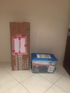
I’ve gone over the checklist and packed everything away.  Ready to go. Also packed the rocket in its delivery box with lots of padding. I decided to roll up newspaper and put in aft and rear of motor to stop rubbish getting in. Before doing this I folded up the parachute and inserted it in as carefully possible. We will need to tie the cord to the bottom of the electronics bay payload before launch.

Everything packed away and ready for launch day.

Last minute Check

I confirmed the steps for the payload turn on. I’ve also got some Masking Take (from my very generous and helpful friend – Alex). This will be used to ensure no shorting of jumpers


Our Model Rocket launches At QRS in January

This post is a little late, but still worth getting out.

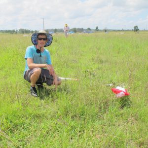
On the 10th of January 2016, myself, Anna, Jeremy, Isaac and “Grandpa Val” travelled to the Goldcoast to attend a Queensland Rocketry Society Launch day. We all got to fly a rocket! Even Anna did!

Isaac’s Rocket

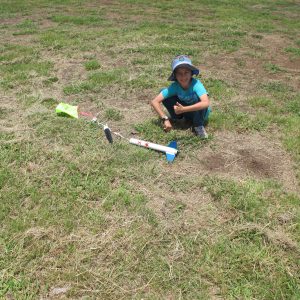
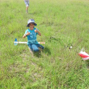
Isaac flew a Small 15 Gram model rocket with a B-Engine. He was initially very scared of the noise and wanted to sit further back with the cars. Eventually he got the courage to participate in the rocket launching. Very pound of you Isaac!

Here are some pictures of Isaacs rocket and the boy himself!

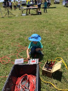
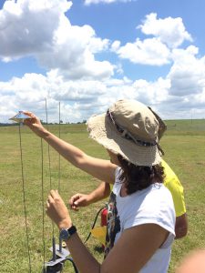
Isaac hecking the continuity of his rocket launch line


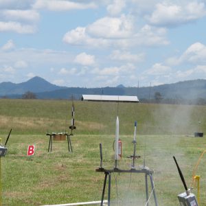
Isaac's rocket is one with blue nose cone
Isaac’s rocket is one with blue nose cone
Isaac with his Grandpa
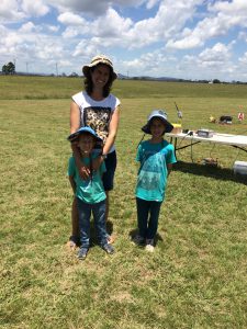
Three rocketeers!
Three rocketeers!


Jeremy’s Rocket

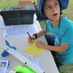
Jeremy’s rocket is an exceptional rocket for a first timer. This rocket had a D-engine expertly installed by Blake (Owner of Ausrocketry). It deployed its parachute perfectly! Lovely work Jeremy!

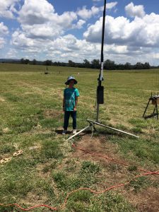
Jeremy with his rocket on launch pad
Jeremy recovers his rocket - all intact!
Jeremy recovers his rocket – all intact!
Jeremy filling out his launch card

Anna’s (Mummy) Rocket (UFO)

Anna couldn’t miss out on the action and launched a UFO rocket. This had a C-Engine in it. It flew really well!

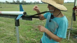
Anna carefully setting up her 'Rocket' for launch.
Anna carefully setting up her ‘Rocket’ for launch.


Joe’s L1 Attempt

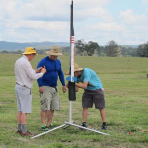
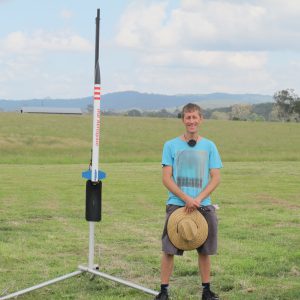
Well I decided to go for my L1. This was very exciting. It took a lot of time to set-up the engine, even though it was just a CTI engine! I was taking things very carefully. Didn’t want to make any mistakes.

Inspecting the business end.
Jeremy standing next to my rocket where it landed
Found my rocket. All perfectly intact and only about 100 metres from launch pad.
Setting up the Ignitor
Ready for launch photo shoot.
Successful parachute deployment

What a great day!

Preparations for next model rocket launch

A lot of work has been done constructing the payload and programming the micro-controller. Preparations are now underway for the next model rocket launch.

Below is a picture with everything assembled.

Payload assembled into Rocket

The payload airframe section (the grey section in the above picture) will be painted white. Read on to find out more about the payload and what it can do.

Payload

The launch will have an experimental payload included on it which will:-

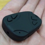
  • Capture Video of flight at 720 x 480 with sound using a 808 keychain camera
Surveillance Camera
Surveillance Camera
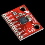
  • Capture and record gyroscope data (rotational speed) using a L3G4200D breakout board
Gyroscope sensor
Gyroscope sensor
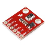
  • Capture and record air pressure and temperature measurements using a MPL3115A2 sensor
i2c based MEMS  Air Pressure sensor
i2c based MEMS Air Pressure sensor


The final payload (before sliding into air-frame) looks like:-

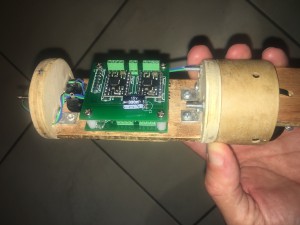
Front view of payload tray

The sensors are sandwiched between the PCBs and the battery board. Space really is a premium.

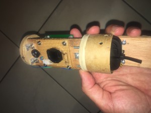
Back view of payload

Notice the coin cell batter and the rotary switch on the LHS and the camera on the RHS. The rotary switch is accessible from the outside.

Payload Data

It is certainly an ambitious project, but hopefully will produce some results that will allow us to characterize the motion of the rocket as well as test our payload design and operation. The Air Pressure results will allow us to approximate the altitude of the model rocket over the flight which we will then be able to compare to our simulations. The gyroscope readings will be very interesting when we compare with video recorded motion of the rocket. Temperature will be interesting, but is of less importance.

I’ve created a video that allows us to compare the ‘real world motion’ of the payload when compared with the motion depicted using the gyroscope data. See below.


The Rocket Motor

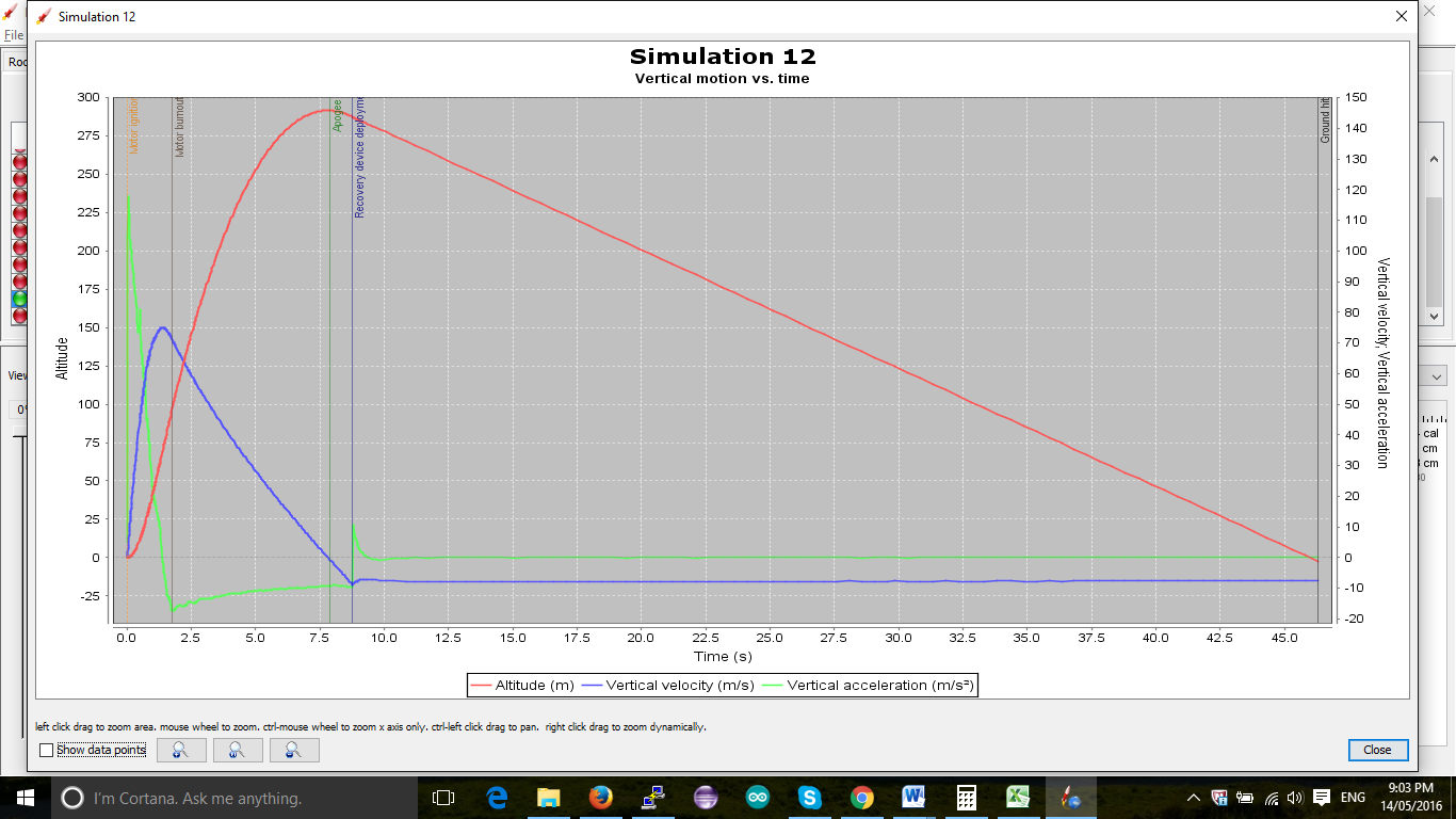
We will be utilising a G76-10G Aerotech engine. This translates to an average thrust of 76 Newtons over the total burn time of approximately  Below is a plot from OpenRocket.


Simulation of launch

As you can see, this rocket will achieve an altitude just shy of 300 metres. (less then 1000 feet). This is well short of the 4000 feet ceiling we have at our launch site. We still expect the launch to be spectacular.

Remaining Preparations

Remaining preparations include:-

  • Generating Launch simulation to ascertain key information like ejection delay, speed of rocket off the launch rail
  • Confirming CG and CP points (checking stability of the rocket)
  • Confirming launch location suitability and timing
  • Checking and testing launch Electronics systems
  • Charging batteries
  • Performing inventory check and packing boxes with required items
  • Writing and testing procedures
  • Double checking motor risks (issues that other people have recognised with the motor). The AusRocketry forums were helpful in this respect.


Air Pressure and Temperature Sensor

It was decided on a whim to purchase and install a Air Pressure + Temperature sensor for the next flight. I purchased a :-

http://core-electronics.com.au/search/?q=MPL3115A2

I picked this because the pins were arrange in same order as the Gyroscope pins. So I had a relatively easy job of just soldering this on top of the Gyroscope.

Programming wasn’t as simple. The libraries that you can get from AdaFruit or SparkFun generally are one-shot, in that you need to wait a significant time for the sensor to return a value (in the order of a second). This is not satisfactory because we need to capture as much gyroscope data as possible. So we looked into a demo Arduino program by Sparkfun called SparkFunMPL3115A2AdvancedExample.ino. In this example it would get the sensor to collect data autonomously and at the end it would fetch all the data. It utilises a FIFO that can store up to 32 measurements of air pressure/temperature. We programmed our sensor to collect data every second. We allowed sufficient time at the end of the~8 seconds of gyroscope collected data (FRAM memory only has enough space for ~8 seconds of data) to get another 24 data points, by employing a 24 second delay. This should allow us to get 32 seconds (~ 3/4 flight profile) of air pressure and temperature. The program then stores this data at the very end of the FRAM.

We then modified the dumpFRAM routine to process the air pressure/temperature data to allow us to see what was recorded!

I tested this out by running up the hill with the sensor. Sure enough, the air pressure reduced as I ran up the hill. This extra sensor is a great addition to the flight. It will allow us to approximate the flight altitude over time, allowing us to compare it with the predicted flight altitude over time (generated from Open Rocket).

Below is an extra from a dump from the routine dumpFRAM.

2 151 79 32
RS: 0.02, -1.14, 0.01
2 151 115 216
RS: 0.03, -1.25, 0.07
2 151 152 144
RS: 0.02, -1.22, 0.02
2 151 189 72
RS: 0.04, -1.26, 0.11
2 151 226 0
, Temperature = ,26.7, C, Pressure = ,101.41, kPa

Here RS means Rotational Speed

The other lines with 4 numbers can be combined to produce the time in microseconds

At the end is the Temperature and Pressure. These are ~1 second apart.

Creating the Payload Bay

We are creating a payload bay that will house the electronics and ultimately all the rest of the hardware. For now, we only require it to take the electronics, which will be all that is needed for the first few flights, to obtain sample data from the Gyroscope. We are leaving enough space so that we can later install stabilisation motors.

This of course is a smaller, cutdown version of the ultimate rocket we wish to launch. However, we want to get a smaller version of this rocket Stabilisation system working on a small one. A proof of concept.

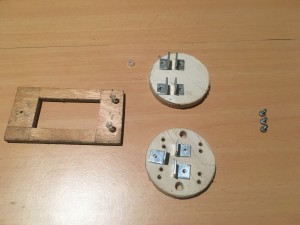
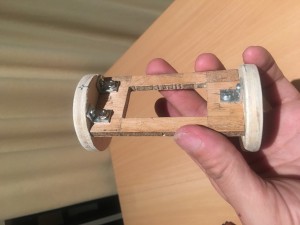
Here are components that make up the electronics bay (just one part of the payload).

Payload tray on left, top payload tray cap above and bottom payload tray cap below.

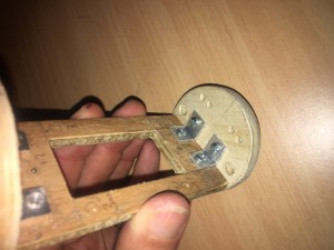
Below are some pictures of the payload bay, partially constructed.

View of partially built payload bay


A rotatary switch will be installed between the top two brackets. Holes will be drilled on either side of the tray, to which we will attach the PCB. Some of the PCB breakout boards will actually sit within the cut-out in the tray. i.e. this cut out is more then just a weight saving measure.


Looking down at bttom plate of payload tray. Notice holes for cable ties, electronic cables and fixing screws.


We hope to get the electronics components later in the week and start building and attaching to the payload tray. We will provide a new Post when this is complete.

Prototype of Stabilisation system

A lot of progress has been on the stabilisation system. We have managed to:-

  • Get the Stepper motors working in 1/4 steps. We needed 1/4 steps because full steps were causing vibrations and we would miss steps.
  • Use Interrupts and clever coding to calculate (and buffer, using a Ring Buffer) timing values. We didn’t have enough memory to store timings in array and we could calculate just one time interval per step.
  • Managed to implement Hall Effect sensors to detect when Smoothers are close to pre-determined position. This allows the system to calibrate the smoothers, i.e. move them into an initial starting position.
  • Managed to get the Gyroscope working error free. We did this by getting to to check the status register to confirm data has been written to the registers. We also implemented a single Wire Read to get all the gyro data, rather then individual reads. This should give us extra cpu cycles while the stepper motors move. Very very critical!
  • We calculate HIGH/LOW values for X, Y, Z. We also calculate average and variance of these values. We use the high/low values for x, z axis to set the values to Zero, should they fall within the range.


Below is Youtube movie of the system being testing. The video was slowed down because the smoothers move so fast, one cannot pick it up with ones eye!


Simulating a Stabilisation System

We decided to create an application to produce two simulations. Each simulation would be of a rocket that has a moment due to the centre of mass not being quite on the main axis

  • In the first simulation there is no guidance system
  • The second has an active guidance system.

The guidance system’s sole purpose is to reduce rotational speed. It does not attempt to keep the rocket pointed ‘up’.  [We do envisage at some point, some attempt will be made to have a stabilisation system that can attempt to counter the drift in direction of the rocket].

The video simulations are best watched in full-screen mode as the rocket is quite small. It is small because we positioned the viewing platform a large distance from the rocket, so we could get a good view of the majority of its launch.


The specifications of the rocket are:-

Engine: Single D engine

Rockt Length: 584mm

Rocket Mass: 221 grams

Guidance System: KATE [Kinetic Attitude Thrust Engine]

Location of Guidance System: 250mm from tail


The code that was used to produce this simulation is freely available at:-

https://github.com/joeman155/JJROCKET_SIMULATIONS

The KATE System

The is the name that has been given to the system to provide stabilisation. It will be described in detail in future posts.


How to keep a rocket Pointed up when Launched from a Balloon

Keeping a rocket pointed up when launched from a balloon is not an easy feat. Countless hours of thought have been put into this and several ideas have been considered and then dismissed. Some of these ideas are presented below.

Have a rocket with Long Launch Rod

Can we use a launch rail, like we do on Earth?

No.

We need to first realise that while there is very little air at an altitude of 30km, there is still sufficient air to allow stabilisation using fins. This is provided we are travelling fast enough. The reduced air density means that the velocity required is substantially more then at sea level.  This means we would need a longer launch rail to ensure that the velocity is sufficiently great when it leaves the rail tip. Let’s consider the equations that give us lift.

Lift = Cl * density x Velocity ^2 * Area/2

Density of Air at sea level is 1.225 kg/m^3

Density of Air at 30km is  is 0.01841 kg/m^3

Let’s assume that 20ms-1 is the minimum velocity required at sea -level. With this we can estimate the minimum speed required at an altitude of 30km

velocity = sqrt(density-at-sea-level * velocity-at-sea-level^2/density-at-30km)

= 163ms-1

Let’s assume the rocket is accelerated at 10g  (98ms-2) up the rail.

v = a * t

t = 163/98 = 1.66seconds

s = 0.5 * 98 * 1.66^2 = 135 metres

This is clearly impractical. The launch rod would be very long, heavy and unwildy. We would need a massive balloon and someway to stabilise the rod. Then we would have the issue of the launch rod coming back to Earth. Totally out of the question!

Spin stabilisation

Another option considered was spin stabilisation, where by we attach rockets to the side to spin it up. This makes the rocket act like a spinning top. Simulations have been done to see how attaching two D-engines to a rocket, to see how fast it will get and how much the spin is affected when engines are slightly mis-aligned. Unfortunately. even with very small manufacturing tolerances there is sufficient wobble to cause issues. We tried to increase the Moment of Inertia in in some axes to reduce the amount of rotation in those directions, however this adds alot of extra weight which is extremely undesirable.  There is also the problem of how we suspend the rocket when we spin it up, or if we have to release the rocket and then spin up.

This solution is extremely unpractical and complictes the launch sequence considerably. There a lot more possible modes of failure.

We have decided against this option.

Thrust Guided Rocket

The idea here is that one can either:-

– Move the nozzle, which will adjust the thrust direction

or

Move some vanes that are downstream of the thrust that re-direct the thrust direction

With the solid engines, the former is inpractical. The nozzles are fixed.

With the latter, the design is not simple, or easy to simple and some of the engineering required is not so simple. We would need some external actuators, ones that can provide a massive torque (to combat the force of the rocket thrust), while still keeping the rocket streamline, and at the same time using the limited ‘realestate’ at the bottom of the rocket. For the vanes, we would need special material that would not be destroyed by the thrust, be light and have a specific design to induce the right sort of adjustments.

We have decided against these two options.

Centre of Mass Guided Rocket

This is not a commonly used method, however, it has been mentioned a little in some of the rocketry literature on the Internet. The concept is that you adjust the Centre of Mass (moving it laterally) so that the thrust, in combination with this off-axis centre of Mass produces a resultant moment.

Imagine yourself standing up and someone pushing you backwards. You instinctively put your arms/hands outreached in front of you to try and move your Centre of Mass forward.

This method could work, but it would need to move masses quickly and efficiently without producing too much un-wanted disturbances to the rocket’s motion. The whole system would need to be relatively light, so as to not be a burden on the rocket.

Summary

The latter option seems the most likely to succeed. We have decided to put a more thought into such a solution. In particular, we decided it would abe a good idea to try and simulate such an engine.


First launch of JAJI Rocket

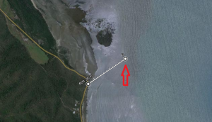
A launch of the JAJI rocket was done on the 1stof November 2015 at the mud-flats situated approximately mid-way between Palm Cove and Port Douglas.


Launch location
Launch location


It was an extremely hot day to launch the rocket. I had to walk about 8km in total to get all the equipment out to the launch area. I got a lot of blisters. I will definitely be trying to work out a better way to get the launch site setup next time.

Eventually we got everything setup, but then had some issues with the GroundStation Electronics. The groundstation.pl process kept finding non-ascii characters and crashing. As a result we almost didn’t get to launch the rocket. We managed to get through all the stages of the launch sequence by restarting the Groundstation between each step.

We have since discovered the cause of the Groundstation issue. It was due to overflow of the Serial Buffers. We’d lose some data and we’d get ‘pieces’ of data. This totally confused the groundstation perl script and crashed it. One improvement that we are looking at implementing is a re-start on crash script. Other improvements include ensuring Serial Buffers cannot be overflowed.

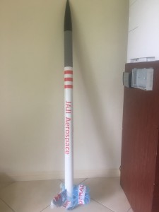
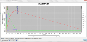
The engine we used was a HP110-G250VM-14A and the rocket we used was ‘JAJI AEROSPACE’, a Callisto rocket. We used OpenRocket to predict the speed and altitude. These are below.


OpenRocket_Launch_Simulation
Graph of altitude, velocity and acceleration


Summary information
Summary information


A video of the launch is below.


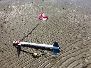
Below is a picture of the landing.

Rocket Landing site - Notice the imprint of the motor in mud
Rocket Landing site – Notice the imprint of the motor in mud

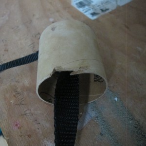
The piston was slightly damaged by the shock cord. See a picture of this damage below.

Damaged Piston Tube
Damaged Piston Tube

This damage is minor. It was repaired using some areldite and masking tape. Then it was sanded down so it could easily slide up and down inside the airframe.