I decided to spend a bit more time analysing Shear Pin Requirements for the ejection systems. I felt I needed to understand what I am trying to achieve, what the pitfalls are before going out and installing something that probably will work, but without the knowledge of knowing how well it will work (if it does work).
Things we need to know
The specific material used in Shear Pins I have purchased from AusRocketry. I know they are Nylon, but what type of Nylon.
- The strength rating of these Shear pins
- The Pressure differential at Apogee for various flight profiles.
- Diameter (min, pitch) of the Shear pins I have
- Dimension of the rocket cavity
- Where the Shear Pins need to be installed.
- The number of shear pins for the Drogue Chute
- The number of shear pins for the Main Parachute
Figuring the above things out
Strength rating of Shear Pins
We don’t know the Strength rating of the shear pins. We can take guess that they are between 9600 to 10500 PSI. We will need to confirm this.
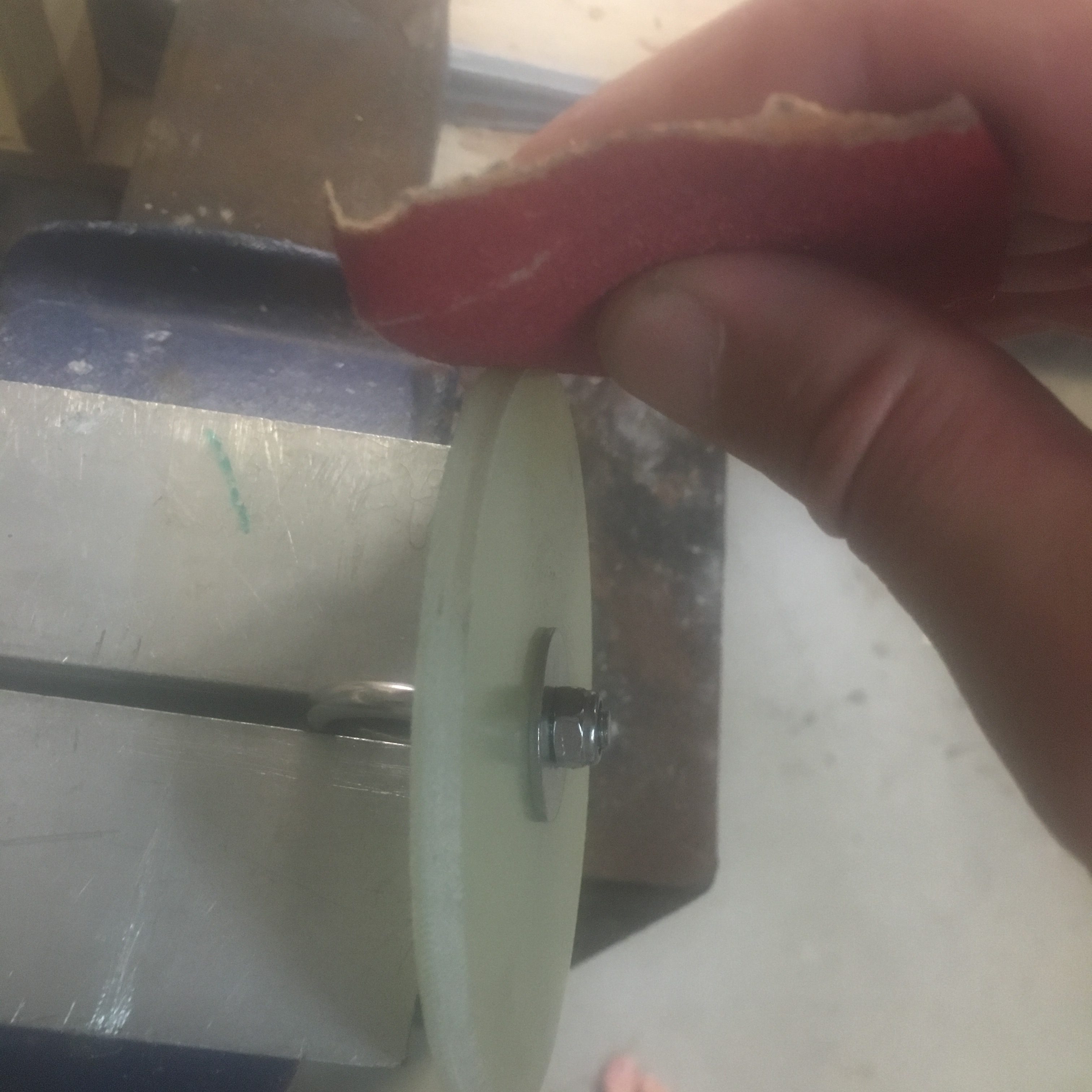
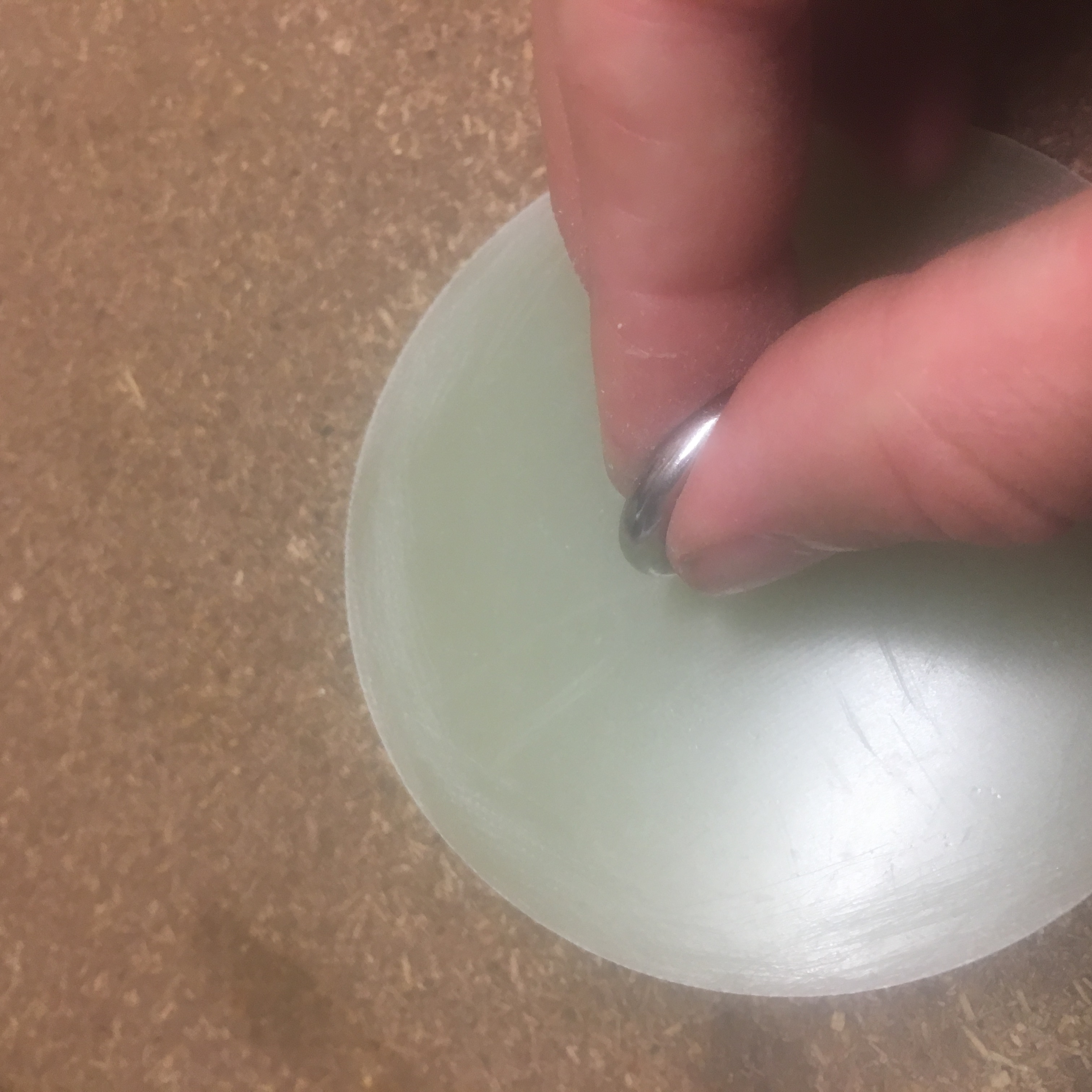
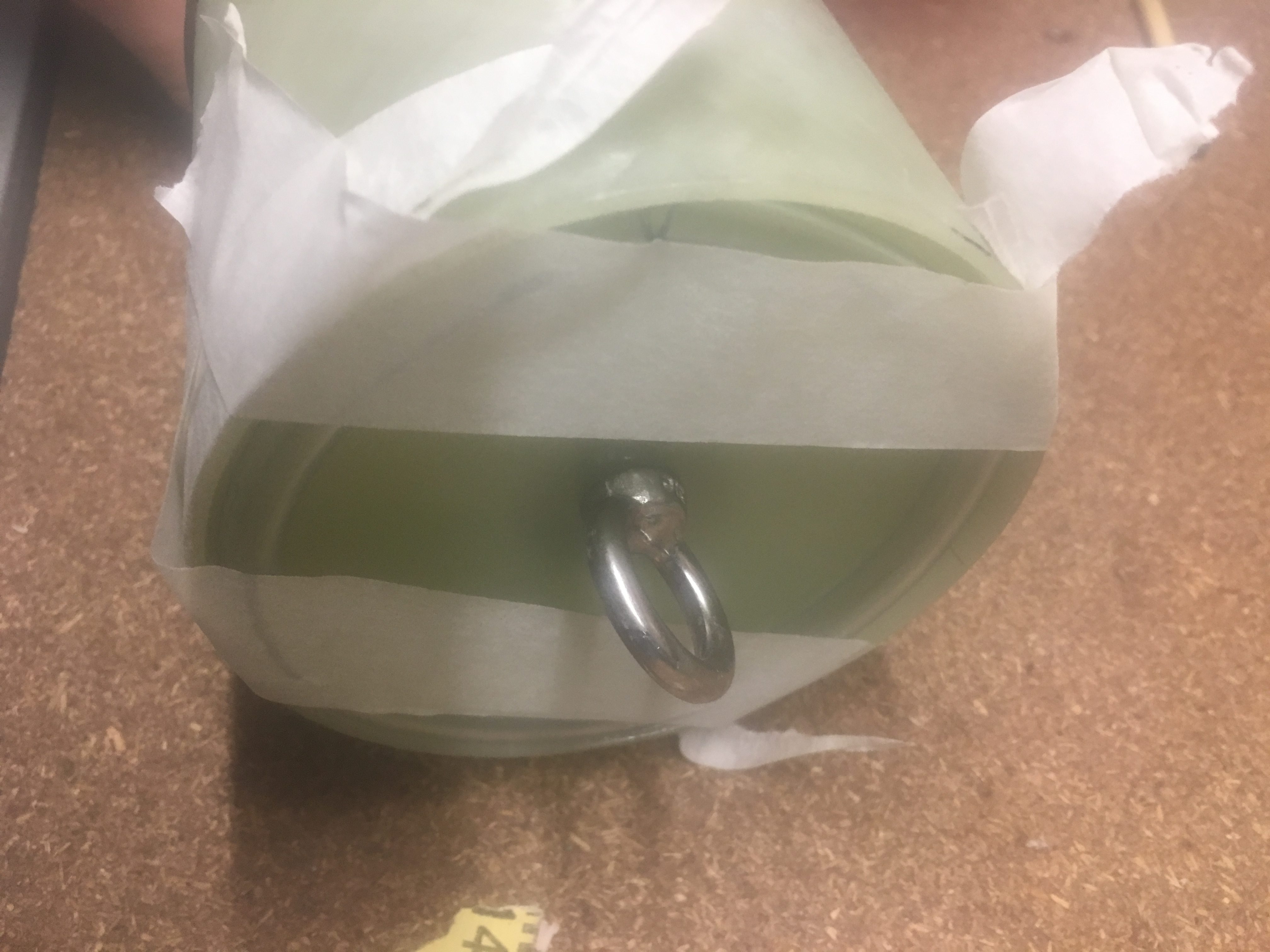
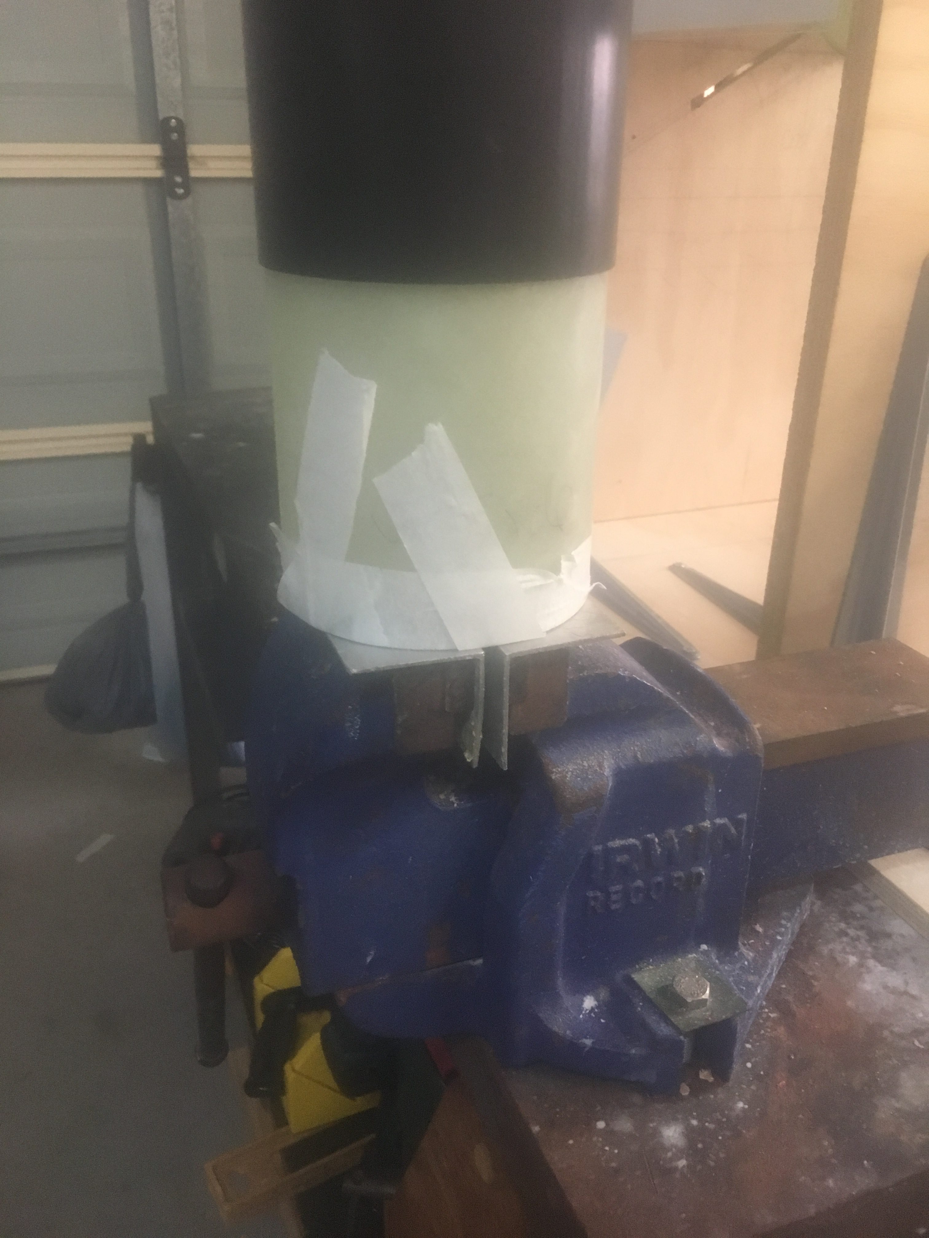
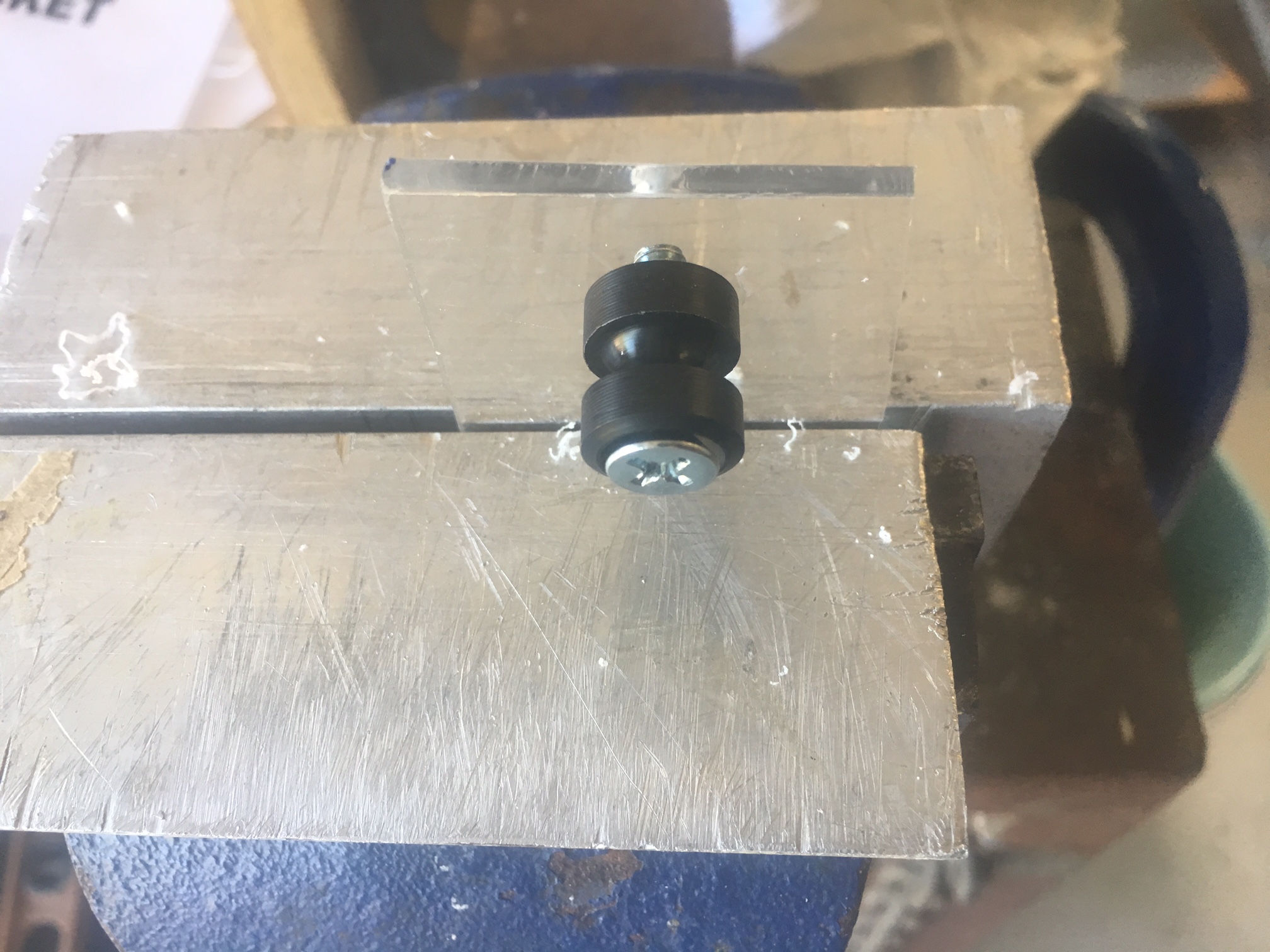
I did some very elementary tests on a single nylon screw using brick-layers thread and rectangle angle and luggage weigher. I did two tests
- Atleast 15kg at last look
- Atleast 11kg at last look
with the second test, it didn’t shear the screw, but instead pulled it through, so I consider this test to be some what unreliable.
The loading was also slowly applied and this might have led to change in properties. In summary, very hard to test. These tests just give us a very “basic” idea of testing. To test properly I would have to get some fiber-glass and install as they will be. Probably need to have three shear pins as well.
15kg translates to about 33pounds. This is close agreement to the theoretical calculated max shear stress of 14kg calculated below.
The Pressure Differential
We need to consider the TWO areas of the flight where the Ejection charge are going to be ignited. One at Apogee and one ~200metres above launch area.
We will assume that the flight is at altitude that is fairly close to Sea level, so that for all intensive purposes, Air pressure at found = 101325Pa.
We use the Air Pressure Calculator – https://www.mide.com/pages/air-pressure-at-altitude-calculator with :-
Pressure at Sea Level: 101325Pa
Temperature: 25 degrees C
Apogee – Drogue Chute (L2 altitude = 1200m)
For the most powerful motor, we expect an altitude of approximately 1200 metres. This means an air pressure of 88146 Pa.
i.e. Differential Air Pressure is 13,179 PA. This is 1.9PSI.
Apogee – Drogue Chute (max altitude)
For the most powerful motor, we expect an altitude of approximately 3500 metres. This means an air pressure of 71010 Pa.
i.e. Differential Air Pressure is 30315 Pa. This is 4.4 psi.
200m – Main parachute
At 200metres above, when the main parachute is deployed, the air pressure is 99024Pa.
i.e. Differential Air Pressure is 2301 Pa. This is 0.3 psi.
Diameter of Shear Pins
Preliminary investigations suggests the 2/56 shear pins will be the most suitable shear pins for this flight. So we only consider these.
AusRocketry has outer thread size being 2.184mm
Feretich web-site has:-
Major diameter: 0.0860″ (2.1844mm)
Pitch Diameter: 0.07440″ (1.890mm)
Minor: 0.06410 ” (1.630mm)
This agrees with what AusRocketry says. i.e. outer thread = Major Diameter.
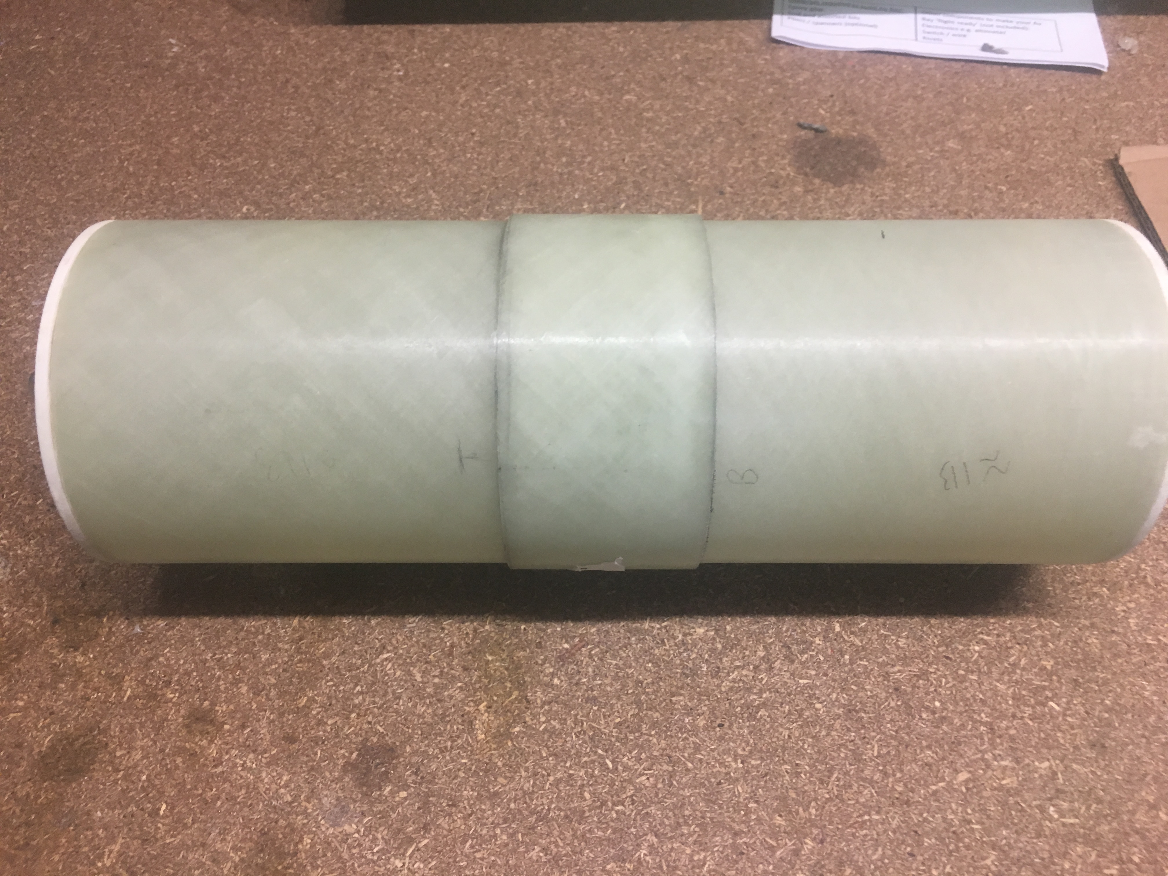
Rocket cavity
We need to consider both cavities separately.
Lower cavity – Drogue Parachute
Length: 740mm (29″)
Diameter: 99mm (3.9″)
Upper cavity – Main Parachute
Length: 400mm (16″)
Diameter: 99mm (3.9″)
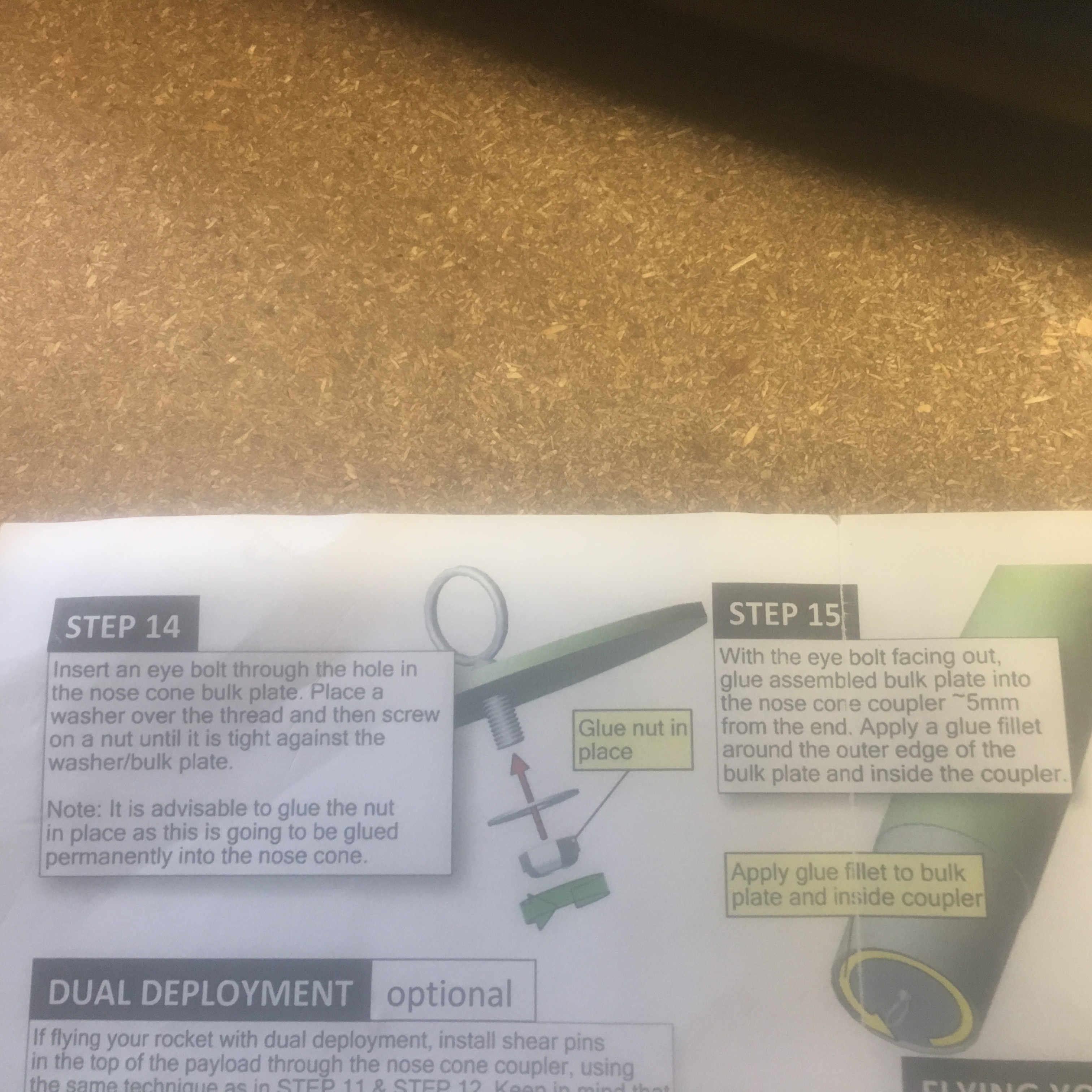
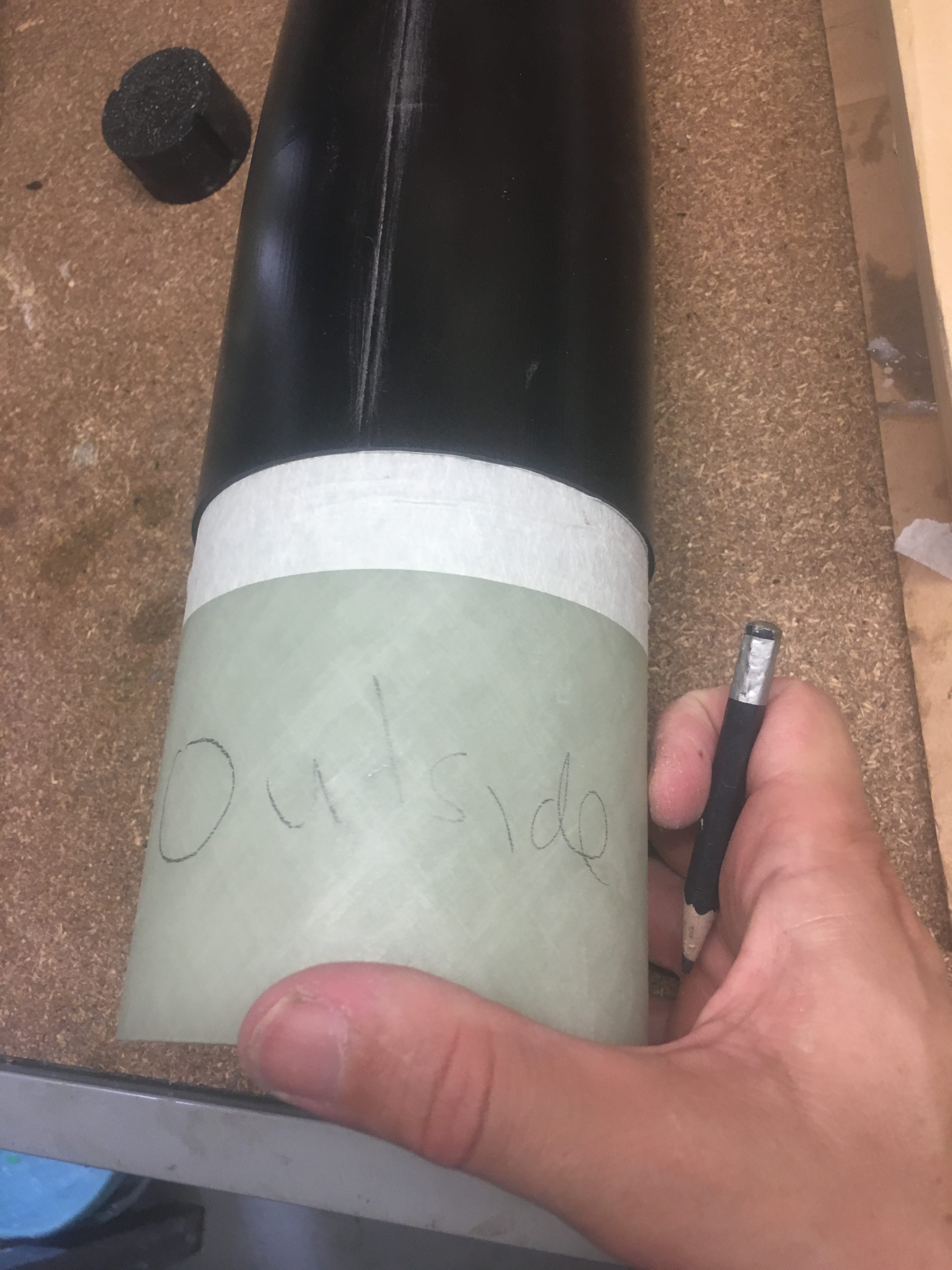
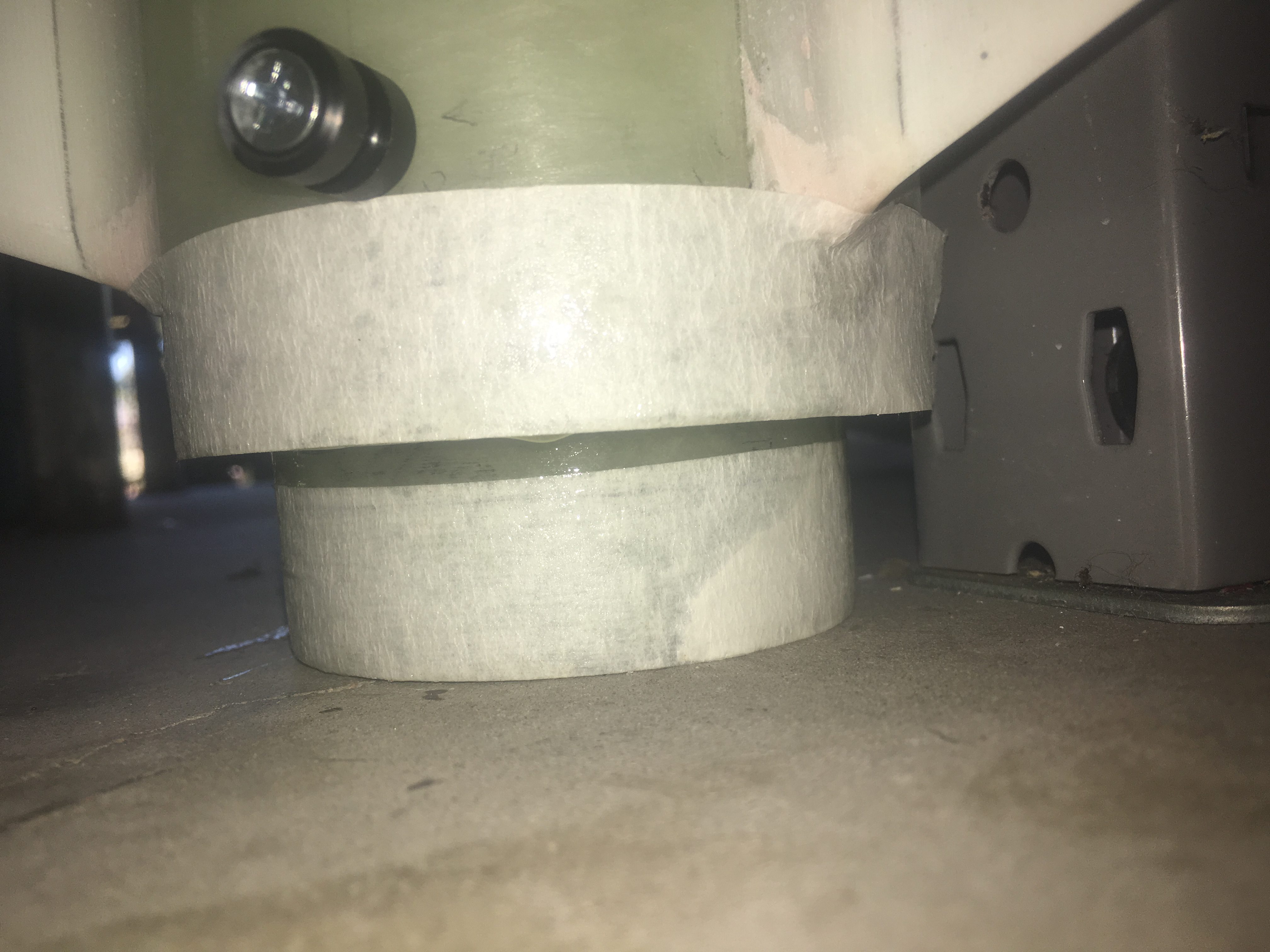
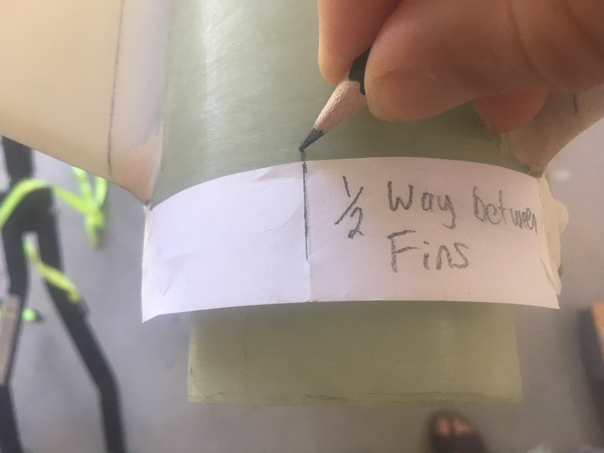
Where the Shear Pins need to be installed.
Two installs of shear pins need to be performed. One at the Nose cone between the Nose cone coupler and the payload Air-frame AND one between the Avionics bay and the Booster Air-frame.
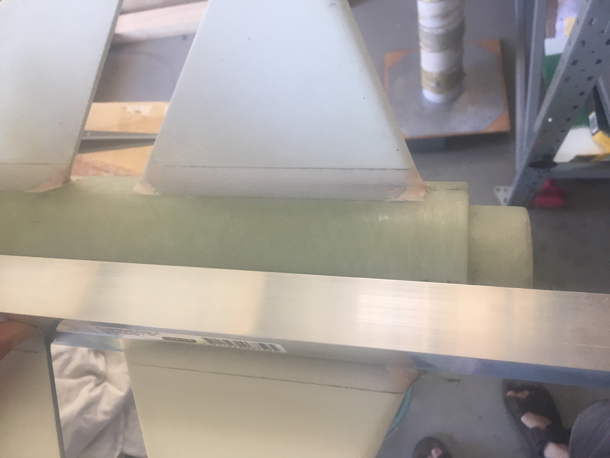
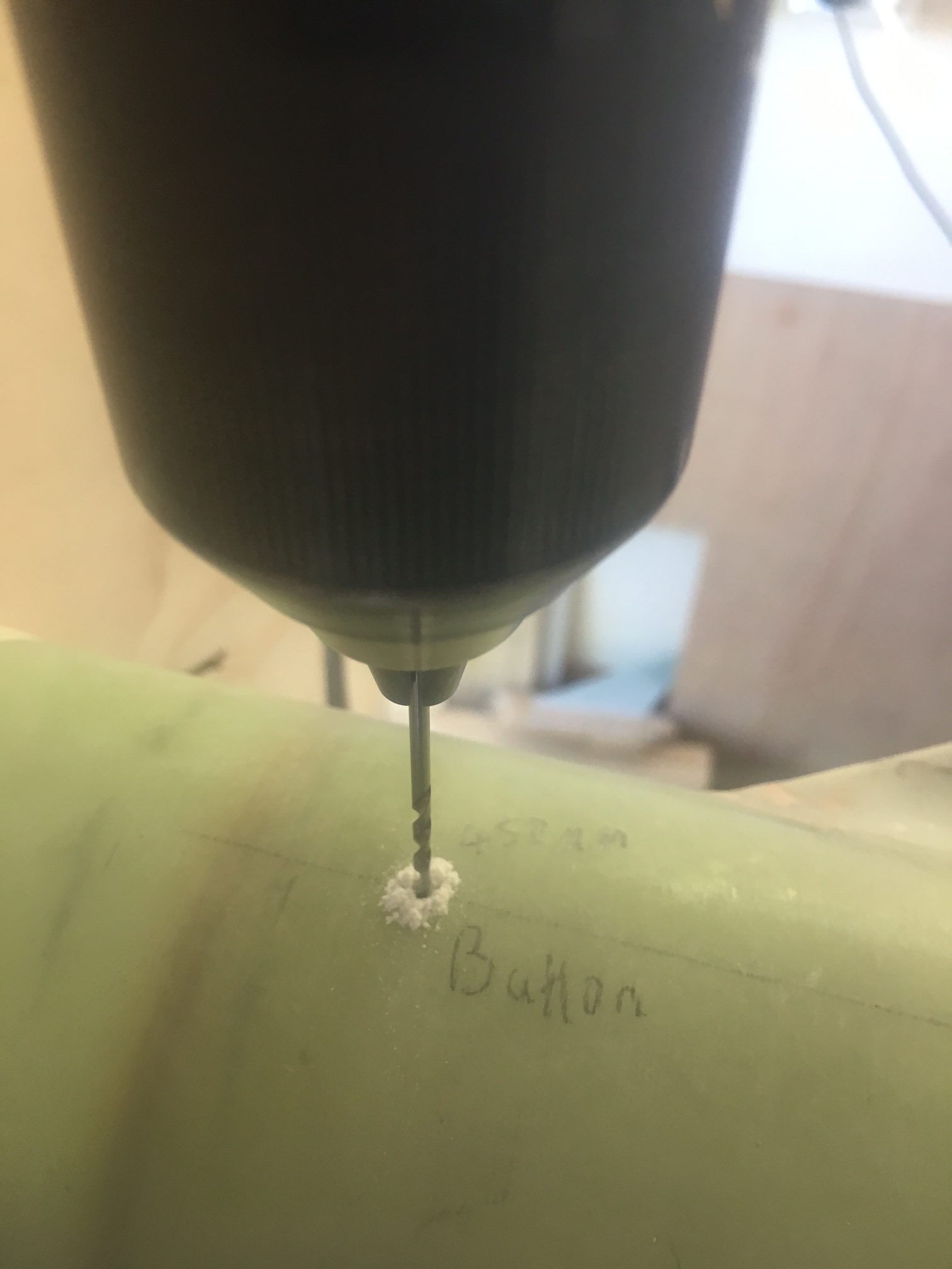
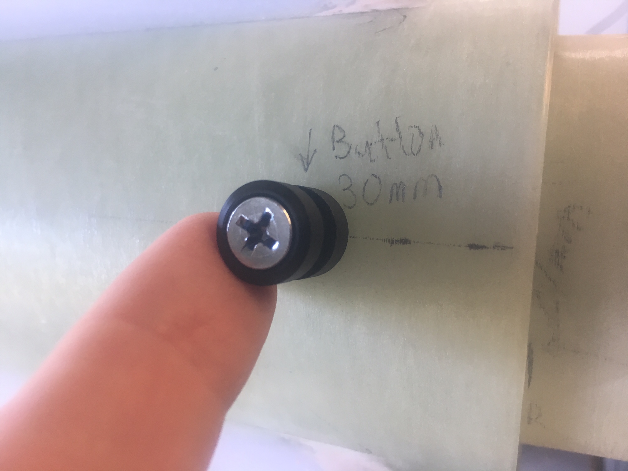
Each set is X # of pins (probably 3), 30mm set from edge of the air-frame ends , each hole equidistant from each other.
NOTE: It is possible that each set will have different number of shear pins. We will see.
Requirements of set-up
- Work on L2 flight
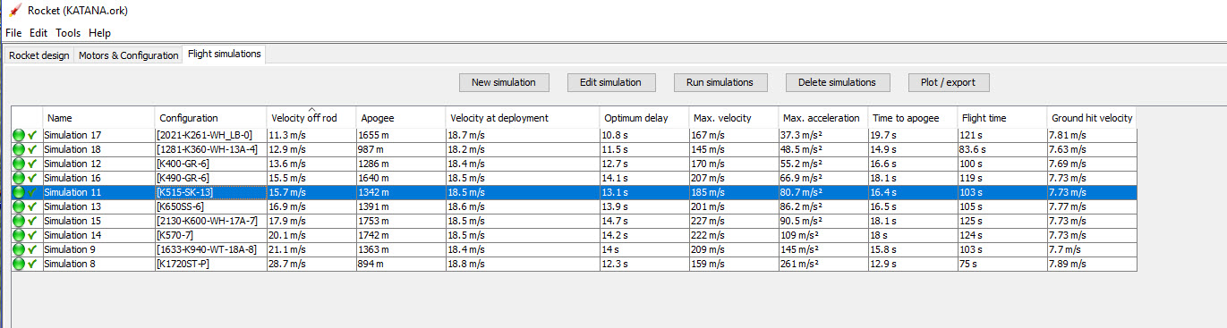
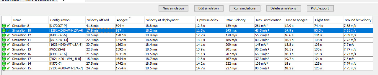
- Work with other flight profiles (> altitude than first L2 Flight profile). With L1395-BS (Total Impulse 4895), we have a flight altitude of ~3.3kms. So we decide that peak altitude we can safely fly the rocket is 3500metres
- Be able to stop premature separation
- Be more than capable of separation of components without blowing them up.
Calculating Shear pin Loadings
Both shear pin installs need resist the pressure differential at Apogee.
We assume that the cavity does empty/fill with air as it travels its flight. This is not strictly 100% valid, but should be close to it as we are depending upon this for our altimeter to give the controller the data it needs to know when Apogee is reached and later on when we are 200metres above the ground.
Let’s calculate the shear force that the pins can resist. Let’s consider the worst case scenario -lowest strength, minimum diameter
Minor Diameter: 0.06410 ” (1.630mm)
Minor Area: 2.09mm^2 (0.00323 square inches)
Shear Strength: 9600 psi
Force = Pressure * Area = 9600 * 0.00323 = 31 Pounds Force (lbf)
Now let’s calculate the force to perform the separation, focusing on the worst case scenario – highest strength, maximum diameter
Pitch Diameter: 0.07440″ (1.890mm)
Major Area: 2.81mm^2 (0.00436 square inches)
Shear Strength: 10500PSI
Force = Pressure * Area = 10500 * 0.00436 = 46 Pounds Force (lbf)
NOTE 1: 1 pound force = 4.45 Newtons and to convert 4.45 N to equivalent mass at sea level (to exert this force), we divide it by 9.81. 1 pound = 0.454 kg. So 31, 46 pounds force translates to 14 kg, 21 kg
Keeping the components together
The altitude for this flight is 1200m. At this altitude, the air pressure drops by 1.9PSI
Let’s assume that the air does not escape in time. This is obviously worst case scenario, but let’s do this. We need to consider both sections held by Shear Pins.
Area of cavity = pi * (d/2)^2 = 3.1415 * (99/2)^2 = 7697mm^2 = 11.9 square inches
L2 FLight
So the force due to the reduction of air pressure (worst case scenario) is:-
F = P x A
= 1.9 * 11.9 = 22.6 lbf
If we have three Shear Pins, then the maximum force they can resist (without any safety figure included) is 3 * 31 = 93 lbf
If we have a 25% safety margin, this brings allowable load to ~70 lbf
70 lbf > 22.6 I – So three shear pins is more than ample.lbf
3500 metre flight
Now lets consider the scenario with the more powerful motor.
F = P x A
= 4.4 * 11.9 = 52 lbf
70 lbf> 52 lbf- So three shear pins are is still more than ample.
Ejection
L2 Flight & 3500 meter flight
We want to know how much PSI we need to be sure that the ejection will succeed. i.e. we want the the PSI to exceed the rating of the shear pins. We also need to have sufficient force to ensure we overcome friction of fittings and any other losses
With three pins, the Force required to break three shear pins is 3 * 46 = 138 pounds Force.
Now, let’s round this to 150 pounds force. This should be sufficient to take into account any losses and additional forces keeping components together
P = F / A = 150/11.9 = 12.6 psi
NOW, if the air doesn’t equalise completely, then we will have even greater PSI differential = less chance of separation not occuring.
Things to note:
- The same PSI differential is required at both Drogue chute and Main parachute deployment. There is less likely to be a pressure differential at the Main Parachute deployment because there is more time for the air to equalise.
- There should be no real difference in charge required between the L2 and 3500m flight…yes there might be greater differential for the 3500m flight, but this will be working in our favour.
Selecting a suitable solution
So we select:-
- 3 * 2/52 Shear pins for Top (Main Parachute) configuration
- 3 * 2/52 Shear pins for Bottom (Drogue) configuration
Other thoughts
We can’t just leave it here. I have been bias against just two shear pins because of my concern that it might get stuck. Perhaps these concerns are unwarranted.
If we have sufficient quantity/size of vent holes, we can probably safely assume that there is significant equalisation which means the force pushing off the nose cone isn’t so great. This would mean we might only have 1/2 equalisation (guess)
F = P x A = (4.4/2) * 11.9 = 26 lbf
So with two shear pins supporting 2 x 31 = 62 lbf which with a 25% safety factor equates to 46.5lbf
So the force applied here due to air pressure differential is significantly less than the greatest force the pins can resist.
The bonus of this we can probably go for less Black Powder. If the maximum force they can resist is 62 lbf and we add 25% safety factor , this translates to 77lbf.
P = F / A = 77/11.9 = 6.5 psi.
Using:-
http://www.rimworld.com/nassarocketry/tools/chargecalc/index.html
For the large parachute, it is very well packed and will probably need a bit more force than the drogue to eject. So we got for 150lb of force.
We get :-
Tube Diameter (in): 3.9
Tube Length (in): 16
Desired Pressure (suggest 8 to 15 psi): 12
Grams of 4F Black Powder : 1.18 grams
and
We get :-
Tube Diameter (in): 3.9
Tube Length (in): 29
Desired Pressure (suggest 8 to 15 psi): 11
Grams of 4F Black Powder : 1.97grams … round to 2 grams.
This is still giving us a lot of extra margin – because we are producing 8psi of high pressure gas, rather than the 6.5psi, which is already 25% above what is needed to break the two shear pins.
I just need to convince myself on the wisdom of having two shear pins over three.
Eventually I decided to go for 3 shear pins.
Resources
Three very hand sites :-
- Discussion on Shear pin selection with calculations – http://www.feretich.com/Rocketry/Resources/shearPins.html
- BP Charge size Calculations – http://www.rimworld.com/nassarocketry/tools/chargecalc/index.html
- Air Pressure Calculator – https://www.mide.com/pages/air-pressure-at-altitude-calculator